Welcome to Our Community

Some features disabled for guests. Register Today.

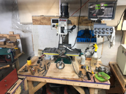
Grizzly G0758 Benchtop Mill Conversion

Discussion in 'CNC Mills/Routers' started by Rob Taylor, Oct 25, 2018.

  1. Shtf45acp

    Shtf45acp New
    Builder

    Joined:
    Mar 17, 2019
    Messages:
    5
    Likes Received:
    0
    The biggest problem I'm having is the gib lock levers. You can drastically move the tram. I also labeled the gibs while disassembling. It seems this is also a issue on the G0704 especially the bottom lock.

    Also maybe I'm being extremeex to picky. You say you have it trammed within a few tenths over a couple inches?

    With the gib locks at medium tightness, I have exactly .001" over a 6" machinist square. I have barely .0005" over a 1-2-3 block. Maybe my expectations are to high for this machine.
     
  2. Rob Taylor

    Rob Taylor Master
    Builder

    Joined:
    Dec 15, 2013
    Messages:
    1,470
    Likes Received:
    748
    Oh yeah no, that's plenty good enough for what this machine can do. Five tenths in three inches is great for a benchtop machine that hasn't been scraped in. Or most other machines, realistically, unless you're making really big parts.

    I don't have my gib lock levers installed though, they're not gonna be able to maintain a consistent tension over use so I don't see the point in bothering with them. The gib screws themselves seem to be pretty good at holding a position though.

    The frame's gonna flex at least a thou under load anyway, most of your parts are gonna be +/-0.001" at best unless you're really careful about your roughing and finishing cuts. You need one of the $2500 big-boy import machines and a surface grinder if you're gonna go tighter than that. Mass just can't be beat.
     
  3. riftware

    riftware New
    Builder

    Joined:
    Apr 9, 2020
    Messages:
    1
    Likes Received:
    0
    Greetings - like the other commentor I joined just to be able to follow along and see the pictures of your conversion. Congrats!
    I'm fairly new to metalworking - taught myself to tig weld last year and got the g0758 this year. (I mentor a High School Robotics team so we have a metal lathe at the school). I'm in the very early stages of following what you did - I just expect it to take longer. I've installed Y axis glass scales and I have an X scale arriving tomorrow. I've also got a Nema 34 that I intend to mount for the Z axis hopefully in the next week. Initially I'm going to just use it for power feeding the Z axis. I'll add power feeds to the other axis and then worry about converting to more accurate ball screws in prep for CNC. I think your post a couple posts back answered the initial question I was going to ask about dropping the head. While checking that my coupler I bought to connect the Nema to the Z axis fit, I managed to drop my head from 1/2 way up to the base. I didn't expect the head to be suspended by the lead screw - or rather I didn't expect that the lead screw wasn't attached all the way down at the base on a bearing. So when I removed the crank wheel and bumped the gibs lock the head sort of dropped down. No damage seems to have been done even to the endmill but that was an eye opener.

    So I guess my remaining question surrounds how you managed to adapt that nut at the top to connect with your Nema. I had hoped to be able to remove the motor and just throw the crank wheel back on if I needed to but depending how I do this I won't be able to. I need to make it so the nema isn't supporting the head just rotating the shaft....can you elaborate a little more on what you did? I'll go back and review the pictures again to try and figure out what I missed where.
     
  4. Rob Taylor

    Rob Taylor Master
    Builder

    Joined:
    Dec 15, 2013
    Messages:
    1,470
    Likes Received:
    748
    This is still a more-or-less ongoing project. Mostly on the smaller finishing details now, at least until I decide to rip out the spindle.

    Honestly I would keep it as power feed (probably X and Z, but Z is more important, it's a pain on this particular model) with glass scales (which are just really nice to use, though I haven't reinstalled mine after all- the motors and ballscrews operate at a similar level of accuracy, so I don't really need them. I can't recommend fully converting a mill this small to CNC at this point. The amount of time invested really isn't worth the payoff to me, vs a significantly larger unit and adding linear rails, but the machine itself is a fantastic little unit for a variety of projects when kept with basic manual mill upgrades. I'd like to do another more usable conversion at some point in the next few years using this machine to speed it along, though if I can jump straight from this to a Haas TM or MM, I'd be happier!

    Short answer: I didn't. I ripped out the leadscrew, installed the ballscrew on the custom plate, then added the motor mount with standoffs and used a standard spider-type coupler. Not great news for you, I know, but definitely one of the easier parts of the build so not the worst thing in the world. Also a 350-400mm ballscrew kit is dirt cheap these days, so it's worth just getting it over and done with. Just allow a method of disabling the stepper so you can lock the gibs for cutting and take some load off the driver.

    The nuts holding the cranks on don't really work very well for power feed interfaces (I used to drive them with an impact driver), you really need to mate directly with the shaft and key.
     
  5. Rob Taylor

    Rob Taylor Master
    Builder

    Joined:
    Dec 15, 2013
    Messages:
    1,470
    Likes Received:
    748
    Lest anyone be under the impression that this has fallen by the wayside due to my above slight negativity (which I stand by), it certainly has not! After about a year of occasional fiddling, fly-by-wire manual machining, dodgy Z-axis screws (that may or may not be related to certain ball nut unscrewing incidents), and general inability to meaningfully calibrate anything with devices that only measure over an inch or so, I finally started hitting this thing hard when I realized I was gonna need it to build M4, and could also do some decent laser upgrades (components are much cheaper now than they were in 2018!), whilst also getting it ready for primetime in its own right, machining actual production parts.

    I have a BT30 12,000rpm spindle cartridge and 4x6x8" block of 6061 aluminum to put on when I feel up to tackling that kind of project.

    Photo Sep 30, 16 21 06.jpg

    (The top one, the bottom one is a 24k 2.2kw ER20 spindle for M4- the air cylinder on the right goes with the BT30 spindle as well; sprung drawbar and petal clamp were included)

    In the meantime, sticking with the stock R8 spindle with TTS ER20 holders.

    Photo Sep 15, 14 01 13.jpg

    I've installed home switches, and reinstalled the glass scales, which made all the difference in the world when it comes to calibration. The axes are now mostly +/- 0.02mm or thereabouts, with some deviation in accordance with the C7 ball screw standard, which allows for +/-0.05mm over 300mm. It's mostly a case of getting a feel for the average and leveling the line where you feel it should go. I'm gonna do a video on glass scale calibration at some point, it's fantastic and applies to all machines.

    Photo Sep 15, 13 25 54.jpg

    The C7 spec isn't a problem when you have glass scales and a Mesa 7i85 serial/encoder card to plug them into, however. I've spent the last couple of days frantically Googling (because real information instead of roundabout discussion is shockingly scarce) and trying things in HAL (which is simultaneously the greatest and worst thing ever), and have LinuxCNC reading the scales and converting that value to a position. That process mostly looks like this:

    Photo Oct 21, 17 56 34.png

    Photo Oct 22, 13 05 00.jpg

    (And you thought grbl was complicated! o_O)

    I've successfully test-printed the values to the screen via G-Code subroutines!

    Photo Oct 22, 15 16 19.jpg

    (My x-axis homing pulloff currently goes the wrong way, so that includes what I'm guessing to be 0.05mm of uncompensated backlash?)

    Now all I have to do is build the files that will record multiple runs, backwards and forwards, of each axis, so I can look at them in a spreadsheet and do the appropriate regression (ie. "averaging") to produce the ball screw compensation files for each axis. These are 256-point files, linearly interpolated by LinuxCNC, of the requested position per your best attempt at calibration and the actual position both forwards and backwards (ie. a multi-position measure of backlash, too). That should bring me down to a 0.005-0.01mm accuracy, which is more than enough for me, I'm more interested in consistency at 0.01-0.02mm than arbitrarily chasing microns anyway.

    But this will allow me to make more pallets like this one, my very first non-test, fully CAM'd, multi-tool, multi-op CNC part (!!!):

    Photo Oct 08, 13 27 24.jpg

    And actually be able to reliably take them on and off the machine and probe them in without worrying about which areas are the least accurate or whatever.

    THEN I can get to work. :p

    Oh, and I'm about to install a jog pendant on the 7i76 too, which should, in theory, be a whole lot easier than finding information on glass scales and 7i85s. It's like 95% basic digital IO anyway.

    I have so much hype for this project right now it's ridiculous.
     
    Batcrave, Giarc and sharmstr like this.
  6. Batcrave

    Batcrave Journeyman
    Builder

    Joined:
    Apr 20, 2018
    Messages:
    361
    Likes Received:
    166
    Don't mind me, I'll just be over here in the corner, drooling.

    Opening the pod bay doors isn't the only thing it's difficult to convince HAL to do. It's immensely capable when you can actually get it to cooperate, though.

    I thought grbl was actually pretty easy to deal with... but HAL has brought me to the edge of tears on what really should've been fairly simple operations.

    Glad to see things are picking up, though.


    -Bats
    ("I'm sorry Rob, I'm afraid I can't do that...")
     
  7. Rob Taylor

    Rob Taylor Master
    Builder

    Joined:
    Dec 15, 2013
    Messages:
    1,470
    Likes Received:
    748
    I wish the machine itself could take anywhere near the power that it can put through (like 20HP/15kW for BT30 I think?), but I doubt I'd be using more than a 1kW motor- and even 500-600W would probably be ok. The BT30 is really just for the toolchanging- automated and not- and repeatability advantages combined with the significant speed upgrade from my ~2100rpm limit right now. An $1100 spindle cartridge (not including the air cylinder) is no joke though; if I convert another, larger machine like a Grizzly G0761 in future with plenty of Z-height for rails and probably a decent power boost up to 3-5HP, it'll be transferring over, there's no sense in leaving it on this one.

    I'm finally starting to somewhat wrap my mind around it, and it's both dead simple and incredibly complex simultaneously. Honestly I think most of the issue is the lack of really high quality, human-readable, well-organized documentation. It's a lot better than it used to be, but it's still not great. A lot of pointless forum-mining still.

    It's super simple once you're accustomed to machine operation and know some basic C to be able to roughly parse files, but if you're coming into it from almost a dead start, knowing basically nothing about CNC or control theory, as is probably the case for most people on here, I'm sure it appears pretty formidable.

    I'm hoping to avoid this one, but I have my suspicions... I built a usable x-axis screw map file yesterday afternoon, and it's not actually any more accurate than my previous manual calibration/compensation config when I run it, which has me very suspicious.

    Gonna adjust the soft limits and restructure the G-code file so I can do a multi-run with correct backlash direction this afternoon and do the averaging, hope that it settles down to usable figures, or else I might have to go the whole hog and figure out how to run closed-loop with the scales (something about leaving the P and D alone and only applying the scale to the I or something, from what I skimmed a while back). At least the manual config is usable for the time being, but I want meaningful heterogeneous repeatability.

    All I want is +/-0.01mm (0.00039") from nominal in both directions, I'm not asking that much! :ROFL:
     
  8. Batcrave

    Batcrave Journeyman
    Builder

    Joined:
    Apr 20, 2018
    Messages:
    361
    Likes Received:
    166
    And that is exactly what inspired most of the drool. I don't see an ATC happening any time soon on my ER16 spindle, and I'm not even sure what the point would be on the frankenmill.

    Oh, the problem is absolutely the documentation. I was constantly running into things that weren't explained clearly, weren't even covered, or were just plain wrong - some of it presumably due to later changes that the docs just never caught up with. It's the classic open source problem - you get something put together by a bunch of coders doing only what they're interested in, and none of them will ever want to write the docs.

    True - but from a dead start even Mach 3 can be a trial, and it hides all the cryptic config files. I suppose that's why we've got CONTROL.

    (have we ever gotten an answer on just what that's an acronym for?)

    My micrometer can read it - why can't my CNC do the same? :p


    -Bats
    (oops... my mic does .001mm. guess the CNC needs more fine tuning)z
     
    Peter Van Der Walt likes this.
  9. Rob Taylor

    Rob Taylor Master
    Builder

    Joined:
    Dec 15, 2013
    Messages:
    1,470
    Likes Received:
    748
    I do intend on at least exploring the options when it comes to an ER20 ATC on M4. I have some ideas that don't involve trying to stall the spindle at very low speed to tighten collets, but we'll see if they pan out. For the frankenmill, I'd just do what I'm doing right now; leave a 3/4" R8 collet in there and use cheap off-brand TTS holders. It makes a WORLD of difference even having meaningful manual toolchanging and consistent offsets for a tool table.

    Yeah, that sums it up. I'm gonna try and document what I learn, but since I'm using Mesa hardware and therefore running the HOSTMOT2 driver, it'll only really be applicable to other Mesa systems. Though at this point, and the relative ease I've had with every sub-project thanks to the Mesa hardware smoothing the way, I doubt I'd ever run any different, or recommend anyone else run any different, in future. For basically the price of a BlackBox you get some serious processing power and enormous extensibility. In the end, I added the scale with like, 5 lines of copied basic setup HAL code, one net I had to write, and an INI entry. The rest of it was taken care of by the driver.

    Yeah other than the lack of G53, which I think is critical to see, understand, and use- even from the very beginning- CONTROL seems like a great (and good-looking, which people overlook but helps) entry point with some pretty strong improvements this year.

    That's the point I'm trying to get to, at least within reason. I don't expect to hit tenths all day, but I do expect parts to come off and mate together with the level of fitment that I intend for them, even if I have to play with some wear comp at the control. I haven't quite determined what I'm gonna do about thermal compensation yet, but even if there's not much friction heat (I haven't generally run it for long enough to measure), the steppers definitely warm up and send that heat into the machine. If I have to water cool them, I guess that's a possibility. Maybe even use the same machine coolant that'll go in the sump, and have multiple loops- one for machine cooling, one for actual machining coolant, one for filtration, one for a radiator or whatever.
     
  10. Batcrave

    Batcrave Journeyman
    Builder

    Joined:
    Apr 20, 2018
    Messages:
    361
    Likes Received:
    166
    Interesting... Even for hand-cranked operation on well-aged leadscrews?

    It won't help those of us stuck on parallel, but on the whole that's probably not a bad thing - Mesa's the direction they generally seem to steer users anyhow.

    Yeah, yeah, I get the message... I gotta get me a Mesa board.

    I keep wanting to play with CNCing some water blocks, but, aside from finding time, I just haven't decided what to try cooling with them - although I suppose the Gecko could use some cooling. Maybe. I guess there's also the issue of finding/making fittings that won't corrode an aluminum waterblock and/or radiator. Or I suppose I could see how well the LEAD machines copper...

    You're thinking of using the same communal reservoir for cooling as for the reclaimed cutting fluid? Sounds messy - and if your filtration loop misses anything, you're going to have to worry about galvanic corrosion inside the radiator. And even that assumes your cutting coolant has the same properties you want for your cooling coolant (maybe it does - I don't know enough about mist/flood coolants).

    I think I'd be more comfortable with one PC-style loop - a small reservoir & pump, water blocks on the steppers & any other heat sources, and an appropriately sized radiator with fans (plus the spindle if you're going water-cooled) - to handle the cooling, and then treat the cutting coolant & sump entirely separate.


    -Bats
    (I think I'd be even more comfortable if I had the mill...)
     
  11. Rob Taylor

    Rob Taylor Master
    Builder

    Joined:
    Dec 15, 2013
    Messages:
    1,470
    Likes Received:
    748
    Yes- changing R8 collets and tools sucks. Get you some TTS holders, even if you don't use them for offsets, quick-change tooling is everything. It's like the difference between a lantern and a QCTP on a lathe. Also, glass scale DRO. DROs make live worth living when it comes to manual machines. The two biggest worthwhile upgrades by far, even including new lead screws, power feed, etc: DRO and quick-change tooling.

    It has marginally better documentation, at least.

    Even if all you get for now is a 6i25 and run the two parallel ports off of it, it'll make everything a lot nicer.

    Figuring out the all-alu or all-copper system is the first trick. Avoiding brass is the other one, at least for coolant, which can leech the zinc out over time in some cases, as I recall. Distilled water and antifreeze would probably be fine.

    Well, it's a recirculating system anyway, and they're usually dual-loop. Main lines to flood/misters, and secondary loop for solids filtration and/or oil skimming. I doubt the cutting fluid would be perfect for liquid cooling, but it would do something, which is all I'd really care about- some degree of stability, not absolute ability to cool.

    This is the way that Kern do it, with their aluminum/mineral epoxy frames, to hold microns all day. M4 is gonna have this type of loop on the spindle, so I'd have the parts available, and could easily cut some water blocks out of aluminum, since PC radiators are usually all-alu. Probably makes more sense, if slightly less elegant.

    Meanwhile, the mill just finished its 3-4 hour run, recording 20 +/- runs and ~10,000 screw datapoints, and now appears to be holding around 0.02mm (0.0008"?) or less most of the time (I saw it spike once to about 0.03?) with maybe 0.01mm or so of backlash. Which, in the grand scheme of things, is good enough, I think, just odd that it's still relatively far out. Just gotta do the Y and Z screws now too. Realistically it flexes up to 0.1mm/4 thou under higher cutting forces anyway, proper rough/finish passes are pretty much always needed, and very shallow 1-degree boring/helical toolpaths to stay happy. But non-aerospace-grade interchangeable parts should be pretty well achievable at where it's at now.
     
  12. Batcrave

    Batcrave Journeyman
    Builder

    Joined:
    Apr 20, 2018
    Messages:
    361
    Likes Received:
    166
    The DROs are definitely a must-have - at least at whatever point I manage to start using the damned thing with any regularity - but I'm still a little puzzled by the tool holders. I guess it didn't occur to me that putting a tool in the holder and the holder on the mill would be that much easier than sticking a collet & tool on the mill directly.

    Just mention your parport system to anyone on the forums & they'll start trying to convince you - directly or indirectly - that you really would be much happier with Mesa, that the Mesa tools are more capable & more frequently updated, and that whatever you're trying to do is going to be much better supported when using a Mesa card. It would feel almost culty, if not for the fact that they're right.

    Gotta watch out for what sort of solder they used on the radiators, too.

    Usually I just run with distilled water & a few drops of a dilute copper sulfate biocide, maybe a dash of detergent as a (less than ideal, but convenient) surfectant. I seem to remember there being some reason not to use antifreeze in PCs (or at least some reason it was less effective than plain ol' distilled water), but I can't remember what it might've been. It's been a while.

    Double-check before buying one. They used aluminum components in the very early days, but the PC market had gone over primarily to copper well before I built my first water cooled system (although I think EK put out a new series of aluminum components a few years ago... maybe because they could never pull their heads out of their assets to figure out how to do nickel plating that didn't flake off the day you brought it home).

    You've also gotta worry about the fittings, since those tend to be nickel-plated too.

    Bah. Good enough never is.

    Well, that's great for casual use & all, but how are you going to build me my space station?


    -Bats
    (space cadet without a space station)
     
  13. Rob Taylor

    Rob Taylor Master
    Builder

    Joined:
    Dec 15, 2013
    Messages:
    1,470
    Likes Received:
    748
    All you're doing is loosening and tightening- and you could have a Belleville stack and air cylinder do that part for you as well if you really wanted. As soon as you break the collet grip, the tool sides right out, no need to continue unscrewing the R8 collet all the way and screw another one in.

    Hmm, I'd still like to see some meaningful competition from a non-monopolistic proprietary vendor... That doesn't seem like a good basis to an ecosystem. It's the same thing as my iPhone... Just because Apple do it better, doesn't mean I don't want Google keeping them on their toes. That might be too nuanced an opinion for the internet, but there it is. Seems like it's doubly important on an open-source software project too.

    But... Mesa IS better if you're actually trying to like, get stuff done. :p

    I think it was this. Lower specific heat, I would assume. I doubt it's a big deal, I'm not trying to keep an overclocked RTX3080 at 20C.

    That's the trap I'm really fighting hard not to fall into. It's difficult when you can see the numbers even on the machine, though. I'm thinking for anything I do more than once, I'll be able to use wear comp offsets to adjust results to perfection, though. Should that actually be required, and my suspicion is that it's not, at least for most of what I'm doing. It should be able to hit +/- 1.5 thou all day without even trying, which other than mechanical fitments is a-ok 99% of the time.

    Today, in theory, I'm gonna knock out the Y and Z axis screw measurements, and get the parallel breakout I'm using for the MPG pendant (turns out, since they're like 18-20 wires depending on axes, parplugs are very handy for organizing and extending them!) mounted into the enclosure and hooked up to the 7i76. I clocked the quadrature signals out at the bench yesterday, so I know it's working. Fingers crossed I'll be able to get some spinny goodness happening by this evening! Likely tomorrow afternoon though.

    Oh, and when I get a chance, I'll post the screw-mapping G-code and some of the HAL/INI entries for these non-PncConf-wizard additions for future reference.
     
  14. Rob Taylor

    Rob Taylor Master
    Builder

    Joined:
    Dec 15, 2013
    Messages:
    1,470
    Likes Received:
    748
    Also, for the record, I've re-applied the gib lock screws, with locknuts, which should help maintain more consistent lash in the system. Some degree of chatter was definitely noticable with unclamped gibs, even when they were fairly tight on the taper. The actual flex in the system is of course still high, it doesn't really help accuracy so much as improve surface finish and tool life.

    Y screw data is collected, Z is running now, should be an hour or two.

    Here's the code for the X screw mapping:

    Code:
    %
    G94 G90 G21 G17
    G49
    G54
    
    (MUST BE RUN FROM A FRESH HOMING ROUTINE)
    G10 L2 P1 X0 Y0 Z0
    
    #<_loop> = 0
    
    F80
    
    (---GET INITIAL ENCODER VALUE---)
    M66 E00 L0
    #<_enc_start> = #5399
    
    (---FORWARD SUBROUTINE---)
    o100 sub
    (LOGAPPEND,xscrewmap_pos.txt)
    (LOG, POSITIVE)
    
    M66 E0 L0
    #1 = [#5399 - #<_enc_start>]
    (LOG,#<_X> : #1)
    
    o110 repeat [255]
    G1 X1.24
    M66 E0 L0
    #1 = [#5399 - #<_enc_start>]
    (LOG,#<_X> : #1)
    o110 endrepeat
    o100 endsub
    
    (---REVERSE SUBROUTINE---)
    o101 sub
    (LOGAPPEND, xscrewmap_neg.txt)
    (LOG, NEGATIVE)
    
    o111 repeat [255]
    M66 E0 L0
    #1 = [#5399 - #<_enc_start>]
    (LOG,#<_X> : #1)
    G1 X-1.24
    o111 endrepeat
    
    M66 E0 L0
    #1 = [#5399 - #<_enc_start>]
    (LOG,#<_X> : #1)
    
    G90
    G1 X-2 ; RESET THE BACKLASH, G54 OFFSET SHOULD BE ZERO
    G1 X0
    g91
    o101 endsub
    
    (---MAIN LOOP---)
    G91
    o200 repeat [20]
    #<_loop> = [#<_loop> + 1]
    (DEBUG, #<_loop>)
    o100 call
    (LOGCLOSE)
    o101 call
    (LOGCLOSE)
    o200 endrepeat
    G90
    
    M30
    %
    It's short and simple, really, though because it's almost entirely hand-written it took a few tries to nail the flow exactly how I wanted it, capture zero positions, etc. For some reason (LOG,#<_X> : [#5399 - #<_enc_start>]) would literally just produce a result like "1.24 : -0.425 - 1.698" instead of "1.24 : 1.273", so I had to move that calculation to a different line with an additional variable.

    The actual flow is basically "loop to one end whilst recording, close that file, open the other file, loop back to the first end whilst recording, close that file, reset the backlash direction, repeat X times". I added the DEBUG line that prints the current main loop number to the screen so I could keep an eye on its rate of progress, since it takes about an hour per 100mm of axis length.

    And yes, according to the LinuxCNC docs, the lower-case O's on the subroutine names is best practice to avoid confusing them with zeroes. I don't think they look similar, but I went with it anyway, can't hurt.

    Once you have all the information, you import it into LibreOffice Calc right at the control using the " : " as the cell delimiter, do some copying and pasting to make it convenient to work on (this is probably automatable but I don't care that much), and add an "average" column, I put it right in a new column B. A simple =(SUM(C2:V2))/20 formula to get the mean of the 20 results from the zero position, then just click and drag down to duplicate it to the other 255 rows.

    Copy the average column, Paste Special, unckeck "All" and "Formulas", check "Numbers", hit ok. I paste it all into a new file because the LinuxCNC COMP_FILE_TYPE = 0 makes it expect a "nominal forward reverse" format for every line so you include the backlash at the same time. Save that as a CSV with just a space as the delimiter, and then rename it to something like "xcomp.comp". Put that into HAL with the file type line under "COMP_FILE = xcomp.comp" or whatever, and you're done.

    It's super easy. This post over on the LinuxCNC forums helped enormously: How to map a ball screw?
     
    #44 Rob Taylor, Oct 24, 2020
    Last edited: Oct 24, 2020
  15. Batcrave

    Batcrave Journeyman
    Builder

    Joined:
    Apr 20, 2018
    Messages:
    361
    Likes Received:
    166
    Agreed. And it'd be especially nice to see an open source hardware vendor get into the game.

    (Hey, Peter! That's your cue!)

    But... yeah. Basically.


    Looks like it's treating [#5399 - #<_enc_start>] as string concatenation rather than an equation. Weird.

    Probably depends on your font... but, yeah, they do the same with subroutine file names too.


    -Bats
    (I know, I know... Peter hates Linux)
     
    Peter Van Der Walt likes this.
  16. Rob Taylor

    Rob Taylor Master
    Builder

    Joined:
    Dec 15, 2013
    Messages:
    1,470
    Likes Received:
    748
    Depends how much he wants to get into FPGAs and how much OpenBuilds want to hire a support specialist to give him the time to do so. :D

    FPGAs are amazing devices, but seem like a lot to wrap your head around.

    Yeah, super weird. Was the same with or without the magic "do this first" square brackets, so it appears that it's written to treat everything as a string except for known variable names. I didn't feel like fighting it, so I just moved the line.

    Z run is getting ready to finish up here, so I'm gonna get the two new screw comp files made and added to HAL, then get to work on installing the MPG pendant breakout! Making good time today.
     
  17. Peter Van Der Walt

    Peter Van Der Walt OpenBuilds Team
    Staff Member Moderator Builder Resident Builder

    Joined:
    Mar 1, 2017
    Messages:
    14,927
    Likes Received:
    4,291
    Probably 7-8 years ago, before I was with OpenBuilds i did play with the HostMot Stuff and got it to run on an cheap Xilinx fpga devboard over ethernet, not that hard. But the setup of this kind of stuff will never appeal to the consumer.

    edit: LinuxCNC/hostmot2-firmware
     
  18. Rob Taylor

    Rob Taylor Master
    Builder

    Joined:
    Dec 15, 2013
    Messages:
    1,470
    Likes Received:
    748
    Interesting. Maybe a 7i76e would be an easy build- the IO portion is just some buffers and encoder multiplexing, probably not that difficult for an existing hardware company.

    I still consider myself a consumer- machines are a means to an end, not the end in themselves! Besides, if the PncConf wizard could do the other stuff the cards can do, and stayed updated with the range and capacity, this would all be super easy and no one would really need to write HAL code. Literally anyone who runs grbl could install a PCI FPGA card, LinuxCNC, wire up a 7i76 (or other PncConf-supported card) to the stepper drivers and limit switches, connect them together, flash the bitfile, and get it working in 5 minutes with PncConf without knowing anything about Linux or HAL. An OpenBuilds FPGA card wizard could/would probably flash the bitfile to the PCI card as well.

    A BlackBox Advanced where the Brains board were a IO/encoder/spindle/etc board like the 7i76 but everything else was the same (maybe some extra plugs on the outside!) and an OpenBuilds version of PathPilot, which is just a skin over LinuxCNC now with everything pre-configured, would be amazing. It wouldn't be for the "how do I scale my spindle speed in grbl?" people, y'know, but it would be a great extension to the ecosystem. People wanting to add 4th axes to their LEADs and stuff.

    And since LinuxCNC is just a Debian distro with extensions, it could presumably be dual-booted on any Windows desktop without much issue.

    Anyway, I'm responding now because I wired in the MPG yesterday morning, only to find several hours of banging my head against it later the encoder itself doesn't properly output an A/B signal at the clicks, so I have a new one on the way for now. Couple more days, should be up and running.
     
  19. Rob Taylor

    Rob Taylor Master
    Builder

    Joined:
    Dec 15, 2013
    Messages:
    1,470
    Likes Received:
    748
    Update: original DID output proper signal, I'm just an idiot. Well, I haven't tested it again, but I'm pretty sure it was fine. Whatever, it can go on M4.

    Remedial lessons:

    1) Just because you're powering the MPG photodiodes from the 5V logic supply, does NOT MEAN that "inputs 16 and 17" on the 7i76 are TB3 logic pins 16 and 17. It means ACTUAL FIELD INPUTS 16 AND 17, ie. TB5 pins 1 and 2. (I'd read this repeatedly for days, but for some reason it had never sunk in) This is why logic GND and Field IO GND have to be tied together.

    2) MPG encoders are SUPPOSED to go through their entire A/B cycle inside of a single click. It's not A/B reverse voltages on each click.

    3) The HAL side of things are surprisingly easy. It's mostly just copying and pasting the example file- MPG Pendant -and tweaking pin names. Also, ilowpass is fantastic and should be used.

    The results are pretty spectacular: Login • Instagram :thumbsup: (You don't have to log in if you don't have an IG, that's just because the forum software can't log in to extract a page title. Also, sound on!)
     
    sharmstr likes this.
  20. JustinTime

    JustinTime Veteran
    Builder

    Joined:
    Dec 18, 2013
    Messages:
    780
    Likes Received:
    257
    Rob, don't you think that the X axis jogs 'reverse'? When you turn the control CW it goes to the left and vise versa. I would have thought it should go the the right when turning CW.
     
  21. Rob Taylor

    Rob Taylor Master
    Builder

    Joined:
    Dec 15, 2013
    Messages:
    1,470
    Likes Received:
    748
    Hahaha, it feels like it, yes! But it's because it's a traditional moving-table machine- the spindle's relation to the workpiece becomes more positive as the table moves further to the left. It's something you have to get used to with keyboard jogging as well- I assume it's the same for anyone with an OB MiniMill. CCW to lower Z is also slightly weird, but that's just the direction the numbers go! encoder.count is tied directly to axis.counts. I'll get used to it, I'm sure, because having it is incredibly nice! Part zeroing/probing with the keyboard jog is no fun, especially on z with a feeler gauge under the spindle.

    Today I figure out whether I want A) completely closed-loop operation via the glass scales. I get theoretically perfect positioning, but following error and axis stability may be variable. B) Open-loop operation with ball screw compensation mapping, which in theory is the best option, but I've found some spots where it's orders of magnitude out- like 0.3mm or so. Makes zero sense. Or B) give up on the idea of cheap C7 rolled screws ever being perfect, and just use a backlash compensation like I was before where most things were out less than 0.03mm and that's generally gonna be ok.

    I have all the required materials to go with any one at this point, since I was fiddling with closed-loop X last night just for fun, but I have no idea which is the best option.
     
  22. gml2059

    gml2059 New
    Builder

    Joined:
    Feb 8, 2018
    Messages:
    3
    Likes Received:
    0
    Great build!!! Apologies if I missed it but did you do anything to add more Z height (riser block, etc)?
     
  23. Rob Taylor

    Rob Taylor Master
    Builder

    Joined:
    Dec 15, 2013
    Messages:
    1,470
    Likes Received:
    748
    Nope, didn't change anything. I should gain a good 3-4" when I change out the spindle to the BT30 cartridge- the stock quill takes up a lot of vertical space that's completely unnecessary for CNC and the head is mounted quite low down on the column carriage. I'll probably add some light column reinforcement gussets or maybe a small tube frame when I change the spindle.

    Only having ~6" of Z height when using most TTS ER holders isn't the best, but that's why I'm pushing more palletization and am gonna either work on or buy a modular vise instead of the tall machine vises that are typically used. No real reason that the work should be more than an inch off the deck.

    But I'm not planning on significantly modifying the machine much more any time soon, I want it to produce parts before I start thinking again about what might need changing. I think I'll leave the spindle upgrade for another few months as well- 2100rpm is ok down to 1/16" tooling, it's just a bit slow. Once I'm confident in my ability to produce a precision bore, flange face and bolt pattern, and perpendicular side wall in a reasonable amount of time, I'll tackle that. I don't know that the (6x8") block of 6061 that I bought for the new head will actually fit in the (9") lathe, so it could get interesting.

    Anyone starting from scratch, I would strongly recommend just buying a base machine with sufficient (14"+) z-height to begin with, even if it's an extra $1000. Opens up a lot of meaningful options and time savings. Unfortunately, on the G0758, they didn't take into account the quill travel for the spindle-to-table distance so the spindle nose can actually touch the table with the quill locked for absolutely no discernible reason whatsoever. Should stop 2" off the deck and have a taller column, but alas.
     
    gml2059 likes this.
  24. gml2059

    gml2059 New
    Builder

    Joined:
    Feb 8, 2018
    Messages:
    3
    Likes Received:
    0
    Thanks for the response. Modular vice is a great idea.

    Such a shame about the Z height on that machine - I mean even the X2’s have considerably more. Otherwise the size of machine is perfect for my space constraints. The 704 table may be a bit big for me.

    Best of luck with running parts and future mods.
     
  25. Rob Taylor

    Rob Taylor Master
    Builder

    Joined:
    Dec 15, 2013
    Messages:
    1,470
    Likes Received:
    748
    I did fabricate a ~4-5" column extension, but it's about +/-0.010" in parallelism across the machined surfaces, which is obviously nowhere near good enough for something that's going to be amplified by the length of the column. Could have been welding distortion, though I did skip weld it and back-fill to minimize curvature as best I could.

    Photo Jun 13, 12 30 30.jpg

    It would bolt to the base through the 1" doubler, and then the column would sit right on top of the rib with the main plate drilled and tapped. This is the downside of the G0758 design, or any of the smaller machines, really; it's pretty easy to make a parallel block extension for a horizontal flange mount column, but these are rear-mounted vertical mounts... Not so easy, or as stable. Nor is it so feasible to just epoxy-level them. And an extension like this has to be parallel on the machined surface on the top to the other machined surface on the bottom of the other side. Not the easiest thing to set up in a small shop. Not impossible, though, if you were willing to try.

    If (and I might, living in a reasonably industrial area, but I've kinda given up on it at this point anyway) I had a decent machine shop with a surface grinder nearby, or just a grinding shop if I could re-machine it to less than 0.002" flat/parallel (and I suspect I could, with a long enough tool and a jack under the non-parallel'd side), this is a perfectly valid option given the fabrication capacity. I'm just not bothering at this point.

    I suspect I may just grab John Saunders' Mod Vise, just not sure which size yet. Trying to reduce the number of "shop" projects I'm doing!
     
  26. gml2059

    gml2059 New
    Builder

    Joined:
    Feb 8, 2018
    Messages:
    3
    Likes Received:
    0
    Agree - SMW modular vise the way to go and start making chips.

    The rear mount columns present some
    Interesting challenges for sure.
     
  27. Rob Taylor

    Rob Taylor Master
    Builder

    Joined:
    Dec 15, 2013
    Messages:
    1,470
    Likes Received:
    748
    So I did get the SMW stuff on Black Friday, finally arrived December 12th. Not a huge fan of the complete radio silence between order confirmation and ship notification (can't tell me when you issue the material PO/vendor ship/job queued/QC?), but oh well. Comes nicely packaged.

    Photo Dec 12, 11 38 43.jpg

    Finally got it onto the machine December 19th or 20th, and started the parts that I'd CAMed out the week prior.

    Photo Dec 20, 10 18 50.jpg

    This is the bar that became this clamp:

    Photo Dec 20, 15 21 27.jpg

    To hold the part while I contoured around the outside as a complete part, no tabs. Came out really nice, and sort of rounds out the last couple years worth of work:

    Photo Dec 22, 14 11 40.jpg

    Simple part, but a pretty big deal! Some adjustments made to the design in the intervening time too, of course. The original manual NN-14 was milled on the lathe(!) almost exactly 4 years ago, and is really what triggered the progress toward CNC and automation... Took three days to make the grip plates, and that black square is pretty rough:

    43.jpg

    The mill's the most productive it's ever been over the last week; made a second of a pair of laser upgrade parts, roughed out a lathe part, made this clamp (that serves for both front and rear plates on that thing), and made the plate itself (which could use some improvements, not least of which being not using a 4 flute when it should be a 3 flute- I think that's where the raggedy edges came from). Not sure it's ever made 4 parts in a week before (maybe during making the laser gantry carriage assembly?), and I'm only just getting started! Currently CAMing out the most complex part I've ever done (or will do, for quite some time).

    Of course there are a lot of parts to make for M4 as well, which is really what pushed me over the edge on the fixture plate- large plates are easier to fixture. The mod vice and fixture plate are a huge boon for regular parts though- would recommend for anyone running a smaller machine, like a 5050, especially if you make like, signs or engraved badges or anything repetitive. SMW do make large fixture plates for full-size routers, but they're extremely expensive. Can't say they're not worth it though.
     
    Vanagon_CNC, JustinTime and sharmstr like this.

Share This Page

  1. This site uses cookies to help personalise content, tailor your experience and to keep you logged in if you register.
    By continuing to use this site, you are consenting to our use of cookies.
    Dismiss Notice