Welcome to Our Community

Some features disabled for guests. Register Today.

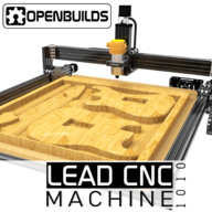
OpenBuilds LEAD CNC

Discussion in 'CNC Mills/Routers' started by MaryD, Nov 20, 2018.

  1. JustinTime

    JustinTime Veteran
    Builder

    Joined:
    Dec 18, 2013
    Messages:
    780
    Likes Received:
    257
    LOL, or two 123 blocks one on top of the other! :)
     
    Giarc likes this.
  2. Giarc

    Giarc OpenBuilds Team
    Staff Member Moderator Builder Resident Builder

    Joined:
    Jan 24, 2015
    Messages:
    3,008
    Likes Received:
    1,676
    I love my 1-2-3 blocks. Other than a digital caliper, they are one of my most useful tools. I love 'em so much I bought a second set!
     
  3. Ancientwollf

    Builder

    Joined:
    Jul 29, 2017
    Messages:
    6
    Likes Received:
    1
    I suppose it's good I stopped and noticed a disassembled anti-backlash block in my bag. The assembly video doesnt show anything about assembling it let alone setting it during the build and it looks like they are using an empty block- I know that cant be right and probably wont be happy if I assemble the rest only to find out I have to take everything apart to redo it. Any help with this? Pictures even?
     
  4. Ancientwollf

    Builder

    Joined:
    Jul 29, 2017
    Messages:
    6
    Likes Received:
    1
    Update- I did find this video. Need to note it in the videos guys...
     
  5. sharmstr

    sharmstr OpenBuilds Team
    Staff Member Moderator Builder Resident Builder

    Joined:
    Mar 23, 2018
    Messages:
    2,059
    Likes Received:
    1,448
    It shows the install of the anti-backlash nut at the 24:00 mark of the install video.

    nut.png
     
    Peter Van Der Walt likes this.
  6. Ancientwollf

    Builder

    Joined:
    Jul 29, 2017
    Messages:
    6
    Likes Received:
    1
    I was pointing out the tension screw and nut are not assembled or referenced in the video.
     
    eric bultman likes this.
  7. eric bultman

    Builder

    Joined:
    Jan 6, 2021
    Messages:
    15
    Likes Received:
    1
    I can 2nd the need to add to the assembly video. I now have to figure out how to add this screw back in!
     
  8. eric bultman

    Builder

    Joined:
    Jan 6, 2021
    Messages:
    15
    Likes Received:
    1
    I have not cut several items on my new 1010 have noticed the left side of my bed is lower than the right side. Front left is -.022" and the back is -.035", the front and back right side are level. What is the best way to raise the right side of my X axis, or lower the left? I don't really want to face off that much of my spoiler board because then I can't have a work piece stick past the cutting window. Thanks.
     
  9. Giarc

    Giarc OpenBuilds Team
    Staff Member Moderator Builder Resident Builder

    Joined:
    Jan 24, 2015
    Messages:
    3,008
    Likes Received:
    1,676
    What is it sitting on? Is the table level? It may be an issue with the table. This is where a torsion box table top helps. You can get a very flat work surface that flexes very little.
     
  10. eric bultman

    Builder

    Joined:
    Jan 6, 2021
    Messages:
    15
    Likes Received:
    1
    IMG_2931.JPG It is sitting on a 3/4" plywood board supported on all 4 sides. If the table wasn't flat I would expect apposing corners to be high which would indicate a twisted frame.
     
  11. JustinTime

    JustinTime Veteran
    Builder

    Joined:
    Dec 18, 2013
    Messages:
    780
    Likes Received:
    257
    Eric, plywood flexes and bows. Supporting it only on the outer edges, on a span of, let's say 4', is not enough. So do the aluminum extrusion, BTW.
    Having said that, .02" - .035" is so little that you most likely can't level, which is why the flattening of the sacrifice board is done.
    Do the surface flattening and than you can sand or hand plane the parts that are to high at the edges down so that you can put the material wherever you want and the cutting surface will be perfect.
     
    Giarc likes this.
  12. eric bultman

    Builder

    Joined:
    Jan 6, 2021
    Messages:
    15
    Likes Received:
    1
    Thanks, sanding down the parameter sounds much better in the long term vs. trying to add shims.
     
    Itchytweed likes this.
  13. Itchytweed

    Builder

    Joined:
    Feb 22, 2021
    Messages:
    22
    Likes Received:
    14
    Borrow a technique from the 3D printing side that I do on my 3D printer. Do a Z-axis touch off on the spoilboard in a grid. Pay attention to machine values unless you set work to a known zero. Locate your high spot and do a flycut on the spoil board to bring it down to the low level. This is a normal prep process and should only have to be done once. Plus, I avoid plywood because of its warping capabilities. I suggest resin impregnated MDF as it is more stable.
     
  14. Itchytweed

    Builder

    Joined:
    Feb 22, 2021
    Messages:
    22
    Likes Received:
    14
    Couple of suggestions for options/mods to the LEAD 1010:
    1) Offer the 500mm vertical 20x80 as an option rather than just the 250mm. This will allow for those who use a thicker board surface, especially if embedding t-track for hold down.
    2) From the design, it appears that the steppers are driven as X |YY|Z. Paralleled steppers can lose count and result in skew. I would suggest an option of adding another limit switch to be used on the Y-axis so the configuration now becomes X | Y1 | Y2 | Z. There are a couple of version of grbl out there that allow for dual steppers for X and Y axes. The added limit switch will allow for separate homing the Y carriage steppers and cancelling out any usage skew on homing.
     
  15. Peter Van Der Walt

    Peter Van Der Walt OpenBuilds Team
    Staff Member Moderator Builder Resident Builder

    Joined:
    Mar 1, 2017
    Messages:
    14,917
    Likes Received:
    4,290
    BlackBox has a slave driver, own driver for the Y2 motor: See docs:blackbox:jumper-slaveaxis [OpenBuilds Documentation] - not wiring motors in parallel

    Can be done: See docs:blackbox:jumper-slaveaxis [OpenBuilds Documentation] but in practice its much easier to just build the machine square instead - check every now and then that its still square, but unless you have a disaster, it kinda stays square anyway - leadscrews keep position well, belts can loose position easier when the motors are off
     
  16. Itchytweed

    Builder

    Joined:
    Feb 22, 2021
    Messages:
    22
    Likes Received:
    14
    I thank you for the reply.

    I beg to differ on leadscrew tracking. Closed loop control compensates but you have none on open loop and steppers can lose position when run this way. I'll stick to my use of independent shared axes homing as a personal preference.
     
  17. Peter Van Der Walt

    Peter Van Der Walt OpenBuilds Team
    Staff Member Moderator Builder Resident Builder

    Joined:
    Mar 1, 2017
    Messages:
    14,917
    Likes Received:
    4,290
    Of course, that's why we offer you the jumper options :) - to each his own :)
     
    Itchytweed likes this.
  18. Z295YQ

    Z295YQ New
    Builder

    Joined:
    Jan 27, 2021
    Messages:
    2
    Likes Received:
    2
    Hello, this is my very first post. I hope I post it in the right place. I bought Lead CNC 1010 and set it up and configure it everything was working fine. but for some reason it looks like Y and Y2 went out of sync and I can't get it to sync. when I bring up the system and hit home they are making load noise and Y2 seems stuck close to home or get to home faster than Y. any help appreciated. thanks
     
  19. Peter Van Der Walt

    Peter Van Der Walt OpenBuilds Team
    Staff Member Moderator Builder Resident Builder

    Joined:
    Mar 1, 2017
    Messages:
    14,917
    Likes Received:
    4,290
    Check wiring on the stuck motor: Only 3 of the 4 wires making good contact, or incorrectly ordered wires. See docs:blackbox:faq-identify-motor-coils [OpenBuilds Documentation]
    Check the cables as well using a Multimeter, could have a break inside, but usually boils down to a terminal that is loose / wire not inserted into the cage (but instead below the cage) before tightening
     
    sharmstr and Z295YQ like this.
  20. Z295YQ

    Z295YQ New
    Builder

    Joined:
    Jan 27, 2021
    Messages:
    2
    Likes Received:
    2
    that was it. one of the wires for Y went loose. Many thanks Peter.
     
    sharmstr and Peter Van Der Walt like this.
  21. MrKenSan

    MrKenSan New
    Builder

    Joined:
    Mar 9, 2021
    Messages:
    19
    Likes Received:
    1
    Hello Folks, considering a purchase of a 1010, a couple Q's hopefully someone can chime in on...

    1. We'll need to cut slots in aluminum plate. Have folks had success with this? (rigidity, repeatability? yes ofc feed rate matters, etc...)
    2. Is it possible to construct the frame/machine to a smaller than full sized footprint? We don't need that much build area for our application.
    3. "turnkeyness". By this I mean, all the controllers and machine playing well together. Ofc, it's a kit and needs to be built, but once built, what has been the general experience of folks in terms of getting things up and running, vs spending lots of time "tuning"?
    4. Any experience of folks exporting 3D CAD from SolidWorks, Inventor, or the like? Does the stock software provide a workflow to generating the GCODE from a STEP or STL?

    We're buying this to allow us to prototype some systems related to a COVID relief effort and want to be able to focus on our project, not the tools! :)

    Much thanks for your collective insights and Wisdom!
     
  22. MrKenSan

    MrKenSan New
    Builder

    Joined:
    Mar 9, 2021
    Messages:
    19
    Likes Received:
    1
    Hello Folks, one other question for the community...

    Is there a STEP or non-sketchup version of the CAD Assembly for the Lead 1010? We'd like to bring it into one of the CAD packages we use, but only see the assembly in SketchUp. Found the parts libraries and the collection of partial assemblies. Has anyone stitched those together into a complete machine?

    Much thanks!
     
  23. ICT Avatar

    Builder

    Joined:
    Apr 25, 2018
    Messages:
    6
    Likes Received:
    2
    Pen holder o65mm

    [​IMG]

    [​IMG]

    [​IMG]
     
  24. Peter Van Der Walt

    Peter Van Der Walt OpenBuilds Team
    Staff Member Moderator Builder Resident Builder

    Joined:
    Mar 1, 2017
    Messages:
    14,917
    Likes Received:
    4,290
    Looks good, you should consider posting it as a Resource in Resources | OpenBuilds with the files :)
     
  25. MrKenSan

    MrKenSan New
    Builder

    Joined:
    Mar 9, 2021
    Messages:
    19
    Likes Received:
    1
    Hello Folks, another question..

    Why does the Z-Axis have a different anti-backlash assy than the other two axes?
     
  26. Peter Van Der Walt

    Peter Van Der Walt OpenBuilds Team
    Staff Member Moderator Builder Resident Builder

    Joined:
    Mar 1, 2017
    Messages:
    14,917
    Likes Received:
    4,290
    Shorter, so one nut suffices. The dual nuts on other axis helps combat whipping
     
  27. MrKenSan

    MrKenSan New
    Builder

    Joined:
    Mar 9, 2021
    Messages:
    19
    Likes Received:
    1
    If one were to go with the larger height, then perhaps one approaches the same concerns? But OK... Just trying to find ways to keep things consistent. I'm rebuilding the entire machine in CAD, since there seems not to be one, and so visiting every component as I go.

    Also, FWIW, I found a bug in the CAD for the end-plates/motor mounts. The hole pattern for the motor mount does not precisely match the NEMA pattern, so the shaft is not concentric with the shaft hole on the block, hence the bearings are not concentric. I'm curious if this is a bug in the CAD you guys supplied (I started from the Solidworks version posted, that you guys commissioned) or if it's an actual bug in the design. I see an error of 0.7mm in one axis.

    Thanks for the response.
     
  28. Peter Van Der Walt

    Peter Van Der Walt OpenBuilds Team
    Staff Member Moderator Builder Resident Builder

    Joined:
    Mar 1, 2017
    Messages:
    14,917
    Likes Received:
    4,290
    Probably just the CAD, and the Solidworks library is older than the Sketchup library (the more official one)
     
  29. MrKenSan

    MrKenSan New
    Builder

    Joined:
    Mar 9, 2021
    Messages:
    19
    Likes Received:
    1
    Would be nice to have a solid model library like the Solidworks one. Sketchup is a walled garden, and really not the right kinda tool for this kind of machine design! Tho it's certainly one popular option, solid models (at least STEP) would be mighty handy.

    When I'm done here, I'll have a complete machine in Inventor which I could export to STEP if you would find it interesting/useful. Also intend to add some tweaks like improving the motor mounts, which seem rather "delicate" in the versions of the designs I've seen. A lot of effort is going into keeping the X-Gantry from flexing, but the motors are fastened by two long thin screws... seems like a prime candidate for twisting of the motor on start/stop.
     
  30. Peter Van Der Walt

    Peter Van Der Walt OpenBuilds Team
    Staff Member Moderator Builder Resident Builder

    Joined:
    Mar 1, 2017
    Messages:
    14,917
    Likes Received:
    4,290
    By the time the two M5s on big spacers are twisting, you have definately got bigger problems (;
    A lot of the design choices are mature over years of actual testing. But we also have 4-post plates: See C-Beam Motor Mount Plate as used in the LEAD1515
     

Share This Page

  1. This site uses cookies to help personalise content, tailor your experience and to keep you logged in if you register.
    By continuing to use this site, you are consenting to our use of cookies.
    Dismiss Notice