@Matthiu - I am thinking those are the blocks the will bolt to the plate as a stand off for the lead screw Anti Blacklash nut block. Block with 2 5mm holes and a slot in middle.[/QUOTE] That's what I was thinking after I posted. Thanks.
Not even close to finding them all. But, they are 1/8" BBs so I ordered a bag of them. I tried flushing them all out with solvent when I first got them because they did not slide real well. That improved them, but I think I will do what the video below suggests next to get rid of the sticky oil that was put on them prior to leaving the factory.
Extremely informative video. Thanks for sharing. I feel more confident about cleaning them. I was a little nervous been thinking I would mess something up and have to order more.
Nice! So I got my 250mm linear rails today. I was goofing around with them I have not cleaned them yet but I did notice a little stickiness till I placed weight on them. Once I place a small amount of weight with rails lying flat on the desk there was no more stickiness. They roll smooth with weight.Do you think they are designed to roll horizontally only? The other half of the linear bearings coming tomorrow! I decided to upgrade the Z axis first it was the weakest link to my machine.I have fresh Piece of aluminum for the the z axis also forgot about the t nuts so they are on the way too.
Hi Everybody, I recently bought the plates for this build as well, and I'm somewhat confused as to how to assemble the XZ plate with 2 antibacklash nut blocks on the Z axis. It seems that the screws for the X axis Nut Block interfere with the installation of one of the nut blocks for the Z axis. if anyone has any insight or preferably an image of how to correctly assemble the XZ plate, it would be greatly appreciated. Thanks!
I noticed mine roll better with weight on them too. With cleaning and the application of oil, some of mine would roll real smooth on their own, and some would take a little bit of force to get them going - not much. I categorized mine into three categories: super slippery, slippery, and meh - it'll do just fine. Super slippery will be my Y gantry since it has the most weight to move around. Slippery is the X, and Meh - it'll do just fine will be the Z. There was really only one of these. I am not concerned. It still moves smooth, just a little stiffer.
Sorry DewBerry didn't see your post. I did not buy these plates for myself. But looking at the Ebay picture of the z plate It looks like it has multi position for the Z axis and one for the X axis? I would say you can probably get away with putting only one anti backlash block on. I might be wrong but the short distance for the lead screw on the Z axis might not require 2 blocks. Just a thought.
Hi Mr. SORIN ILIESCU and good day. The system you built above, looks like a well designed system. I would like to buy the Sphinx and upgrade to the model that you show up above, the Sphinx 55 on MGN12 linear rails. Do you have instructions on your modification, or was there a video that you watched, showing you the procedure for the full modification? Thank you Mike
Amazing build. I would like to add ball screws with MGN15 rails and clearpath servos. Is there any way i can get your model of this either in sketchup or Fusion360 so i can modify it? I know a few people have been asking for it.
I recently purchased the plate set and linear rails to make this but am having a lot of trouble with getting the rails to slide smoothly while bolted to the plates. Does anyone have any suggestions for installing the linear rails?
The first thing I did with my linear rails was to completely wash out the original grease and then put good lithium grease. Also you should check the alignment of your rails. I used some 3D printed alignment blocks from there Search Thingiverse - Thingiverse, I think this one MGN12 Alignment Block by snicker
Okay so I printed out several of those blocks and they definitely helped with mounting the rails parallel to each other. It didn’t solve my issue completely though given that when I tighten the 16 screws that hold the gantry side plates to the 4 carriage blocks the entire assembly binds and won’t move unless a large amount of force is applied. Any suggestions with regard to that?
So i had a few problems with my Z axis plate not moving smoothly after converted it to linear rails. This was rough by hand not by stepper. I had to place and kept all the bolts loose then made sure plate was snug and flat against the blocks then snug 4 most outter bolts checked for smooth movement. snug'd down 4 more bolts checked for smooth movement when I got to a set of bolts that it didn't move smooth I back off those bolts one at a time checking for smoothness. Found the bolt or bolts that are binding leave them loose and tighten another set. Then go all the way around till all bolts are snug saving the the binding bolts for the last. Then after there moving smoothly when snug then tighten a tad more then snug to verifi. Technically it would be good to torque the bolts. That way you can be sure every bolt has right amount of tension on every block. Maybe even tighten in a criscross pattern. The thought is if you tighten one too tight it raised plate a tad caused a binding action. Or something is a little bent. Or maybe you need to clean blocks again. I had one block that I had to flush with propellant oil to get gunk out of bearing traces inside the block. Just a couple of road blocks I ran into.
Hi Chris, Hey I'm having trouble with binding . I found that the edges of the c beam are not true. is this something you've seen? and did you try to have the surface planed flat?
Linear rails, if preloaded, really need to be swept and shimmed parallel to within at least 0.0001" (0.0025mm) at every point along the full length. You won't be able to align them with a 3D print. Non-preloaded are probably ok in the 0.01-0.03mm range, and might be able to be aligned with a print, as long as you don't let the room change temperature while you do it. Of course aligning them to the C-Beam is irrelevant anyway- you have to align them to each other. That's what indicators are for. Co-planarity is less important but only if you measure any offset and rotation and shim your carriage plate mounts accordingly, otherwise the moment you apply to the carriages when you screw down the plate will also cause binding and wear. On top of that, any flex in the underlying structure (ie. the C-Beam) is also gonna cause binding, so that may also need reinforcing depending on what you're trying to cut and how fast. Linear rails are superior in every way... Except the number of tools required for installation.
Hello, First congratulation for your build. I have one question for you : Do you still use 8mm trapezoidal lead screw with plastic anti backlash nut or not ? If yes, can you tell me if this solution is robust enough according to you ? Thank you.
Yes, I use the 8mm trapezoidal lead screw and the plastic backlash nut, and for what this machine is supposed to do, it is a sound solution. Keep in mind that this is a router / engraver / milling cnc machine. If you want to use it as a milling machine, milling steel or cast iron, with 5mm depth of cuts at each pass, then of course you should look at a different machine to do that tasks. I cut hard wood guitar bodies on my machine and I push it to the max, never had an issue.
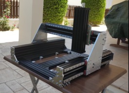
I'm new to the CNC scene, never owned one, but considering building something. I came across this forum and this thread, and I am impressed! I have some questions, in general about this design. there are 2 motors at the bottom to improve movement and reduce load. Is this not somewhat pointless as it cannot be done on the x axis? Would the motors not have turn with utmost precision to avoid binding on the rails? obviously being new to this hobby, I am questioning design choices wrt extrusion placement. I am sure it is done in a certain way on for some reason. My ideas: Would it be better to raise the bed height between the C channels? improved cutting clearance The C channels sit on extrusions, I assume this is stronger than if they were bolted on the side of the extrusions? anyway that's what I have for now. Would be nice to see how this build log is going, and I hope to learn more as I spend time on this forum!
Two motors are pretty standard. They do turn with precision and do not bind. The reason there is two on the Y is so it does not bind and also the Y axis has to move everything. The x axis motor does not have near as much mass to move around so one motor is all that is needed.
Thanks for sharing the build, I was wondering if the aluminium plates' dimensions can be found anywhere, I've been looking for them and all I had to do was model them on my own, which can be a bit painful. The issue is that I cannot buy them off of eBay it's somewhat complicated.