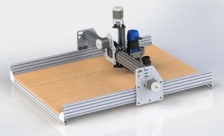
I see. I wondered about those urethane wheels. I think I read that they are quieter than the steel and are easier on the aluminum. What do you think? But you would think they would be more flexible maybe. Must be hard urethane or nylon I guess. I think one of the OX varients on here had more wheels added. I wonder if that was an attempt to decrease flex. At any rate, hope it goes smooth, quiet and rigid for you!
The Extreme wheels are hard enough to not have flexing, but they can move in the slot. Steel wheels would have been nice but, you cannot use steel on on aluminum. Hyteck2K design with the extra wheels will work well because the carriage is longer and he has added bracing of the two x carriage plates. I see more flex from the bolts and the nature of wheels running along a narrow slot. I just wanted to try something different. The biggest weakness of the OX design in my opinion is the GT3 belt system, but an ideal low cost solution to get everyone started.
What flex are we talking about anyways, I have been assuming that movement in the Y direction was causing flex\twist on the X beam. Not sure if I got my X and Y's right.
Y axis is the long axis which the gantry plates run along. When I mounted the router and push the top of the motor on the Z you can see far more movement on the router bit than I expected.
Not just plunge cuts, I'm concerned about flex in all the axis. IF the Z axis has flex then you don't have precession when the router is moving in the Y (long axis) under heavy cutting. I'm building this unit to machine carbon fiber plate, while this material is not hard I really want precession because I fit parts into cut holes. I may also consider cutting aluminium so just trying to make this machine strong.
Steve is right. The flex is most noticeable to the naked eye when doing drilling/plunging operations but make no mistake it's there when your just making passes and gets exponentially worse as DOC and feed speeds increase, when the gantry flexes that bad it effects the precision of your cuts so if your cutting a round hold it may end up more oblong then perfectly round, not desirable when trying to fit parts in those holes. Also any flex at the bit will result in you having to reduce your feeds and DOC due to chatter or inaccurate cuts. I use a .125 down cut end mill alot to cut a simple inner boarder on alot of my signs, I only go .05 deep and do 2 passes one climb one conventional, when the bit would plunge it would wander then come back inline as the router started moving, I ended up with "hooks" in my border (check out Florida Ox for photos). Steve's design is probably one of the most rigid i've seen here yet, i'm pretty stoked to see a working prototype or get in on the beta testing !! Gerald
Thanks Gerald, at the moment I'm learning from what has been done before and adding my own creativity. I can't wait for the linear bearings to arrive, but the first step is to replace the GT3 belts. I'm now playing with design concepts for lead screw & rack & pinion. I'm exploring if I can design new side plates which use EITHER drive approach for the Y axis. Plus adding a cross brace mounting point on the X to eliminate possible racking. First concept is the Y lead screws using the CNCRouter parts low profile mounting system and DumpsterCNC anti-backlash nuts. By using simple corner brackets and an extra Y extruded profile you create a strong bracket mounting system.
Is the original OX design too flexible in general? Or is it just too flexible for what you need it to do, but fine for the next guy? I'm still learning as much as I can before I commit to a direction. I'm all for maximizing capabilities from the start. As long as my financial backer is on board. I just got her a new laptop, so that may help me plead my case. I almost went the Shapoko route but read they were relatively flexible. Then I missed the most recent batch of ZEUS kits to ship. I'm glad i missed it now as I just figured out the controller is grbl only. I don't think I want to go that route. So now I'm back to figuring out all I can about OX and open builds.
I think the original design of the OX is good for light duty work. I have no regrets in the purchase but I think it's relatively easy to make a better version. Bolting the cross beams together is cheap and worth the effort, adding the inner plates is also easy and inexpensive, making better GT3 belts tensioner or doing double belts also simple. In my case I want a machine which does precise cuts, so I'm happy to upgrade the machine. This is still far cheaper than buying a heavy duty machine from a well known supplier. Plus it's lots of fun designing mods. I honestly think the OX is better than the Shapoko and everything else in this price range. The Zeus has the same areas of weakness as the OX. If I was to buy again, I would plan on doing the simple upgrades straight away... Talk with Gerald, he is working on selling parts for his strong version.
Thanks for all the info Steve. I like what both of you guys have done. Im a little disappointed to hear the belts are not the best. The more I deviate from the original OX the more time I will have to spend getting a working design. I am a little worried about not having a BOM to follow. Mainly from a time standpoint. Hi Gerald, I was looking at your build a last week or so. Very nice. I see you were planing on a BOM available. Do you still plan on doing that? Do you have a model? I can move this over to Geralds posts Steve if that is more proper around here.
No problem, in keeping here or moving to Gerald's. The belts are OK for light duty hobby work, I think the double version would be worth a try straight away... I decided to skip this step and jump straight to rack and pinion or lead screws.
Dave give me a few days and i'll have a BOM ready. I apologize for the delay, my sign business has kept me hopping for the last few weeks but i'm finally ahead of the game so i'll be working hard on having Area51 CNC Parts up and running. I am assembling the new gantry with the 5010 extrusion and updated plates this weekend. If everything goes together well cut plates should be available next week. Gerald
Unfortunately Dave, I think i'm the only one here with it... I went that way because my 5' x 9' machine has been running R&P for the last couple years with no problems. And so far the F-117 has been working flawlessly with R&P... I've probably cut close to 40 signs and some 6061 so far with it... Honestly though I think the costs associated with R&P or leadscrew about equal each other. Biggest difference in my book is you can build a 8 foot long machine with R&P but are limited to usually under 4 feet for leadscrew due to high speed whip. If your building a smaller machine 4x4 or under either would work great !!
I would love to see the BOM. Thanks. I'm hoping to follow in yours or Steve's path. I want to go large and stiff straight away. Then get fancy maybe in the future with vacuum tables , nice spindle, switches, cooling, chip shroud etc.
Is it easier to implement ball screws over r and p? I'm thinking any deviation in flatness would lead to play or backlash. Is the mitsumi extrusion straight enough? Just thinking that ball screws would not have this proven.
I don't have any issues with backlash or play, the springs tensioners keep the rack and spur gear in constant mesh with zero play, and I can guarantee my racks are not perfectly flat... Check out cncrouterparts, the pro rack drives are what I use on my big machine... Same thing, no play or backlash.. I won't be using Misumi extrusions any more, I'll probably still make the plates for people who want to order the Misumi extrusions themselves but after my last fiasco with getting hung up in customs I won't be using it in my kits, I figured it would be better use 8020 extrusion 5010. Easier to acquire..
I just checked out your videos again and found your spring loaded rnp drive. Pretty clever. Did you get the gear clicking noise to stop with more clamps. Are you worried about side loading the motor shafts? Same load as a belt drive I guess. How about gear separation forces? No problem I guess as you are making beautiful signs! Did you optimize the tensioning spring to make sure you only have just enough load to keep the teeth meshed.? Maybe I am over thinking this. Great looking machine. Love it. Oh yeah, I am in Canada and had no problems with mitsumi. Great experience all round actually.
The noise dissipated with 7 clamps on a 1500mm extrusion. As for side loading the shafts, ShopBot has used this system successfully for years on their PRS 5x8 machines without issue, so I don't think there will be a problem. The springs tension is a matter of trial and error, I go just tight enough to remove all the backlash then an addition 2 turns to preload the spring. I accidentally ran a toolpath today on that machine that was meant for the bigger one, a roughing toolpath with a .35 DOC @ 160 ipm with a .25 ball nose end mill. It went about 10 passes before I realized it was the wrong TP, never skipped a tooth, just kept on cutting. Only thing that kinda gave it away was the router bogged down a bit, made me look at the Mach 3 DRO. Anyway Thanks for the compliments and we should probably continue any further discussion on the R&P over on my build discussion. I don't want to clog up Steve's thread with all this...
I am in Ontario Steve. I ordered direct from Misumi in US. They love Canadians as I recall. I forget exactly, but there is some shipping/duty deal they have worked out with that is very reasonable. I ordered a few things there for a 3d printer frame I was attempting to make. They will cut then to length for a reasonable charge to. If I remember right, once you get down to a a certian length, the price got too high. So I got them to cut most of the order to size, and cut the short stuff on my table saw.
Hi Dave, I asked about your location because your welcome to my OX build. IF you happen to be relatively close... I understand Ontario is a big province! My home is Parry Sound, but also down in Toronto every week. Good news on the Misumi because I have had no luck finding a supplier in Canada
I live near Mississauga. Bit of a drive to Parry Sound. I wish you were closer. Thanks so much for the offer though! I am going to send you a private message if this forum supports that.
I had a 1/2" thick aluminium router mount bracket water jet cut last week. Today I did the drilling & tapping of the holes. A very solid mount, happy with this!
As many of you may have read I'm building a second machine with linear rails & ball screws, that left me with a problem, what should I do with my original machine because I was never happy with the belt drive. Option 1 was to sell it as it's stands today with belt drive or upgrade the machine to 5 start lead screws. I had already bought the CNC-RouterParts anti-backlash nuts. Gerald was kind enough to help me with the leadscrews from MacMaster which arrived yesterday. The 5 start leadscrews from mac-master are an amazing deal at $17.14 each and really good quality. http://www.mcmaster.com/#99030a704/=wd5alz So my design challenge was to develop a modification to re-uses as many parts as possible yet convert my standard OX to use leadscrews because I did not want to re-machine the new aluminium plates. I also wanted to make it easy for anyone with standard REV80 plates to make this modification using additional G10 or aluminium plates.
Plate set consists of front & rear cross brace for mounting stepper motors & Y axis leadscrew pillow bearings. Two 1/8" thick mounting brackets for the Y axis leadscrew and the CNCRouterParts nuts Four 1/8" or 1/4" thick mounting brackets for the X axis leadscrew & pillow bearings. Note I have re-used 4 of the original plate holes and the lead screw goes through the large existing hole with just slight modification. One 1/8" or 1/4" thick mounting bracket for the X carriage