Welcome to Our Community

Some features disabled for guests. Register Today.

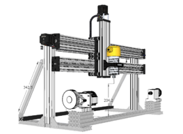
LEAD Lathe

Discussion in 'CNC Lathes' started by Giarc, Jun 14, 2020.

  1. Alex Chambers

    Alex Chambers Master
    Moderator Builder

    Joined:
    Nov 1, 2018
    Messages:
    2,783
    Likes Received:
    1,364
    I definitely want one now - better start putting the bits I need in a shopping basket!
    Alex.
     
    Giarc and sharmstr like this.
  2. Giarc

    Giarc OpenBuilds Team
    Staff Member Moderator Builder Resident Builder

    Joined:
    Jan 24, 2015
    Messages:
    3,015
    Likes Received:
    1,679
    A guy posted a lathe here awhile back and had written a post processor for vectric v carve. He has removed it since then, but I downloaded the post processor back then.

    I followed a vectric tutorial for using stl files and wrapping. It is actually really quick and easy to do. The software was well worth the money.
     
    Mark Carew likes this.
  3. wsims

    wsims New
    Builder

    Joined:
    Nov 12, 2020
    Messages:
    1
    Likes Received:
    0
    I'm working on a router CNC build in Technical college with a few of my classmates. First of all your build is pretty awesome! I I think if we could pull off a build even close to as good as yours our professor would be more than happy. This is not a kit build and since we only have another 7 working days to build it I kind of wish it was. We are frankensteining a build and only have an 8' by 4' aluminum table and some parts. You can see the table in one of the pictures.

    Looking at what we have, what would you say is a realistic time frame to be able to build this CNC? What steps would you take and in what order for this build? (roughly) There are 4 of us on the team. We are in an Industrial Maintenance & Mechatronics program. I'm a welder fabricator that went back to school. The other guys are inexperienced builders but have programming and electrical training. None of us have ever done anything like this before.

    Any feedback would be greatly appreciated!
    Thank you!
     

    Attached Files:

  4. Giarc

    Giarc OpenBuilds Team
    Staff Member Moderator Builder Resident Builder

    Joined:
    Jan 24, 2015
    Messages:
    3,015
    Likes Received:
    1,679
    I apologize for the late reply.

    I have to advise you, I am not an engineer nor a programmer. I am more of a reverse-engineer with and education from YouTube University and OpenBuilds University.

    As for recreating a lathe within the time period, that would be tough since I do not see a rotary axis in there unless I missed it. With what you have, I would make a simple xyz CNC build for a spindle, pen plotter or laser engraver.
     
  5. Giarc

    Giarc OpenBuilds Team
    Staff Member Moderator Builder Resident Builder

    Joined:
    Jan 24, 2015
    Messages:
    3,015
    Likes Received:
    1,679
    OOPS! Measure twice order once. :rolleyes: I was so excited to put this messy machine into an enclosure because dust collection is not as easy as the CNC router that I pulled the trigger and ordered the 510size. Everything would fit fine right... I forgot that to get the full cutting length out of the machine the head and tail stock will be outside the perimeter of the 510 enclosure. :banghead:
    DSC_0360.JPG
    I did not think about it until I unboxed all the components yesterday after work. By the way, it was packaged beautifully. But all my packages from OpenBuilds have been. Anyways, I believe I have a plan that will work because luckily I ordered a couple of extra lengths of 20x20 vslot.
     
    #35 Giarc, Nov 18, 2020
    Last edited: Dec 26, 2020
    Mark Carew likes this.
  6. Giarc

    Giarc OpenBuilds Team
    Staff Member Moderator Builder Resident Builder

    Joined:
    Jan 24, 2015
    Messages:
    3,015
    Likes Received:
    1,679
    Now to move to some larger stock! Hopefully now I will not have to worry about the collet hitting the parts on deeper cuts. This was more of an issue with the 1/8 inch endmill.

    DSC_0366.JPG
     
    Mark Carew likes this.
  7. Giarc

    Giarc OpenBuilds Team
    Staff Member Moderator Builder Resident Builder

    Joined:
    Jan 24, 2015
    Messages:
    3,015
    Likes Received:
    1,679
    It just dawned on me today, as I was trying to figure out how to carve out the hole for the drink can in a wooden stein like one of these (or deep wooden boxes)
    fanmug2.png

    that with just the addition of a Cbeam linear actuator and motor I can swap the plug from the rotary axis over and I have a Cbeam CNC with a very high Z! So, I just ordered one. This will also make it so I still have normal CNC capabilities when I break down my other one for the modifications I want to do.

    I also have a 200mm long, 8mm diameter endmill on the way so I can reach down deep enough since a 12 oz drink can is about 123mm in length. There sure is not a lot of selection in that length.
     
  8. Giarc

    Giarc OpenBuilds Team
    Staff Member Moderator Builder Resident Builder

    Joined:
    Jan 24, 2015
    Messages:
    3,015
    Likes Received:
    1,679
    I needed a place to store the old (circa 2011) Windows 7 laptop. All unnecessary software was removed. It only functions as the CNC controller. I was never able to get OpenBuilds Control to function on it so I reinstalled Estlcam. I drew up a quick computer tray that would mount onto and old TV swing arm mount. I have had this mount laying around for about 10+ years. It finally found a purpose.

    This mount was fastened to the side of the Enclosure wall with a large reinforcement "plate" made of HDPE on the inside of the enclosure wall. The tray was made form a "just barely large enough" plywood scrap. It was 3/4" thick so I did some cutouts to reduce weight and to add ventilation for the laptop.

    DSC_0544.JPG
    The hole for the locknut was cut so the nut would be a press fit...with a hammer.
    DSC_0546.JPG DSC_0550.JPG
    Perfect fit when stowed
    DSC_0552.JPG
    Painted black to match the cabinet and extrusions.
    DSC_0555.JPG

    And, since I am using Estlcam again, I added the Xbox controller for jogging. I printed a mount in my favorite filament color, Fire Engine Red. I also printed all the channel covers and wire clips in this filament.
    DSC_0558 (2).JPG DSC_0561.JPG
     
  9. Andrew Barley

    Builder

    Joined:
    Feb 23, 2022
    Messages:
    1
    Likes Received:
    0
    I have the same router mount as you with those lovely 6mm socket head screws out the back. Any possibility you could sell me another mount exactly like the one you have. I’m getting my house ready to sell so about half of my garage is packed up and hiding in storage. It would be attaching to that double long C beam width gantry plate with wheels on inside. It’s has 4 risers and another same gantry plate to use that open builds cover to prevent aluminum shards getting in the moving mechanics I am hoping to avoid. Anyway let me know if it’s not a problem or if anyway you can help. By the way your build is beautiful and ensured me I’m not crazy plus so many other good ideas I might be borrowing from you. Keep up the amazing work good sir!

     
  10. Giarc

    Giarc OpenBuilds Team
    Staff Member Moderator Builder Resident Builder

    Joined:
    Jan 24, 2015
    Messages:
    3,015
    Likes Received:
    1,679
    I am out of town for work right now, but I will message you when i get a chance to look at the file for the plate.
     
  11. BlackEdition

    Builder

    Joined:
    Oct 6, 2022
    Messages:
    4
    Likes Received:
    2
    How do you handle post processing from Vcarve? I'd love to build a similar machine, but can't wrap my head around how to appropriately prepare, process, and send the gcode. Sorry for the naive question!
     
  12. Giarc

    Giarc OpenBuilds Team
    Staff Member Moderator Builder Resident Builder

    Joined:
    Jan 24, 2015
    Messages:
    3,015
    Likes Received:
    1,679
    Here Is how I do everything. The post processor is linked below. I hope this helps you, and hopefully others as well.

    Disclaimer: IF YOU DO NOT WISH TO USE THE METRIC SYSTEM, NOTHING BELOW THIS STATEMENT WILL HELP YOU. Or you can edit/write your own postprocessor.

    If you have no issue with the metric system, then you will find, once you try this out a few times, how super easy it is to do this. For those that may find the metric system conversion difficult, Google is your friend. Also, Most 3D models on Thingiverse and elsewhere are metric.
    upload_2022-10-8_16-41-3.png


    So for rotary carving, I open a new job and select a piece of work stock that the 3D model will fit inside. I always zero on the "cylinder axis".
    upload_2022-10-8_15-56-6.png

    After clicking OK on the bottom left, I open the model import function and select "Import Component/3D model."


    upload_2022-10-8_15-57-51.png
    I choose from my files which one I want to carve and import it. I then make sure that it fits inside my work stock piece I chose for the carving. You also may have to adjust the orientation of the model to align the longest portion of the model down the center of rotation. Also, you can select "scale model to fit material."

    upload_2022-10-8_15-58-57.png

    Then I split the screen so I can see both 3D and 2D view. I open the 3D tabs from the "clipart" side tab. These are the tabs you use for holding the work while cutting it out so it doesn't come loose from the work stock. I use 3D pyramid tabs and you will see why.

    upload_2022-10-8_16-1-29.png

    I drag the 3D pyramid tab (Pyramid_0.5) tab over, and rotate it 90 degrees then stretch it out at least the height of the 2D drawing. I put one on both sides. You can see they now show up in "space" on each side of the 3D view
    .
    upload_2022-10-8_16-4-3.png

    Now I size them how I want so that it looks like a cone is going into the ends of the model. You want it thick enough they won't break. Now there is less to cut for the "waste" portions at the end and you have a strong tab.
    upload_2022-10-8_16-8-0.png

    Now open the toolpaths tab:

    upload_2022-10-8_16-11-44.png

    Choose 3D roughing:
    upload_2022-10-8_16-13-22.png

    Choose your endmill size from your database. Choose what you want cut. I usually choose material boundary to clear plenty of room for the collet if I am doing a larger model and my finishing endmill is not very long. I usually choose 3D raster but I change it to 90 degrees. Then I "Calculate" the tool path.
    upload_2022-10-8_16-21-35.png
    Below is the resulting screen for the 3D roughing. You can "Reset Preview" and then click "Preview Selected Toolpaths" and it will show it cutting the roughing tool path if you so desire.

    upload_2022-10-8_16-22-20.png

    I then choose the finishing tool path. As with roughing, I again select the tool (3mm ballnose), the part of the model I want cut, and the rastering angle. For finishing I go with either offset, or a 0 degree rastering. For ease of instructions I am showing it this way. Once you get more confident you can just select certain parts of the model to finish with different tools by drawing vectors around those areas.
    upload_2022-10-8_16-30-10.png

    Then click on "calculate" to generate that finishing tool path.

    upload_2022-10-8_16-30-45.png

    After you have your tool paths, select the post processor you want to use and "save tool paths." I use the Rotary Demon toolpath that can be found here: ROTARY DEMON CNC It is only in millimeters. So again, if you -- for some reason -- absolutely do not want to use the metric system, then you will have to write your own.
    upload_2022-10-8_16-57-25.png

    If you get more adventurous and do not want to finish cut unnecessary parts of the tabs, draw a vector (red dotted line made with the "Drawing" tools) around the area you want to cut and the choose the "Selected Vector(s)" for your "Machining Limit Boundary."

    upload_2022-10-8_17-8-13.png

    Then you can preview it and see that you did not waste time finishing much that is just getting cut off anyway. Notice only a small amount of the tab has been finished. I usually try to get this to a little over the endmill diameter of the finishing tool.

    upload_2022-10-8_17-12-44.png
     

    Attached Files:

    #42 Giarc, Oct 8, 2022
    Last edited: Oct 8, 2022
  13. A.J.W.E. Klappe

    A.J.W.E. Klappe Well-Known
    Builder

    Joined:
    Aug 13, 2017
    Messages:
    134
    Likes Received:
    88
    Hello Graig,
    Thank you very much for this detailed explanation. I just got my 4th axis in and this definitely helps in figuring out how to work with it. Bert
     
    Giarc likes this.
  14. Giarc

    Giarc OpenBuilds Team
    Staff Member Moderator Builder Resident Builder

    Joined:
    Jan 24, 2015
    Messages:
    3,015
    Likes Received:
    1,679
    Although not a rotary video, I found this one helpful.

     
  15. BlackEdition

    Builder

    Joined:
    Oct 6, 2022
    Messages:
    4
    Likes Received:
    2
    Thank you for your thorough, and very generous answer! Fantastic information.

    I am currently trying to design my own drum cnc like the one presented here: . A GRBL-based machine seems like the lowest barrier to entry, while a LinuxCNC-based machine provides the most future potential.

    I am a CNC novice, however, and am in the initial learning phase. As such, helpful answers like the one you provided are very much appreciated.
     
    LLPete and Giarc like this.
  16. BlackEdition

    Builder

    Joined:
    Oct 6, 2022
    Messages:
    4
    Likes Received:
    2
    @Giarc , apologies if you've answered this previously and my general naiveté. I understand GRBL's limitation of 3 axes. Is there a facility for defining one of those 3 axes as a rotational/angular as opposed to linear?

    In my background reading, I was under the impression that one needed to "trick" the system by wrapping a linear toolpath around an axis to achieve rotary carves with GRBL. However, in your (fantastic!) description of your vcarve workflow, you didn't seem to have to play any "tricks..."
     
  17. Giarc

    Giarc OpenBuilds Team
    Staff Member Moderator Builder Resident Builder

    Joined:
    Jan 24, 2015
    Messages:
    3,015
    Likes Received:
    1,679
    There are only 3 axis so I use the Y axis as my rotary axis. It made the most sense to me for this build since it rotates toward and away from me. The post processor I use basically uses coverst steps/mm to steps/degree. In this short video, I show how I calculated and calibrated it. Surprisingly, I did not have to change anything when calibrating. My values were spot on. My rotary has a 6:1 reduction. Most of the belted Chinese made rotaries come with the 6:1 reduction.


    Recently, I added a Y table to it which can easily be put on and taken off so I would have a back-up CNC router. It also has a lot more Z clearance for doing 3D caves. Y table for LEAD Lathe - essentially a High Z Cbeam XL
     
    BlackEdition likes this.
  18. NikCNC

    NikCNC New
    Builder

    Joined:
    Jan 24, 2022
    Messages:
    9
    Likes Received:
    1
    I know this was done a while ago, but I just added a 4th axes to my Open builds LEAD 1010. I am using vectric pro to make my toolpaths and ran a wrapping gadget using the open builds post processor, but it missed carving out much of the wood. I assume I need to configure a post processor that provides rotary angle information? Would you be so kind and provide some more detailed information on how to get this working properly? Thanks and sorry if this is a NOOB question, I have searched and only find stuff for the MACH machine.
     
  19. Giarc

    Giarc OpenBuilds Team
    Staff Member Moderator Builder Resident Builder

    Joined:
    Jan 24, 2015
    Messages:
    3,015
    Likes Received:
    1,679
    Yes I can help you out. I used the post processor at this link. It was made for a grbl based rotary built with openbuilds components. Rotary Demon Training
     
  20. Giarc

    Giarc OpenBuilds Team
    Staff Member Moderator Builder Resident Builder

    Joined:
    Jan 24, 2015
    Messages:
    3,015
    Likes Received:
    1,679
    I am out of town so not near my computer. I can give you other tips when I get back later this week.
     
    rksmith21 likes this.
  21. NikCNC

    NikCNC New
    Builder

    Joined:
    Jan 24, 2022
    Messages:
    9
    Likes Received:
    1
    Perfect, thanks so much!! Will look at this post processor.
     
  22. Giarc

    Giarc OpenBuilds Team
    Staff Member Moderator Builder Resident Builder

    Joined:
    Jan 24, 2015
    Messages:
    3,015
    Likes Received:
    1,679
    I should also mention that this post processor is for importing 3D models into your work stock piece. So, if you are designing your own decorative columns, you should save the model as an .stl file. If designing in Vectric, I would figure out how to make the wrapping toolpath work.
     
  23. rksmith21

    rksmith21 New
    Builder

    Joined:
    Feb 19, 2018
    Messages:
    12
    Likes Received:
    9
    This LEAD LATHE is cool. I'm starting to get the parts for building my own. Thanks for all the info. on it.
     
    Giarc likes this.
  24. NikCNC

    NikCNC New
    Builder

    Joined:
    Jan 24, 2022
    Messages:
    9
    Likes Received:
    1
    So far so good, the link you sent was awesome, and very thorough. I have all my tool paths created for my first project and hope to give it a go later this week.
     
    Giarc likes this.
  25. NikCNC

    NikCNC New
    Builder

    Joined:
    Jan 24, 2022
    Messages:
    9
    Likes Received:
    1
    So I finally had a chance to try out the lathe. I successfully cut down a 2.5"x2.5 inch block to a nice cylinder, but it appears the y axis is rotating 4-6 times faster than it should. So it will cut down the x-axis and then rotate around the y axis maybe 1/4 of the way around rather than running the next x-axis pass adjacent to the previous pass. I am using the same post processor you recommended and my y axis ratio is the same as your system. How do I modify the amount it rotates?
     
  26. Joseph Lewis

    Builder

    Joined:
    Oct 7, 2022
    Messages:
    1
    Likes Received:
    1
    I loved this idea of making a CNC Lathe and decided to do it over Christmas. I got it all working but the limit switches right now. I'm at the point of trying to write some G code for a basic table leg (I'm trying to follow the great instructions in one of the previous posts). Here is a picture of my machine. I only made one small change and that was to put a linear guide rail on the machine to adjust for different lengths of material. I also plan to mount a laser to it to be able to laser engrave the table legs as well (I'm repurposing a J-Tech Laser from a previous build). Here is a picture of my monster, hopefully I will have it running test pieces this weekend if I can figure out V-Carve. IMG_3182.jpg
     
    Giarc likes this.
  27. Giarc

    Giarc OpenBuilds Team
    Staff Member Moderator Builder Resident Builder

    Joined:
    Jan 24, 2015
    Messages:
    3,015
    Likes Received:
    1,679
    I show how I calibrate the Y in this video. I was surprised how accurate the rotary was. I did not have to make any changes rom the original "math". Try my Y steps/mm first, and if it is off a bit, then do what I did with a cylindrical object.

    The Y was 26.667 steps/mm rounded to 3 places. So, $101=26.667 in the grbl settings, or 26.6666666667 if you want to type that in.
     
    #57 Giarc, Dec 30, 2022
    Last edited: Dec 30, 2022
    Tim Cross likes this.
  28. Giarc

    Giarc OpenBuilds Team
    Staff Member Moderator Builder Resident Builder

    Joined:
    Jan 24, 2015
    Messages:
    3,015
    Likes Received:
    1,679
    I love the guide rail idea. I also bought a laser for mine, but I got distracted by a great little build originally made by David Bunch (Dedicated Compact Rotary Axis Laser Engraver) and used the laser for my rendition of that: Dedicated Rotary Laser Made from Scrap and Spares.
     
  29. NikCNC

    NikCNC New
    Builder

    Joined:
    Jan 24, 2022
    Messages:
    9
    Likes Received:
    1
    This is a complete noob question, but where do I type this stuff in? Do I modify the post processor? Do I need to connect to CNC via computer and not the interface? I feel silly, this is probably a super easy question
     
  30. NikCNC

    NikCNC New
    Builder

    Joined:
    Jan 24, 2022
    Messages:
    9
    Likes Received:
    1
    So I am an idiot, just plugged my computer into interface, backed up original settings and tweaked the y per your suggestion and everything is working great. So sorry, I have only used interface and forgot all about the computer interface to modify the grbl settings
     

Share This Page

  1. This site uses cookies to help personalise content, tailor your experience and to keep you logged in if you register.
    By continuing to use this site, you are consenting to our use of cookies.
    Dismiss Notice