Welcome to Our Community

Some features disabled for guests. Register Today.

H-Bot CoreXY Cube with Fixed Build Plate-

Discussion in '3D printers' started by TomH, Apr 3, 2015.

  1. TomH

    TomH Well-Known
    Builder

    Joined:
    Mar 10, 2015
    Messages:
    108
    Likes Received:
    12
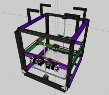
    Yes, my design uses largely uncut rails for multiple reasons: max build volume, build simplicity, and ability to build directly with available (all metal) parts (assuming they are reasonably precise lengths). I did decide to trim the three rails depicted in green by 4mm each for simplicity and to save $$$ in the build (by avoiding 12 spacers on the purple rails). Luckily there is a machine shop at my workplace and when my friend has some spare time I should get my rails back (probably +/- a few mils) so I'll probably end up with greater precision than I would have otherwise. :)

    I'll keep the harbor fright saw and diamond blade option in mind for the future....thanks (Adam and Kieth) for the tips!!! :thumbsup:

    I'm going to have to name this beast - it's going to have some serious mass! The OB components alone are 27lbs and when you add the steppers, build plate, etc. I'm sure this thing will weigh a good 40+ lbs (even without lexan enclosure or filament)....should provide substantial rigidity to counterbalance any forces resulting from the gantry movement (which will probably be about 1 lb. with rail/wheels/plates and hot end - actually just weighed everything and it is just shy of 16 ozs.).
     
  2. Keith Davis

    Keith Davis Veteran
    Builder

    Joined:
    Dec 11, 2013
    Messages:
    507
    Likes Received:
    398
    Tom - considering it's size, density, weight, rigidity and expand-ability to 4 extruders I'd go something like "Hercules", "Thor", "Zeus", "Bunyan". Outside of "bot" names everyone seems to try to emphasis how svelte their printer is. Well, you can't go there, but you can claim, "Size matters!".
     
  3. TomH

    TomH Well-Known
    Builder

    Joined:
    Mar 10, 2015
    Messages:
    108
    Likes Received:
    12
    I am also adding a Digital PID Temperature Controller with a relay and thermocouple to run the enclosure heater for filament drying. Since the dryer is integrated into the enclosure, it can also double as a chamber heater. With both chamber and plate heated I should be able to get some pretty good prints.
     
    #33 TomH, Apr 27, 2015
    Last edited: Apr 28, 2015
  4. TomH

    TomH Well-Known
    Builder

    Joined:
    Mar 10, 2015
    Messages:
    108
    Likes Received:
    12
    I had previously intended to have four head expansion to occur by using the opposing gantry plate. I now plan to mount both hot ends (e3D chimera and/or cyclops) on the same side, side-by-side. I only have Cyclops 3D models on hand but my first head is going to be a chimera and the second will probably be a cyclops. This arrangement will retain the most amount of printable area (probably 400mm x 390mm x 400mm with dual or tri/quad heads). I also plan on making a ducted fan optimized to not impact printable area...more to come...

    Capture.JPG
     
    #34 TomH, Apr 28, 2015
    Last edited: Apr 29, 2015
  5. TomH

    TomH Well-Known
    Builder

    Joined:
    Mar 10, 2015
    Messages:
    108
    Likes Received:
    12
    After giving Giuliano M. several tips on his build, I'm leaning on converting mine to a similar belt lift/spring counter balance arrangement. It increases the cost more than I would like but I really like the symmetry and open feeling of the build. It also provides Z-axis/gantry torque offset in all directions. ACME threaded rods act directly against the force with the largest mass in my current build and delrin wheels resist side-to-side forces. Belts at all four corners would be kind of hard to beat though, especially with approximate equalization of total mass with constant force springs like I suggested here (#95).

    Back to Sketchup for an alternate view...more to come...

    Oh, I picked up one of these at Walmart:
    http://www.3ders.org/articles/20141104-make-a-reusable-print-bed-for-your-3d-printer.html

    Figured I would try it out and see if it was a cheaper alternative to PEI - I haven't seen any references to testing with a heated bed so I figure I'll give it a whirl...
     
  6. adamcooks

    adamcooks Well-Known
    Builder

    Joined:
    Nov 6, 2014
    Messages:
    244
    Likes Received:
    65
    I can't wait to see how you work the new z stage.

    I backed the palette, can make 4 material through a single extruder.
     
  7. TomH

    TomH Well-Known
    Builder

    Joined:
    Mar 10, 2015
    Messages:
    108
    Likes Received:
    12

    Yeah, my son sent me the link for that. Pretty nifty feat of engineering - but too much complexity for my liking - may work fine but it seems like there are too many things that could go wrong and lots of calibration necessary. And $700+ USD plus shipping is over half the cost of my entire build. I can go from dual to quad for $130 with another e3d Chimera (though I think I'll do a Cyclops for $140) if I end up doing it.
     
  8. TomH

    TomH Well-Known
    Builder

    Joined:
    Mar 10, 2015
    Messages:
    108
    Likes Received:
    12
    Forgot to add the cost of two more steppers - about $36 (will print the extruders) - total cost to go from 2 to four extruders will still be under $200. My board (which I hope will arrive in June) was initially supposed to support 3 extruders but the creators are talking about adding another stepper driver to it instead of making an extension board - so I may end up getting support for four extruders out of the box!

    https://www.kickstarter.com/projects/1177488680/bbp-making-your-3d-printer-faster/description
     
  9. TomH

    TomH Well-Known
    Builder

    Joined:
    Mar 10, 2015
    Messages:
    108
    Likes Received:
    12
    Capture.JPG

    Here is a partial re-imagining of my build with four belts in lieu of leadscrews. I'm still not completely sold though.

    My leadscrew config is simpler, cheaper, and easier to maintain. However, I would appreciate other opinions on pros and cons of dual screw vs. quad belt (or tri/quad screw which I could also move to for the same or less cost since I already have two screws). I can't envision any Y issues from gantry mass movement with the leadscrews, and I am fairly confident that the wheels will adequately constrain any heaving or dipping from X axis movement - especially since, as in the case of the Y axis, movement is along the CG. And, with the weight of the Z axis, I don't expect backlash to be an issue. If I am overlooking any potential X, Y, or Z extrusion artifact issues that may be better addressed by a quad belt arrangement, I may still consider it - I'm just not ready to shell out $100+ and add considerable complexity (cost and complexity are some of my key design constraints) to my build unless I have a clear understanding of what it will buy me - I do like how it looks though.

    Thoughts?
     
    #39 TomH, Apr 30, 2015
    Last edited: Apr 30, 2015
  10. TomH

    TomH Well-Known
    Builder

    Joined:
    Mar 10, 2015
    Messages:
    108
    Likes Received:
    12
    To clarify for someone that asked me a question, my question wasn't about being less problematic to build/maintain - a dual leadscrew would be simpler/less potentially problematic in this regard than a quad belt. My question was primarily regarding any issues that may influence the build in X, Y, or Z directions and whether or not anyone could point to such issues that could potentially introduce artifacts in the build/layup with a dual leadscrew that would be overcome with a quad belt (and if these benefits were worth the cost/complexity of the different setup). My apologies if I wasn't being clear. If I was certain that a dual leadscrew was better, I wouldn't still be asking questions to anyone who may have knowledge/experience that may shed additional light on the subject.
     
  11. runninfarmer

    runninfarmer Well-Known
    Builder

    Joined:
    Feb 22, 2015
    Messages:
    99
    Likes Received:
    48
    I understand your question now, I apologize for not understanding before. I deleted my original comment, since it was rude, my bad. I've been inspired by your moving X, Y design and now considering making a similar version. I feel with a moving X/Y axis on a quad belt driven Z-axis, you could see some XY flexing in the Z axis belts. This is pure speculation though, so I have no equations backing that up.
     
  12. runninfarmer

    runninfarmer Well-Known
    Builder

    Joined:
    Feb 22, 2015
    Messages:
    99
    Likes Received:
    48
    You may want to consider over constraining the z-axis towers with wheels on the outside. I know that adds cost and makes it harder for a clean enclosure, but there's going to have to be zero play all along the Z axis. Constant directional changes and accelerations in X/Y may jar the wheels riding the inside rails.
     
  13. TomH

    TomH Well-Known
    Builder

    Joined:
    Mar 10, 2015
    Messages:
    108
    Likes Received:
    12
    After much further mental gymnastics I am definitely leaning on staying with the dual screw config. I plan on performing extensive testing to examine play, especially along the Y/Z axis differentials. It would be very simple to add additional wheels just under the side of the gantry frame and still stay within the enclosure. I may just go ahead and add them from the start - four L brackets and mini v wheels would do the trick and would only add $20 to the build.
     
  14. TomH

    TomH Well-Known
    Builder

    Joined:
    Mar 10, 2015
    Messages:
    108
    Likes Received:
    12
    I'm salivating for the delivery of my control board now - it looks like they have decided to deliver it with 7 on board 8825 stepper drivers (and more goodies)! So it will be very simple to upgrade my bot to quad extrusion!!!

    https://www.kickstarter.com/project...aster/comments?cursor=9771119#comment-9771118
     
  15. TomH

    TomH Well-Known
    Builder

    Joined:
    Mar 10, 2015
    Messages:
    108
    Likes Received:
    12
    How about the QuadBot Titan?
     
  16. TomH

    TomH Well-Known
    Builder

    Joined:
    Mar 10, 2015
    Messages:
    108
    Likes Received:
    12
    Ok, I'm back to my original plan with two leadscrews - I think it is worth proving out before over-engineering a solution to a problem that may not exist. I also raised the whole assembly 20mm by moving my angle and cube brackets up one segment on the bottom rails. With the internal rails under the bed, corner brackets, and the joining plates, alignment and rigidity shouldn't suffer. The extra space underneath on the corners also provides added space for my AC plug and switch, control board external switch, and space for a fan to provide plenty of airflow for the power supply and control board which will be mounted underneath. I also moved the extruder steppers to the inside so the bowden tubes are closer together and can be placed together along with the wiring to the hot ends. My plan is for all wiring to be underneath, within rails, within a drag chain, or plastic conduit for a clean look as well as wiring protection.

    screenshot_30.png

    I did play with some alternate setups though, here is a tri screw setup (minus ball screw nuts and mounts) with two steppers and one belt, easily modified to a quad as desired (with two belts). Either of these could also be changed to single stepper provided ball screws were used in lieu of lead screws.

    screenshot_29.png

    I found a supplier of (non-end machined) 500mm lead screws with ball screw nuts who would machine both ends to 8mm for a total cost of $72 for four:

    http://www.aliexpress.com/item/free...diameter-1204-Ballnut-CNC-DIY/1320913438.html

    So if any X/Y/Z artifacts arise that can't be addressed through wheel tensioning, I think this would be a more robust and cost expedient alternative to a quad belt setup.
     
    #46 TomH, May 2, 2015
    Last edited: May 2, 2015
  17. TomH

    TomH Well-Known
    Builder

    Joined:
    Mar 10, 2015
    Messages:
    108
    Likes Received:
    12
    Hopefully I will know in a month or two when I complete my build and fire it up! I have all the parts except for the control board for a dual lead screw setup. I may proceed with that for the initial build but I think I'm going to change it to a triple ball screw for the final build. I found an inexpensive source for ball screws and can drop to a single stepper for that config so the final build cost will be nearly equivalent and the ball screw config will be far superior (as well as providing more precision - at least in theory). Here is my current draft:

    Capture1.JPG

    The plan is to utilize ball screws and inexpensive pillow block mounts (with 3D printed supports for the bottom mounts) with the belt under the chassis. I may move to 32 tooth gears on the screws and a 16 tooth gear on the stepper (or 40/20) for added precision and less current draw/torque requirement on the steppers. The belt arrangement also allows for easy tension adjustment through movement of the two pulleys.

    Capture2.JPG

    There is still sufficient room in the center between the belts for the power supply (which has the largest Z height). The control board and other hidden components don't require as much Z space so there is plenty of room left over for everything else. FYI - there will be piece of lexan or hard board along with a 2mm piece of ceramic insulation between the heated build plate/build chamber and the chassis underneath where the electronics will be.
     
    #47 TomH, May 5, 2015
    Last edited: May 5, 2015
  18. adamcooks

    adamcooks Well-Known
    Builder

    Joined:
    Nov 6, 2014
    Messages:
    244
    Likes Received:
    65
    Those guys say they can make 6M ball screw. Thant may just seal the deal on a OX build for me. I want something that cut 4'x8' ply sheets and have a smoothie board lying around. An all screw OX would be quite nice
     
  19. TomH

    TomH Well-Known
    Builder

    Joined:
    Mar 10, 2015
    Messages:
    108
    Likes Received:
    12
    I'm also backing one of these...
    https://www.kickstarter.com/project...g-every-expectation-but-your-budg/description

    Looks quite similar to this...
    http://www.openbuilds.com/builds/indielc.1976/

    ...though less expensive (and mostly pre-assembled). It is also about 1/4 the weight of my build. I'm buying one for my robotics team so we will have additional 3D printing resources (and one that I will feel more comfortable loaning out to team members). I'm only getting an UNO version but it will be interesting to test side-by-side (I, of course, have to build mine first but since this one won't arrive until September I have a bit of margin). Though a semi-comparable model is about half the cost of my components I am looking forward to seeing how much difference a high-end extruder, heated chamber, PEI build surface, etc. will have on print quality.

    For $550 the specs aren't bad - Here is a comparison to mine:
    Table.JPG

    update: The item that is not viewable is Machinekit support...
     
    #49 TomH, May 6, 2015
    Last edited: May 6, 2015
  20. adamcooks

    adamcooks Well-Known
    Builder

    Joined:
    Nov 6, 2014
    Messages:
    244
    Likes Received:
    65
  21. TomH

    TomH Well-Known
    Builder

    Joined:
    Mar 10, 2015
    Messages:
    108
    Likes Received:
    12
    Justin, I am assuming that the Fastbot BBP1S (that I supported on Kickstarter and ships next month) performs as described and that the LCD cape they are making in conjunction is released soon (https://www.kickstarter.com/projects/1177488680/bbp-making-your-3d-printer-faster/updates). Otherwise, as the hardware appears to be nearly identical to the open source Replicape, I am fairly certain that it would work with a thing-printer Manga screen (http://www.thing-printer.com/product/manga-screen/) - it may just run out of the box but could potentially require Replicape firmware or some light modification of the BBP firmware. Though anything could happen, my bet is that the BBP folks do an LCD cape Kickstart soon or just start selling boards and LCD capes, etc. Worst case, since the Manga screen isn't currently available I will have to build one myself (https://bitbucket.org/intelligentagent/manga-screen) and determine if it just works OOB or requires some slight BBP firmware mods (which I should be able to decipher by comparing BBP firmware to Replicape firmware). There may also be other options, though I will only investigate further if the BBP LCD cape doesn't come to fruition.
     
  22. TomH

    TomH Well-Known
    Builder

    Joined:
    Mar 10, 2015
    Messages:
    108
    Likes Received:
    12
  23. TomH

    TomH Well-Known
    Builder

    Joined:
    Mar 10, 2015
    Messages:
    108
    Likes Received:
    12
    Found this 24 x 48" piece of .375" ultem on eBay for a song! I plan on carving out a 400mm x 400mm piece and selling the rest. I may actually make money! I also have a piece of garolyte for nylon and a piece of glass for glossy flat PLA printing. I plan on clipping either surface on my 6mm aluminum heated plate as needed for the desired filament type.

    FullSizeRender.jpg
     
  24. TomH

    TomH Well-Known
    Builder

    Joined:
    Mar 10, 2015
    Messages:
    108
    Likes Received:
    12

    Openbuilds made good on the poorly cut rails with an in-store credit. So I am getting another lead screw and some other stuff for my robotics team. I decided to do belt driven lead screws at a 2:1 gear ratio to ensure sufficient torque is available for a single stepper to drive all the screws. I may still try two screws first just for grins but I may end up doing 3 anyway for added stability in case I decide to strap a dremel onto my gantry to play around with.
     
  25. TomH

    TomH Well-Known
    Builder

    Joined:
    Mar 10, 2015
    Messages:
    108
    Likes Received:
    12
    Got all my rails milled to 500mm +/- 1-2mils and all the ends squared up! I cut three rails to 496mm in lieu of using spacers - will result in less build volume but with a lower parts count and more solid build. Also cut my ultem 1000 sheet to 400mmx400mm. Building will commence shortly... Hopefully I will have it complete before my BBP1S arrives - they supposedly started manufacturing yesterday so I hope to have them in early July...

    https://www.kickstarter.com/projects/1177488680/bbp-making-your-3d-printer-faster/posts/1252037
     
  26. runninfarmer

    runninfarmer Well-Known
    Builder

    Joined:
    Feb 22, 2015
    Messages:
    99
    Likes Received:
    48
    I think I'm going to have go with the belt driven triple screw like you have on my build. I'm realizing having 3-4 z-axis motors is a mess. That Ultem sheet was a good pickup.
     
  27. TomH

    TomH Well-Known
    Builder

    Joined:
    Mar 10, 2015
    Messages:
    108
    Likes Received:
    12
    Since you already have the screws, you could just go ahead and belt drive 4 screws instead of three. I decided to stay with three partly due to cost and due to the fact that the longest belt available on RobotDigg was only long enough for a 3 screw config.

    If you are interested, I have three drops left from my sheet - two 16" x 24" pieces and one 8" x 16" piece. Not sure what size you need but I will probably be posting them on eBay shortly.
     
  28. runninfarmer

    runninfarmer Well-Known
    Builder

    Joined:
    Feb 22, 2015
    Messages:
    99
    Likes Received:
    48
    If I didn't already have the Al plate I'd be interested for sure. Unfortunately I may have to buy new screws since I trimmed mine down to accommodate the motors.
     
  29. TomH

    TomH Well-Known
    Builder

    Joined:
    Mar 10, 2015
    Messages:
    108
    Likes Received:
    12
    Due to it's thickness, I suppose you could use it with a heater directly attached, but I am actually using it on top of my aluminum plate so that I can swap out it, a glass plate, or bakelite depending on what I want to print.

    I was wondering if you had already cut your screws. That's why I chose to try this arrangement first so I could change it later if I wasn't satisfied with a belt driven arrangement (measure twice cut once my Dad always used to say...). Your rig is definitely a tank though - and I thought mine was going to be heavy. Nice touch with the caster's - I'll probably wish mine had 'em after it fully weighs in - I went with 8 large rubber feet that I though would also help with vibration.
     
  30. runninfarmer

    runninfarmer Well-Known
    Builder

    Joined:
    Feb 22, 2015
    Messages:
    99
    Likes Received:
    48
    Lol, thanks it is heavy. Casters have helped a bunch. I lack space so I have to move it a lot.

    I did originally want to go with belt driven screws, but didn't think I could find the right size belts. It looks like I have to go with a two belt approach. I can find the right sizes for two belts.

    I look forward to seeing your build put together!
     

Share This Page

  1. This site uses cookies to help personalise content, tailor your experience and to keep you logged in if you register.
    By continuing to use this site, you are consenting to our use of cookies.
    Dismiss Notice