Welcome to Our Community

Some features disabled for guests. Register Today.

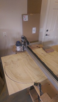
myOX : a 4' x 2' OX with potential

Discussion in 'CNC Mills/Routers' started by Serge E., Jun 19, 2014.

  1. Paruk

    Paruk Journeyman
    Builder

    Joined:
    Jul 13, 2014
    Messages:
    397
    Likes Received:
    149
    I see what you're up to! That's not a bad idea at all. A bit like the brushy thingy that you put behind the opening of your mail box.;)
     
  2. GrayUK

    GrayUK Openbuilds Team Elder
    Staff Member Moderator Builder

    Joined:
    May 5, 2014
    Messages:
    1,668
    Likes Received:
    627
    You got it!

    Gray
     
  3. Serge E.

    Serge E. Journeyman
    Builder

    Joined:
    May 6, 2014
    Messages:
    730
    Likes Received:
    252
    How time flies especially at temperatures approaching -40 (wind chill factored in) ! Working in the garage is far less interesting than a warm cup of spiked coffee/ hot chocolat, the fireplace and a blanket ... not forgetting wife.

    The bungee cord trick is only good for shallow work; deep work will have the Z bounce upward instead of sliding downward ! It is best to set the 'idle delay' to "255" and have the steppers powered all the time. The NEMA 17 is handling the heavy router just fine when continuously powered. That settles that.

    As a teenager would say : I need to learn from my own mistakes. I should of remembered my reply : you should first learn from the mistakes of others, it's less painful to you and your loved ones ! As for the bungee cord, will have to check what '50 shades of grey' as to say about other uses ...

    I do have to tune the amps being fed to the NEMA 17 as it is getting quick hot even with garage at near freezing ! No, it won't help to warm up the garage ... at least not before a complete meltdown. Is there an easier way to get the amps 'just right' then trial and error with the pot adjustment ??
     
  4. Serge E.

    Serge E. Journeyman
    Builder

    Joined:
    May 6, 2014
    Messages:
    730
    Likes Received:
    252
    The next lesson learned is having a true flat spoil board squared with the tool ... parallel to the X and Y plane that is. Mine was off by about 2 mm, mostly along X axis, over the full 750mm x 1500 mm surface of myOX.

    To cut through a piece of material didn't really matter, short of digging a tad deeper in the spoil board. However, pocketing made the (fat) 1/16" (!) error quick obvious even for my aging eyes ... Even working with the 24" or so wide plexiglass for my dust shield made the error plenty obvious with the pockets.

    Then came the lesson that surfacing MDF will make for a lot, I do mean A LOT, of very fine dust. The first thing to try is levelling the good old fashion way : adjust the table / work surface ! Aside from the dust, surfacing over 20" x 48" with a 2" tool will take more time. Surfacing is also limited to the reach of the tool, not to mention the tool's ability to handle a 2+" bit. My router, no problem - a spindle, might be a big problem? Not to forget if you plan on sliding oversized material through your machine, the ENTIRE spoil board needs to be flat, not just what a tool can reach ...
     
  5. Serge E.

    Serge E. Journeyman
    Builder

    Joined:
    May 6, 2014
    Messages:
    730
    Likes Received:
    252
    Having made the few adjustments mentioned in previous few posts, things are running much smoother now.

    I had to order some new batteries for my camera as the existing battery did not hold the charge for more than about 30 minutes compared to over 60 minutes before. Until myOX, I hardly used the camera ...

    Which brings me to the limit switches.

    The limit switches are, aside for homing, just a second to last resort in case your OX looses its mind and tries to ram into the fence. Not quite what I expected from the software end : basically kills the job instead of giving you the chance to decide if continuing is worth a try.

    A tangent in an other build - the CNC xPro one, has sparked an idea worth pursuing. It should satisfy my intent: having adjustable 'fencing' for myOX. That is, when I want to use it as an engraver, the limits can be as wide as I want (X and Y towards their physical limits) with Z bound to the 1 or 2 inches required. However, when I work a mold, I want to limit X and Y to the opening in my work table and allow Z to go as deep as I (it) can. That w/out killing a run if I forgot to adjust my 'limits' or whatnot.

    The suggestion received in the CNC xPro discussions should work and be relatively simple to execute : have a set of limit switches/sensors wired in parallel and connected to the 'pause' trigger with an 'override' switch to 'continue', if so desired. The software stays as is. The hardware is 'enhanced'.

    Time to put on the long johns and a tuque ...
     
  6. eagle2284

    eagle2284 New
    Builder

    Joined:
    Sep 8, 2014
    Messages:
    11
    Likes Received:
    3
    Serge, How has your build progressed so far? I wanted to share the progress I made to my machine this weekend because my design is inspired in part by yours.

    I have finished modifying my machine with the dual belt and pinion design as suggested by Tweakie.
    I found a belt intended for a GE cloths dryer that was 1/4" wide and approximately 3/16" thick That I placed inside the v-groove and secured using contact cement, to which I placed a GT2 belt with the teeth facing up - also secured with contact cement. Backlash in both the X and Y axes have been reduced from a few millimeters to a few microns over the the length of 1500mm and 1000mm, and repeatability is now sub-microns! Dial indicators are so much easier to use than dial calipers - I just wish I could find one in microns that was remotely the cost of imperial..
    I have checked the surface of my freshly built table (multilayer birch plywood framing with a 3/4 particle board top) and found it to be flat within 20 thou over the entire work surface, which I am pleased with thus far. I will be able to shim that and adjust it until I can get to my goal of less than 4 thou difference across the entire table. Even though the table is more than 100 lbs and built like a rock, my machine rapids fast enough to move more than I would like.

    Still trying to figure out what to do about the torsion on the X Axis. It is the weakest part of the machine right now. I picked up a can of fiberglass resin and a sheet of fiberglass that I will be testing to fill in the cavities of the extrusions on spare pieces of v-rail. I have also considered cement crack filler and anchor cement.

    Anyways, thank you for sharing your ideas!

    -Eagle
     
    #276 eagle2284, Mar 8, 2015
    Last edited: Mar 9, 2015
    sgspenceley, GrayUK and Jestah like this.
  7. Serge E.

    Serge E. Journeyman
    Builder

    Joined:
    May 6, 2014
    Messages:
    730
    Likes Received:
    252
    I have not spent much time on it, short of moving it around the garage to find a permanent home the wife could live with. It was excessively cold in the garage.

    It is an interesting approach which seem to work wonders. I'll have to give it a try. Actually looking t the various belt types offered through BRECOflex. No idea what they go for, but some interesting variations and lots of width options.
    The contact ciment might be a bit much if you have to change the belts at some point, no ? Lots of folks appear to find good quality double sided tape as plenty since it is just to keep the bottom belt from moving about.

    Wow, it does seem to work wonders, eh ?

    Fantastic. I'll have to work on my table as well. I used some left over OSB, but that is far from smooth or precise. I also need to think about the opening (bottomless table) concept to work mold forms with myOX. I'm thinking of getting rid of the two lengths of V-slots spanning / supporting the Y 'rails'. The later could be fixed directly onto the table. It would give an extra inch or so of work depth ...

    Well, I have a though on that but I need to play with the concept. Basically, the router, especially the heavier ones like mine, are out hanging (cantilevered) which can only put a twisting force on the X beams. These OX(en) not being heavy duty CNC machines, they need a bit of help. Why not have a bridge, like those container cranes : the router would be between two spans (possibly doubled) ...

    I'm also working with a local extrusion company to get 40x60 and 40x80 profiles at a reasonable price. So far, it looks quite possible even in 'small' production runs (that's about 250 Kg worth at a time). I don't personally need 250 Kg of extrusion... I could get some longer length then 1500 mm and even factory anodizing. I have talked with Mark about this a while back. No one seems to take lead on such larger profiles. Is there enough demand ? I will work the cost numbers again when I get back from my trip given aluminium prices are based on the US$ and the CND$ has dropped quite a bit since I last did pricing (it was for existing profiles) ... shipping the heavier, especially if over 1500mm, beams might be tricky (and expensive). I'll look into it when I get back from down South.

    It's the least I can do since I have learned from others through their sharing.
     
  8. GrayUK

    GrayUK Openbuilds Team Elder
    Staff Member Moderator Builder

    Joined:
    May 5, 2014
    Messages:
    1,668
    Likes Received:
    627
    Serge and Eagle2284.
    I have often thought about, and wondered why, OpenBuild doesn't supply the bits and pieces to make a Heavy Duty Ox.
    It seems, the common path for builders, is to produce an Ox, then decide to build a heavier and beefier machine for what they really want to do.
    My first thoughts are, that Mark and Co have more than enough to do with the Ox in it's natural form, and I can understand that moving on to another Model would be tempting fate as far as supplying materials.
    However, my thoughts, like yours, Serge, are that there are already many larger, heavier, beefier, slotted aluminium extrusions out there for the taking.
    If we, as a Forum, could decide on a specific type and style, say, a 50mm x 100mm, for the "Y" axis, and a 100mm x 100mm, for the "X" axis, which is available Worldwide. They don't have too Post it to us.
    OpenBuilds could take all the dimensions and produce the same bits and pieces, but bigger. Like bigger wheels for the wider slot, wider and stronger belts and Pinion wheels, for the same.
    Just the use of a piece of 100mm x 100mm as the "X" axis on the normal Ox would sort out the flexing problem right away. The discussions with regard to flexing would almost be a thing of the past.
    High end and stronger Stepper motors, such as the Nema 23 4nm, and even the Nema 34's are now much more available, and at reasonable prices.
    I know the Plate Guys would turn out the needed Gantry plates and other bits before you can say, "Bring it on!"
    So, I think it is a natural step, for CNCer's like ourselves, to want to move in that direction. If OpenBuild went in the same direction, then with their support, they would make it so much easier for us all, to go down a similar path.
    But, let's face it, where would we all be, if it weren't for Openbuild? Not at this place, or enthusiastic mind set, with regard to CNC. So, I'm NOT saying I'm dissatisfied in any way, with the OpenBuild philosophy or it's generation of great ideas and products. I guess, like yourself Serge, I'm just trying to nudge it towards another natural direction.

    Cheers
    Gray
     
    sgspenceley likes this.
  9. eagle2284

    eagle2284 New
    Builder

    Joined:
    Sep 8, 2014
    Messages:
    11
    Likes Received:
    3
    If I want to change the belts to a different type, I can flip the rail over and use the other side. I figure I have two chances, and if I need more than that, its time to upgrade to ballscrews. :p

    I've considered a redesign of the OX Plates to hold 80/20 30-6060 with the original 20*60 on top and bottom (if i kept the v-slots and wheel design). I do think the bridge idea would work, but I think you would still need doubles on both sides and it may make it more difficult to square up.

    Ive done work for the company that makes the dies for nearly all aluminum extrusion, and I know what the cost is that goes into just one of the dies alone. I'll purchase extrusions from someone that does it professionally and just make it work to my needs. Though, 250kg of extrusion could make quite a few go-karts and trebuchets

    When I ordered my first batch of v-rail a few months ago, I was shocked at how small it actually is, even though I looked at the dimensions a hundred times. But I think Open Builds are great as they are. Their v-slot is perfect for the entry level novice. If you are wanting to go stronger, you really should consider going with real linear rails instead of the v-slot design. Aluminum extrusion and Heavy Duty

    Also, enjoy some pictures :)
    20150309_181013.jpg 20150309_181214.jpg 20150309_181147.jpg
    (The bracket at the end of the rail will likely be modified to look pretty and not be in the way)
     
  10. Serge E.

    Serge E. Journeyman
    Builder

    Joined:
    May 6, 2014
    Messages:
    730
    Likes Received:
    252
    About to take off, so I'll make it (unusually) short.

    Good points and, like you, OBPS is the greatest with its vision and needs. However, lots are talking about needing beefier (or is it oxier ?) extrusion without the cost and limitations of the alternatives.

    Would going to 50x and even 100x better than 40x ? I will admit that the 40x is really just a small step up - replacing dual 20x. So we have to think about this a bit more. Do we go with just 40x, still affordable for most in our range of builds, or do we jump a few sizes & start looking at higher end hefty machines : Mega OX or OXpro types ?

    Well, I have to get to the airport. I will pick this up when I get back in a week or so ... unless I can get good enough Internet at resort ...
     
    GrayUK and eagle2284 like this.
  11. GrayUK

    GrayUK Openbuilds Team Elder
    Staff Member Moderator Builder

    Joined:
    May 5, 2014
    Messages:
    1,668
    Likes Received:
    627
    Have a good one mate!!
     
  12. eagle2284

    eagle2284 New
    Builder

    Joined:
    Sep 8, 2014
    Messages:
    11
    Likes Received:
    3
    I want wheels and bearings that accept an M8 bolt! Perhaps the 608ZZ 8x22x7 - a common bearing for skateboards and roller blades. The M5 bolt is just too flimsy imho.

    One thing to keep in mind is OBPS is cheap because the extrusion is small. If you are doubling the dimensions (ie. 20*40 to 40*80), you are not doubling the weight, you are quadrupling it. Weight is a big factor in the cost of extrusions and by the time you quadruple the price of OBPS, you are looking at the same price as other manufactures.

    I already have it in my head that I am going to be sourcing my aluminum extrusions from 80/20 and, if I dont use proper linear rails, I can still bolt v-slot or v-rails and not notice a difference.

    Safe travels!
     
  13. eagle2284

    eagle2284 New
    Builder

    Joined:
    Sep 8, 2014
    Messages:
    11
    Likes Received:
    3
    So I have done some test cuts after making all of the modifications to my machine. I am not happy...

    The torsion problem I was having before is better, but still unacceptable. In fact, I am beginning to think that the problem is still elasticity of the belts on the Y axis because I have measured that play directly now. I did say before that the belt and pinion design helped - it did! BUT I am still getting about 35 thou of elasticity on just the tiny amount of belt raised over the pulley. Ive even tried making the belt so tight that it wants to jump teeth on the pinion under the wheels.

    Im scrapping the belts on the Y Axis, shaving my Y rails from 1000mm to 900mm, and waiting for the part store to get more 1m lead screws in stock...:banghead:
     
    #283 eagle2284, Mar 11, 2015
    Last edited: Mar 11, 2015
  14. Rick 2.0

    Rick 2.0 OpenBuilds Team
    Staff Member Moderator Builder Resident Builder

    Joined:
    Dec 20, 2013
    Messages:
    2,892
    Likes Received:
    1,551
    8x16x5 bearings to fit the current V-wheels on an M8 hub are available in the parts store. Regular 5/16(8.1mm) x 1/4" spacers can be found here. For 8mm eccentrics however, you're on your own.
     
    Serge E. and eagle2284 like this.
  15. Florian Bauereisen

    Florian Bauereisen Well-Known
    Builder

    Joined:
    Feb 24, 2014
    Messages:
    188
    Likes Received:
    60
    Hi,
    a late reply about the heavy extrusions:
    Simply use the bosch / Item compatible aluminum extrusions.
    There is a wide variety to be had... the 90/90 (heavy vers.) would just nicely fit a 9mm wide belt into its 10mm "cutout" for a belt on belt design (for the x beam) while a 80...160/40 (heavy vers.) would make awsome sides for y. The belt could run on a simple alum. l-shaped pice bolted to the sides.
    Of course the design would have to be slightly changed to accept the different parts but the idea behind the ox could be carried on..
    Should not proove to hard as accurat dienional drawings are offered.

    Or even change to a slightly varied design which would offer even better strengh by eliminating the upward sideplates alltogether.
    For both just have a peek at my UE router thread for a better understanding what i am talking about...

    greets

    flo
     
  16. Florian Bauereisen

    Florian Bauereisen Well-Known
    Builder

    Joined:
    Feb 24, 2014
    Messages:
    188
    Likes Received:
    60
    One more thought ... ore two...

    A bigger extrusion of course uses more aluminum and thus it is more expensive...but buying them double and tripple wont make an ox cheaper either.
    While still not beeing satisfied....
    So here comes another thought: space two of your standard extrusions appart, as far as you dare, and bolt some cheap steel plate to it...maybe even use these little "block sliders" ( the ones that have a threaded hole in them -sorry i am not a native english speaker) in order to to create a box.
    As most of us already know, the further appart one spaces your supports ( as long as they are connectet) the stiffer the setup.
    This would mean only a slight change over to the original sideplates - mainly beeing slightly "higher" and two rows of holes to accept two extrusions laying flat.
    And yes the spacers and threds yould need a changeover - depending on the steelplates used.
    As i am metric i will not have a closer look at it, but surely spacers bolts and threds can be sourced acordingly.

    greets

    flo
     
  17. Rick 2.0

    Rick 2.0 OpenBuilds Team
    Staff Member Moderator Builder Resident Builder

    Joined:
    Dec 20, 2013
    Messages:
    2,892
    Likes Received:
    1,551
    If you are looking at built-up sections to increase the gantry stiffness, consider aluminum tubing. As all the material is concentrated at the perimeter it gives better flexural stiffness and torsional resistance than an equivalent weight of rail type extrusions. It should also be less expensive and in metric countries, readily available in sizes that match V-slot rail widths.

    Builtup.jpg
     
    GrayUK and sgspenceley like this.
  18. future_cncist

    Builder

    Joined:
    Feb 20, 2015
    Messages:
    38
    Likes Received:
    7
    This fellow has an interesting solution to adding rigidity to the x axis also , and it retains an opening for the cabling.
     
  19. Serge E.

    Serge E. Journeyman
    Builder

    Joined:
    May 6, 2014
    Messages:
    730
    Likes Received:
    252
    Actually, going from a 20x80 to a 40x80 (doubling the footprint of the profile) does NOT quite double the surface area nor the weight as the profiles should be tweaked (voids, etc.) As I work on a few 50x profiles, it turns out they can be nearly the same weight, if not a tad lighter (!) than the 40x while mounting exactly has the 20x and 40x (no changes needed in the plates) with the appropriate design and not loose any strength (or even gain on that aspect).

    If you look at the profiles of other manufacturers, especially the larger profiles, there is a lot of space. Some of those profiles are being designed to minimize weight bringing 'strength' to bare minimum required for the intended use, not always what we think or use them for ...

    As such, it is still possible to be quite competitive with the other manufacturers even without going to their production level (!!) Like a customs officer got me looking into the numbers, people are quite misled into the costs of the material, the production and subsequent distribution all the way to the consumer of just about everything. This is what makes Open Source Hardware a reality... It is also what allows aluminum to be smelter here in Canada, sent to Asia in slabs (or whatnot) for further processing into goods (like pots and pans) which are sold back to us cheaper than if those goods were made here at home.

    OBPS is doing a great job and, contrary to other manufacturers, is not out to make a quick dollar (but still needing to make a living and pay bills). The product fits a 'niche' market quite well. But the market is looking for a beefier profile rather than drill, glue, weld, etc. a few smaller pieces together.
     
  20. Serge E.

    Serge E. Journeyman
    Builder

    Joined:
    May 6, 2014
    Messages:
    730
    Likes Received:
    252
    I just submitted the RFQ for the 50x profiles (50x60 and 50x80, considering a 50x100) as the 40x profiles are more like a bandage. The 50x profiles will mount and can be used as the existing 20x or planned 40x extrusions adding a few features given the extra width. More info to follow in the coming week or two ...
     
  21. eagle2284

    eagle2284 New
    Builder

    Joined:
    Sep 8, 2014
    Messages:
    11
    Likes Received:
    3
    I look forward to seeing this. There is a good chance I will be bugging you to buy some :)
     
  22. Serge E.

    Serge E. Journeyman
    Builder

    Joined:
    May 6, 2014
    Messages:
    730
    Likes Received:
    252
    Sounds good. I am just waiting for the extruders' engineers to give feedback, they'll tweak the profiles, and initial quote for each mold and various volume.
     
  23. Serge E.

    Serge E. Journeyman
    Builder

    Joined:
    May 6, 2014
    Messages:
    730
    Likes Received:
    252
    For the 'custom extrusion', turns out the relatively local extruder is not so great on most if not all fronts. I also need to revise the profile to make it even lighter without loosing strength/rigidity. I am moving along learning some of the tricks of the trade ...
     
  24. Serge E.

    Serge E. Journeyman
    Builder

    Joined:
    May 6, 2014
    Messages:
    730
    Likes Received:
    252
    Work kept me busy, health kept me from doing all I had planned and life just kept going ...

    As for myOx and the goals I have from the get go, I have experimented and discovered, as a few "told you so" will confirm, some of the ... limits.

    First, that not so little NEMA 17 stepper used for the myOx's Z axis just can't keep up (literally!) with the heavy router I chose to use.

    Keeping the stepper powered all the time did make a great difference - the Z no longer slides down on its own. However, it gets real hot - can't touch it hot ! It was not a real bad problem in the middle of a frigid cold winter in a unheated garage. Not so good as the temperature did climb over the last couple months. myOx would run fine for a good 20 or so minutes and then, out of no where, the router would dive deep !! The driver, heatsink in place, was fine. The stepper was way too hot and would take for ever to cool down. I figure it was just letting go ... heat stroke ?

    The fix is easy : get a bigger (more appropriate) stepper motor ! That's one "told you so" that rang in my ears : do not skimp on the stepper motors.

    So I ordered a NEMA 23 - the single shaft version of the StepperOnline supplied steppers used for my X and Y axis. This one is the 23HS30-2804S with 269 oz/inch (compared to around 70 0r so of the NEMA 17). Best of all, the NEMA 23 was available through Amazon(.ca) which made it appear on my front steps < 48 hours after clicking 'order'. Cool ...

    Wait, that was too easy, right ? I forgot about the Z plates and a few other tweaks to hook up the larger stepper. So now I am waiting for a those few parts from OBPS. I should of checked with a few Canadian folk heres, like Robert et al.
     
  25. Jonny Norris

    Jonny Norris Well-Known
    Builder

    Joined:
    Aug 17, 2014
    Messages:
    495
    Likes Received:
    95
    I'm surprised your motors getting as hot as that. What current was you running? But Certainly sounds like you need a nema 23 if it's purely down to a weight issue.

    Nema 23's 3nm on a decent ball screw can lift 60kg or more vertically, I have two moving a 250kg gantry and they do it with ease and stay relatively cool. Think they are rated a max temp of 130 degrees Celsius. mine get to around 60 I'd say.

    You can get drivers with half current output on standby. This is quite effective at reducing the temperature of your motors.
     
  26. dddman

    dddman Journeyman
    Builder

    Joined:
    Mar 2, 2014
    Messages:
    468
    Likes Received:
    187
    The nema23 will work fine when it will be powered ON... I'll upgrade mine with a dual shaft one. On the second shaft I'll add a magnetic brake (magnetic when unpowered (also known as a clutch)). So when I power down the CNC or have a Estop, it won't dive in my parts... ;)

    For that second part, yes you should have :p I have at least one in stock :)
     
  27. Serge E.

    Serge E. Journeyman
    Builder

    Joined:
    May 6, 2014
    Messages:
    730
    Likes Received:
    252
    Then came the issue of going deep. I was and still am looking at working on parts about 6" deep ... if not more.

    The biggest issue I ran into while doing tests, each going deeper and deeper, is NOT the rigidity of the Z assembly. It's the physical profile of the tool - from the bit to the router to the Z axis holding it all.

    Most seem to do signs or cutting out parts out of 1/4" material, maybe 2.5D ... not much deeper than 1/2" for the most part. The standard Ox will do as much as 2" or so, which is plenty good for most needs. I'm aiming for going 6" or so deep !

    At first, I was using a ordinary router bit : 1/8" with, ya I know I should of figured this out earlier, a 1/4" shaft. The business end (1/8') was good enough to get the level of details I needed but it's less than 3/8" long before the 1/4" shaft gets in the way. Doh !! About an 1" (or less) up that 1/4" shaft the router gets into the picture - its shaft and then its body. I'll spare you the pictures as none were taken out of shame anyways. Lets just say it was not pretty ...

    I did have 1/8" bits with 1/8" shafts that are longer than the usual router bits. I even had a collet adapter so the router could safely use these bits. Wow, what a difference these long slender bits did. Now, I could easily go down 1" into a work piece with pretty good detailing (1/8" being the limit).

    Life was starting to smile back at me ...

    But how could I go 6"+ deep ??? There are a few, relatively expensive and either fragile or hefty bits with extra long shafts. They still would only allow to go a couple of inches, maybe 3" at best ... I could also go with a 5 axis machine to work around the geometry of the tool and work piece but that can get expensive. Think simpler ...

    I do have MeshCAM and it allows for a 4th axis by generating g-code for multiple faces ... a rotation of the work piece between each face.

    So how will I do 6" or so you may ask ? Well, turns out what I want to do (remember, shells for R/C 1/10 scale bodies) could be done mostly by working on the three faces (left, top and right). With doing 3" or so deep on each face giving me more than enough room to play. Only the top face might occasionally require deeper work. When it does, there should be enough room to get the router down an extra inch or so. The goal still seems attainable. Proper planning to account for router body / Z axis assembly size would help.

    There is no problems, just challenges ...
     
  28. Serge E.

    Serge E. Journeyman
    Builder

    Joined:
    May 6, 2014
    Messages:
    730
    Likes Received:
    252
    So it comes down to time - how long a job runs.

    It's nice and quick to 2D or even 2.5D a sign where the tool basically follows a bunch of lines, maybe going a 1/2" or so, probably doing most of the work in a single pass. Start adding shallow images, details, ... and it will take more passes, smaller tool, ... which all translate to taking more time.

    Now scale it up to a potentially 20 x 60 'sign', going as much as 1.5" deep while using the smaller diameter tool to avoid any tool changes. Well, roughing will take quite some time on it's own. A few more passes to clean up and get crisper / detailed results and you are in for a 20, 50 or more hours non stop ! Ridiculous, hey ? Especially when living in a lightning prone area (read power brown outs and outages).

    The use of multiple tools will become a must for the larger jobs, maybe do a few rough passes with a 1/2" bit (or larger) to quickly clean off extra material. Then have 1/8' bit to start detailing and going deep(er) with a finishing touch with finer still tools for precision engraving. However, time gained from roughing "big" will only get offset by doing finer detailing passes. It's like the trend of larger 3D printers - details, along with size, get in the way of run time.

    myOx capable of working on pieces nearly 60" wide and as long as one can slide through, think infinite in 20"x60" chunks, and it could get tedious indeed.

    Changing of tools, as the sliding of work piece, will need near perfect alignment. Zero the axis between a tool change or section ...

    For now, I'll be working on 1.5" x 20" x 60" projects :p As some have already pointed out, why not work layers (1.5") later glued together to build up as thich as I need (well beyond 6" if need be) ? Well, there is the issue of alignment, especially if I end up with many pieces on any particular level ...

    One step at a time, this is a hobby and I am in no (obvious) rush to get to where I want to be with myOx.

    I'll be back ...
     
  29. Jonny Norris

    Jonny Norris Well-Known
    Builder

    Joined:
    Aug 17, 2014
    Messages:
    495
    Likes Received:
    95
    You shouldn't require a brake, the z shouldn't drop unpowered. Something's loose by the sounds of it.

    Also during and estop you should only be killing any pulse signals being sent to your drivers. An estop should not power your drivers down. If you estop that way you will lose your position.
     
  30. Serge E.

    Serge E. Journeyman
    Builder

    Joined:
    May 6, 2014
    Messages:
    730
    Likes Received:
    252
    The NEMA 23 being used for X and Y are running cool. It's just the NEMA 17 which could be used to fry the morning eggs and bacon ...

    I kept tuning the amps down for the NEMA 17, but it would just not hold the weight of the router at that point. Poor thing is just not meant for the task. I'll use it for a smaller project ...
     

Share This Page

  1. This site uses cookies to help personalise content, tailor your experience and to keep you logged in if you register.
    By continuing to use this site, you are consenting to our use of cookies.
    Dismiss Notice