Welcome to Our Community

Some features disabled for guests. Register Today.

OX-SUMO, SUMO-OX, OXSUMO?

Discussion in 'CNC Mills/Routers' started by evildean, Oct 30, 2015.

  1. evildean

    evildean New
    Builder

    Joined:
    Oct 19, 2014
    Messages:
    26
    Likes Received:
    22
    evildean published a new build:

    Read more about this build...
     
  2. evildean

    evildean New
    Builder

    Joined:
    Oct 19, 2014
    Messages:
    26
    Likes Received:
    22
    Yes, I imagined I would need to build a cube with V-slot extrusion. The extra V-slot, plates, t-nuts, and bolts needed adds to the cost considerably! Initially the presumed benefit was an increase in cutting capacity, but the top of the Z-axis would contact the 40x40 cross member instead of the router bit. Might save me a router bit, but does not increase machine capacity!
    Current configuration allows for 28 inches cutting on the Y-axis, and 32 inches on the X-axis. X-axis potentially has an infinite capacity because you could continually feed material through sides. I could get another 2 inches easy if I put spoiler board on top of the 40x40 cross member, but I would need two 3 inch lengths of C-beam in place of the V-slot spacers I created to mate the Y-axis with the X-axis. The C-beam spacers would increase the Z-axis travel and are another modification I am considering regardless.
    Presently there is no perceptible deflection anywhere except on the Z-axis. Not enough to make the machine unsuitable for production... but present none the less! Side to side the Z-axis is solid, but if I grab the Nema motor on top I can realize some deflection front to back. This is probably the weakest point of the Openbuilds offerings, and I imagine any other entry level machine. Anyone address deflection on the Z-axis? I am open to thoughts, suggestions, ideas in that regard for sure.
     
  3. stargeezer

    stargeezer Journeyman
    Builder

    Joined:
    Feb 20, 2015
    Messages:
    328
    Likes Received:
    117
    Add a larger plate onto the existing z axis plate. Then add v-wheels above and below the C extrusion. More wheels, more rigidity.

    If you want to go as far as you can without adding linear rails, build a "cage" like you see on a Ox around the C beam.

    To me, the one shortcoming of the C-beam is the "narrow" spacing between the wheels on the inside of the C beam. A small amount of slop is really multiplied in your typical Z axis, as you are seeing. This is about the only shortcoming, but one you will need to address.

    Larry
     
    Tom Allen likes this.
  4. Florian Bauereisen

    Florian Bauereisen Well-Known
    Builder

    Joined:
    Feb 24, 2014
    Messages:
    188
    Likes Received:
    60
    Hi,
    it really doesn`t matter which direction your z axis deflects. Or any axis deflection that is.

    Any deflection of any axis will cause the bit to vibrate or say multiplies any vibrations.... this causes bit breaking .. in order to keep your bits intact you will have to mill slower than possible.

    This may not sound to bad but remember:
    You need to keep up (depending on material) a certain cutting load per tooth (chip load). Going much slower will transform the milling process into one of grinding heating the bits up greatly. Which the bits are not made for and break - again.
    So reduce spindle rpm to counteract... works up to the point where spindle doesn`t emmit enough torque to keep up and the bit stops and breaks again.

    That is one of the reasons one cannot build a cnc too strong, or in other words cnc machines are build generally very heavy looking at the small tools they use in the end.
    Hope this helps a little in understanding and leads you to adress your problems with some more backround.

    greets

    Flo
     
    Jestah likes this.
  5. evildean

    evildean New
    Builder

    Joined:
    Oct 19, 2014
    Messages:
    26
    Likes Received:
    22
    Thank you for taking time and sharing some experience with the new guy fellas! Always appreciated. I'm feeling your vibe Flo... I would much prefer a machine with zero deflection. Coincidentally I believe I may be taking your suggestion ala OX around the C-Beam Larry? I will post pix of my progress shortly. From what I have gathered, I maybe in the minority utilizing the OX model "cage" around the C-Beam, while retaining the gantry plate and mini v-wheels provided in the C-Beam bundles? (Not to be confused with the C-Beam Machine Kit!) I wonder if my description makes sense to many? I've got to get these pictures up. A thousand words and all that... :)
     
  6. evildean

    evildean New
    Builder

    Joined:
    Oct 19, 2014
    Messages:
    26
    Likes Received:
    22
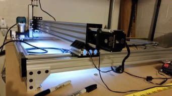
    All right, here is what I have right now. Preliminary result suggests I have not improved the aforementioned deflection on the Z-axis much? Maybe I need to preload the V-Wheels a touch more? Still I remain optimistic. It will be addressed! 20151104_192729[1].jpg
     
  7. evildean

    evildean New
    Builder

    Joined:
    Oct 19, 2014
    Messages:
    26
    Likes Received:
    22
    Larry mentioned linear rail earlier. It seems most logical to me.... What is the consensus on the inclusion of OpenRail?


    20151104_192520[1].jpg
     
    #7 evildean, Nov 4, 2015
    Last edited: Nov 4, 2015
    silopolis likes this.
  8. evildean

    evildean New
    Builder

    Joined:
    Oct 19, 2014
    Messages:
    26
    Likes Received:
    22
    Side note:
    The Makita trim router pictured is just setting in the too large mount I ordered from OpenBuilds. Anyone have a source for a couple of the spacers used for a 65mm router body with this mount? Shipping to zip code 53590 if possible. I qualify my next statement by mentioning I have better than 25 yrs. experience as a carpenter! That Makita trim router is so quiet just running in my hand.... that I think it may be broken? I will duct tape it to the Z if thats what it takes to cut something soon! Then there will be more questions. :)
     
  9. evildean

    evildean New
    Builder

    Joined:
    Oct 19, 2014
    Messages:
    26
    Likes Received:
    22
    Oh Yea, I forgot to include a picture of the workbench I assembled. Quick and dirty but I am very satisfied! Kreg jigged together for the most part,and I had all the tools and hardware already so $125 for materials at "Home Depot", and an afternoon later provided a crucial piece of the puzzle.

    20151102_190834[1].jpg
     
  10. tomulek

    tomulek New
    Builder

    Joined:
    Jun 8, 2015
    Messages:
    1
    Likes Received:
    0
    Hi, I'm no expert by any means but I think v wheels are designed to "stand up" on delrin/polycarbonate not be on their side. If I was building machine like this I would worry that delrin/polycarbonate would slip off bearings and hang on 8mm acme screw which at 1m is not very sturdy sideways... just my 2 cents.;)
     
  11. stargeezer

    stargeezer Journeyman
    Builder

    Joined:
    Feb 20, 2015
    Messages:
    328
    Likes Received:
    117
    I was wondering about that to, but it's the same position that The Beam has it's y axis in. If there is any way to rotate those rails into a vertical position, I know the wheels would be much happier.

    Doing that will also get you a bit more height under the gantry, which is always a good thing.
     
  12. Rick 2.0

    Rick 2.0 OpenBuilds Team
    Staff Member Moderator Builder Resident Builder

    Joined:
    Dec 20, 2013
    Messages:
    2,892
    Likes Received:
    1,551
    Increasing the vertical length of the grip would probably be the best suggestion. You might consider replacing the spacer blocks with the extended version that @Chris Laidlaw has to offer.

    There is a ridge on the inside wall of the wheels that prevent them from slipping off the bearings.
     
  13. evildean

    evildean New
    Builder

    Joined:
    Oct 19, 2014
    Messages:
    26
    Likes Received:
    22
    I agree with all of you. My mechanical senses tingle for all the reasons mentioned. My intent was to cut custom gantry plates, hopefully with this very machine, that will allow me to stand up the Y-axis beams and realize my intended vision for the machine originally. With an offset gantry I might gain up to 5 inches on the Y-axis? If the Y-axis beams are on edge instead of flat I also gain about 3 inches on the X-axis. I arrived at this point where I had to place my initial order from Openbuilds, because I needed something tangible in order to gain perspective, and explore these very limitations. In my efforts I am pleasantly surprised by the rigidity of the Y-axis C-Beams in this configuration! I would not have automatically considered this config. The exposed screws in this position make me nervous for obvious reason, but the strength where the X and Y connect is solid. I really need more time to analyze the situation, and better determine what piece or section is the root of my Z-axis deflection pushing front to back. Everything else in this temporary configuration feels rock solid!

    @Rick 2.0 Thank you for the link to Chris Laidlaw's stuff. I knew he was a source of gantry plates and such, but did not know about the eBay store with a convenient stock of very nice looking items. No way will I see results like that with my build... Wow!
    chrisclub1 on eBay
     
  14. Steven Bloom

    Steven Bloom Journeyman
    Builder

    Joined:
    Dec 18, 2014
    Messages:
    194
    Likes Received:
    105
    If you look under my Sea-Ox design there is a part called Sea-Ox Spindle Plate. It mounts to 20x80 or 40x80 C-Beam. It converts to attach a 65mm mount like the one I am using. But I am attaching file for you.
     

    Attached Files:

  15. Rick 2.0

    Rick 2.0 OpenBuilds Team
    Staff Member Moderator Builder Resident Builder

    Joined:
    Dec 20, 2013
    Messages:
    2,892
    Likes Received:
    1,551
  16. evildean

    evildean New
    Builder

    Joined:
    Oct 19, 2014
    Messages:
    26
    Likes Received:
    22
    @Rick 2.0
    Yes, that is the spindle mount adapter I was looking for. I just don't have any friends cool enough to own 3D printers. Truth be told, I probably do.... I should get out more! Thank you for the heads up. :)

    @Steven Bloom
    Thank you for pointing out the spindle plate. I had previously read your Sea-Ox blog with great interest, and had bookmarked your generous source of custom plates. Your design focus, maximizing the Z-axis travel, is of particular interest. I will look forward to your updates.
     
  17. evildean

    evildean New
    Builder

    Joined:
    Oct 19, 2014
    Messages:
    26
    Likes Received:
    22
    I continue assessing the deflection I see on my Z-axis, and I want to say the Openbuilds gantry plates I've used are the source for much of it?

    Zaxis_side1.jpg

    I think I may improve some if I flip the X-axis beam over so the screw faces forward. That way my Z-axis would bolt through to the C-beam gantry plate with the added benefit of its four mini v-wheels. Does that make sense?

    Zaxis_side2.jpg

    Also I think I really want one of these... CNC Router Mount and Dust Collector Kit :D

    [​IMG]
     
    #17 evildean, Nov 7, 2015
    Last edited: Nov 7, 2015
    silopolis likes this.
  18. Florian Bauereisen

    Florian Bauereisen Well-Known
    Builder

    Joined:
    Feb 24, 2014
    Messages:
    188
    Likes Received:
    60
    Hi,
    bringing the x and z screw to one side is always a good idea. There is little leverage like that and that is always preferable.
    Question is: are there enough holes left to mount Screw and z-assembly?
    Will you be able to assemble it still?
    Might be worth to first finish the machine as designed and than do mods yourself.

    Greets

    Flo
     
  19. evildean

    evildean New
    Builder

    Joined:
    Oct 19, 2014
    Messages:
    26
    Likes Received:
    22
    @Florian Bauereisen
    Thank you for the encouragement. It will require some assembly tweaks to put all on the one side. Im still trying to find time for it though. I will post an update soon. :)
     
  20. stargeezer

    stargeezer Journeyman
    Builder

    Joined:
    Feb 20, 2015
    Messages:
    328
    Likes Received:
    117
    I'm really glad you posted the pics. Those openbuilds plates are not strong enough for this kind of duty in my mind. Too many holes and far too thin result in flex. You will find that about everybody uses plates that are 1/4" plus thick and switch to the transparent wheels for maximum rigidity. Switching to steel rails and wheels would be the next step up before going to supported linear rails and bearings.

    I seriously think your best bang for your buck would be to get a set of cut plates - your machine is about strong enough to cut them yourself, or you might purchase a set from one of the guys here that produce them. 1/4" + thick - no skinny plates.
     
  21. evildean

    evildean New
    Builder

    Joined:
    Oct 19, 2014
    Messages:
    26
    Likes Received:
    22
    @stargeezer
    I have come to the same conclusion. Honestly I'm not sure the Openbuilds plates are worth using for anything! As you noted too many holes and far to thin. I will be purchasing better build plates for sure! Sucks because I have realized my estimate of $1400 usd. Any additional dollars spent are over budget. Maybe I should have considered the "V-Carve" kit from "Inventables" after all...?
     
  22. stargeezer

    stargeezer Journeyman
    Builder

    Joined:
    Feb 20, 2015
    Messages:
    328
    Likes Received:
    117
    I would NOT agree with you on that. I purchased and built a Shapoko 2, just two weeks before the V-Carve came out. I was VERY underwhelmed with it. Their plate thickness was the same. Of course they did improve most of the worse problems that I noted and most complained about except the plates and the mass of the rails. I think that aside from the plates you used in the X axis, the open build C rails are great building blocks to base a machine around. They are good engineering.

    The Open Build plates are what they are - prototype plates. If you want to mock up a build to see exactly how things are going to work, they are fine. If you have a area that has no real stress, such as the end plates of the Y axis, they are fine. Using them to support the Z axis screw/endplates is ok too since they are very small, but my son and I both have managed to bend those too.

    If I were you, I'd get the machine running, do all the steps you need to in order to become comfortable with what you have there and then purchase or cut replacement plates for the X axis. I'm certain it's tight enough to do that. The investment you've made is sound and you really have made good decisions.
     
  23. evildean

    evildean New
    Builder

    Joined:
    Oct 19, 2014
    Messages:
    26
    Likes Received:
    22
    @stargeezer
    My previous post does sound a bit harsh. Your perspective and description of the openbuilds plates is magnificent. I absolutely agree! After some careful thought and reconfiguration I have eliminated much of the deflection despite the limitations. Now its mostly the C-axis beam twisting, but it is still much stiffer. I will post some pics again shortly. I have also contacted Chris Laidlaw for some of his offerings. The stuff in his store looks amazing! Made in the USA!!! Affirmation is the best fuel for motivation. I'm sorry for your experience with the Shapoko. I am grateful for your honest critique. Thank You.
     
  24. evildean

    evildean New
    Builder

    Joined:
    Oct 19, 2014
    Messages:
    26
    Likes Received:
    22
  25. evildean

    evildean New
    Builder

    Joined:
    Oct 19, 2014
    Messages:
    26
    Likes Received:
    22
    If looking closely you may notice the V-slot is stationary in this configuration. Only the router, router mount, gantry plate assembly move up or down the Z-axis. The end plate on bottom of the V-slot is stationary also! The router case (top) will run into the Nema motor plate above! I'm going to run some test/example codes in wood anyway. I'm very excited!
     
  26. evildean

    evildean New
    Builder

    Joined:
    Oct 19, 2014
    Messages:
    26
    Likes Received:
    22
    E... thats Eccentrics not concentrics! I'm such a boob! :p
     
    stargeezer and Joe Santarsiero like this.
  27. stargeezer

    stargeezer Journeyman
    Builder

    Joined:
    Feb 20, 2015
    Messages:
    328
    Likes Received:
    117
    I haven't heard too many grammar and spelling masters browbeating people here (unlike some forums I've visited). We all understand and have stood in your shoes from time to time to time. (I've got to fix that stuttering keyboard). :)
     
  28. Anthony Webb

    Builder

    Joined:
    Dec 30, 2013
    Messages:
    23
    Likes Received:
    2
    I am contemplating doing a pick and place in much the same fashion you did this CNC. I am curious, you have a spacer block between the x and y cbeams. Were those not able to be attached together without the spacer block? Or were you just trying to get a little more height? Also curious why you didnt use a CBeam for the Z as well? Thanks!
     
  29. evildean

    evildean New
    Builder

    Joined:
    Oct 19, 2014
    Messages:
    26
    Likes Received:
    22
    The need to feed and support a family consumes me presently. Things are usually winding down around the holidays, so I am grateful for the work, but dad-gum I want to play CNC wannabe real bad!

    @Anthony Webb
    I think this configuration would work superbly as a "pick and place"! I am only just learning so most anything I share is from that perspective. You may be able to eliminate spacer blocks but the clearance between gantry plate and c-beam is limited. I had to add additional precision shim between plate and v-wheels, plus shim the plate and nut-block, creating just enough clearance for the 5mm bolt heads that go thru bottom of plate and up into the t-nuts slotted in the spacer block you referenced. Hope that made sense? The bolt heads, thin as they are, are beneath the plate. Riding back and forth just above the c-beam. Without shim addition they rubbed the exposed V-wheel slots scarring them. If you do the same and the bolts up through plate...... Nope you need the t-nuts to thread into. Unless you can put nuts on top? Like if you had a nut inside those black angle brackets? Not sure that would work? Just playing that out loud for your perspective. You will find a way make it yours that is for sure.

    One motivating factor for using the V-slot assembly on the Z axis was a desire to explore a V-slot bundle. I had three C-beam bundles already, and no prior experience with the hardware. Valuable decision too... for fact of revealing difference between a nut-block and the anti-backlash nut-block! V-slot bundle comes with anti-backlash nut... C-beam bundle has regular nut-block! I also thought the V-slot would get my router closer to the X-axis, but I'm not sure that is the case?

    Although limited experiments in wood have exceeded expectations, my attention has focused on rigidity.
    Not for necessity though! It's more like I'm tuning an engine to know or feel like I'm getting the most, or even more, from any given tool or machine. I probably don't need it... but I like to know it is there. :)
     
    silopolis likes this.
  30. evildean

    evildean New
    Builder

    Joined:
    Oct 19, 2014
    Messages:
    26
    Likes Received:
    22
    My first sign ever. Cheap 1/2 inch plywood I had laying around. Wishing I could get back all the scrap wood I ever threw away!

    20151115_133804[1].jpg
     
    Mark Carew and silopolis like this.

Share This Page

  1. This site uses cookies to help personalise content, tailor your experience and to keep you logged in if you register.
    By continuing to use this site, you are consenting to our use of cookies.
    Dismiss Notice