Welcome to Our Community

Some features disabled for guests. Register Today.

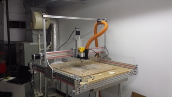
My CNC Router Built Around The New C-Beam Rail

Discussion in 'CNC Mills/Routers' started by Robert Bailey, May 30, 2015.

  1. Giarc

    Giarc OpenBuilds Team
    Staff Member Moderator Builder Resident Builder

    Joined:
    Jan 24, 2015
    Messages:
    3,008
    Likes Received:
    1,676
    That sign looks very cool.
     
  2. Mark Carew

    Mark Carew OpenBuilds Team
    Staff Member Moderator Builder Resident Builder

    Joined:
    Jun 28, 2013
    Messages:
    2,759
    Likes Received:
    2,438
  3. Robert Bailey

    Robert Bailey Well-Known
    Builder

    Joined:
    Mar 23, 2015
    Messages:
    117
    Likes Received:
    71
    this is the bit I used 10x Carbide PCB Acrylic ABS Copper Engraving CNC Bit Router Tool 30 Degree 0.2mm
    I had no idea what speed and feed to use so I just looked up the single flute spiral bit I got from tools today and tried their formula, 67 IPM 24,500 RPM and a DOC of .0156.
    didn't have any melting, had the air on and then used a stiff nylon brush to clean the grooves out.

    I picked up some of the .1mm in the 10,15,20,30 deg assortment pack. I do have the ToolsToday.com 1/4 and 1/8 up cut plastic bit which I used to gut the outside to shape, then used an oxy-map torch to flame polish
    the edges.
     
  4. Peter Oakes

    Builder

    Joined:
    Jul 12, 2015
    Messages:
    25
    Likes Received:
    19
    I too have been pondering this conundrum as Sam from SNB Solutions here in Ontario, Canada has kindly provided me an upgrade to my build which includes 80x40 extrusions for X, Y and Z axis, and while I dont yet have X axis plates able to mount onto an 80x40 gantry, I have the Z axis built like this
    [​IMG]
    If I mount the C section to the X gantry truck then I limit the usefull travel of the Z axis to basically the length of the router and bit extending past the end of the travel when fully lowered and and limit the height of the job to that where the bottom of the Z will impact the work but the coupling between the extrusion and the gantry will be verry good
    Mounting the Z truck to the X gantry plates allows the full travel of the Z axis but with the added weight of the Stepper and Z axis hardware.
    The biggest issue either way is that the truck shown is only 4 point contact with the wheels and there close together. I was simply going to add a second truck (Same size) and nut block to the axis more than doubling the surface to mount to and increasing the rigidity of the Z significantly.

    the second nut block would not always be needed but it would share the load nicely. if the plate was simply double the length with additional or more spaced out wheels, this would acheiv ethe same thing but then two nut blocks would not work probably due to getting the threads to connect

    anythin beyond the distance between the upper and lower X wheels would not add additional rigidity as the fulcrum would still be the 80,, X axis size + whatever the X plate takes away

    This is a 15" Z axis extrusion so quite long, therfor at full reach, you would not be able to put much load on the router bit before excessive deflaction is seen in the varions axis

    So in summary, I like the idea of bolstering the Z axis truck no matter which way the Z axis is mounted, the additional question is... which way is the best way ??
     
  5. Robert Bailey

    Robert Bailey Well-Known
    Builder

    Joined:
    Mar 23, 2015
    Messages:
    117
    Likes Received:
    71
    loaded question for sure, if you look at other projects you see many designs, me and my buddy Kevin are redesigning the Z-axis to incorporate the C-beam and using internal wheels pushing outward
    while having external wheels pushing in form the outside, we will eliminate the spacer block, I have new designs for the upper and lower Z , the lower will also have a vacuum port. I will go ahead and post the sketchup files but we haven't tested them out yet so don't take them a gospel . we use lauan plywood to do test fits, much cheaper than aluminum. everything is a work in process except the Y-axis end plates. keep in mind that I have upgraded the 8mm bearings, mine don't require a pocket and are 22mm in size.
     

    Attached Files:

  6. Peter Oakes

    Builder

    Joined:
    Jul 12, 2015
    Messages:
    25
    Likes Received:
    19

    I forgot to ask, the LUAN, is this the standard 5.x mm sub flooring kind of stuff, is this string enough to use or is this just to verify the pattern ?, for me this stuff looks to be about 20$ for a 4x8 sheet of 5.x mm
     
  7. Peter Oakes

    Builder

    Joined:
    Jul 12, 2015
    Messages:
    25
    Likes Received:
    19
    On the bottom Z plate am I correct in assuming the 22mm hoes are for your bearings, the 74mm hole for clearance of a bosch colt router (Or any 72mm ish router mounted) and the 65mm is for the vac. what is the 17mm for ??
    on the top Z plate, the 10.5mm hole
    it looks like the top Z plate extends out hte back of the gantry, im assuming to facilitate mounting a cable track, this also aligns as best I can see the two holes on additional tabs out from the main body

    there was no Z truck included, are you planning on mounting the truck to the X gantry or the C section 80x40 to the gantry?, as best I can see with the diagram, your mounting the C section to the gantry and allowing the motor to travel on the Z truck, this still leaves the conundrum about limiting the Z clearance this way :)

    In your re-design, are you planning on having more than 4 wheels on the inside, or atleast increasing their distance to improve vertical stability ?

    it also looks like your leaving behind the use of belts, GT3 or 3, nothing wrong with that for a more advanced machine needing more accuract too , is this your reasoning ?

    Thanks for the prompt reply btw, very informative
     
  8. Robert Bailey

    Robert Bailey Well-Known
    Builder

    Joined:
    Mar 23, 2015
    Messages:
    117
    Likes Received:
    71
    if you look on post 41, I posted a pic of bearings an clamps I will be using, the far left is the new bearing and the bottom left is the screw clamp. this build has no belts. the bottom plate will let me use the openbuilds router holder that I have and I will be able to screw it to the bottom while only having 2 angle brackets on top. the small 12.2 mm holes around the outside are for magnets , just noticed I had them inside cuts should be pocketed, working on this at home today, got the crud so my focus is a bit off. the 17mm hole will be the mount for air/mister the 63.5mm(2.5" ) is for the vacuum adapter. here is the X plates that currently ride
    on my machine minus the fancy cuts, I ma in the process of modifying the front to put the mini wheels on that plate to reside at the top and bottom on the inside. I just placed an order with mark last night for the c-beam. I plan or replacing the 20x80 Z movement with the C-beam. and flipping the Y 180deg to get the screw to the backside.
    here is more pictures to help you see what we are doing. I have plenty of pictures if you need more.
     

    Attached Files:

  9. Robert Bailey

    Robert Bailey Well-Known
    Builder

    Joined:
    Mar 23, 2015
    Messages:
    117
    Likes Received:
    71
    before I get hit, all the wheels have been replaced with extreme wheels. that was all I have when mocking it up
     
  10. SteveB05

    SteveB05 New
    Builder

    Joined:
    Nov 24, 2015
    Messages:
    5
    Likes Received:
    0
    Please excuse the extremely crude drawing, but I was thinking I could add Z-Axis rigidity by adding a set of wheels to run on the face of the C-Beam.
     

    Attached Files:

  11. Robert Bailey

    Robert Bailey Well-Known
    Builder

    Joined:
    Mar 23, 2015
    Messages:
    117
    Likes Received:
    71
    you could do that but that means your z axis beam is fixed, if I redesign the Z again, I am tossing the wheels and designing a rail system
     
  12. Peter Oakes

    Builder

    Joined:
    Jul 12, 2015
    Messages:
    25
    Likes Received:
    19
    ok, so an additional peice comming forward to mount additional wheels and provide even more rigidity ??, the triangle bit

    Using excentrics top and bottom would allow you to tun the alignment of the z to get it perpendiicular with bed... just a thought
     
  13. Peter Oakes

    Builder

    Joined:
    Jul 12, 2015
    Messages:
    25
    Likes Received:
    19
    here is a picture of a mount I designed for the Bosch / Dewalt (72mm hole) with additional holes for screwing in accessories, 3D printed in PLA, it is 40mm Thick and 100x100mm, here is the design and a pic, use it if it is any use to you, I plan on sharing anyway, I am also going to design a printable one for the 80x40 C beam, this one is for a 60x20 Z axis
    Bosch_Colt_Mount.png
     

    Attached Files:

  14. SteveB05

    SteveB05 New
    Builder

    Joined:
    Nov 24, 2015
    Messages:
    5
    Likes Received:
    0
    True! I was thinking an eccentric at the left most (in the drawing) mounting screw but I think your idea is better. Obviously @Robert Bailey is right that rails are the best solution. I have no other metal tools though so need to keep this something I can build with credit card and a hand drill :)
     
  15. Robert Bailey

    Robert Bailey Well-Known
    Builder

    Joined:
    Mar 23, 2015
    Messages:
    117
    Likes Received:
    71
    I have hand tools and a craftsman drill press, picked up and aluminum blade for the chop saw at home depot. we printed a 1:1 drawing and center punched and drilled the holes by hand. mow the machine is
    making its own replacements. Machines making machines.......judgment day.

    Sign #2 done for my nephew's Vape business.
     

    Attached Files:

  16. Peter Oakes

    Builder

    Joined:
    Jul 12, 2015
    Messages:
    25
    Likes Received:
    19
    very nice sign
     
  17. Robert Bailey

    Robert Bailey Well-Known
    Builder

    Joined:
    Mar 23, 2015
    Messages:
    117
    Likes Received:
    71
    well we are making some more progress, ran a test on the new z-axis top and bottom plates. got my c-beam in and cut, have planes to use it with 4 wheels internal at the corners. with the holidays it has been slow
    going. I have a couple of adjustments to make to the plates then its time to cut aluminum.
     

    Attached Files:

  18. Robert Bailey

    Robert Bailey Well-Known
    Builder

    Joined:
    Mar 23, 2015
    Messages:
    117
    Likes Received:
    71
    stayed late tonight and ran another test fit, almost ready to cut aluminum. fitted the Chinese mister, tested the magnet pockets and added the vacuum adapter, next cut will be a test fit for the X axis to be
    sure I have the internal wheel spacing correct.
     

    Attached Files:

  19. Robert Bailey

    Robert Bailey Well-Known
    Builder

    Joined:
    Mar 23, 2015
    Messages:
    117
    Likes Received:
    71
    busy weekend slinging chips, we cut the X and Z axis plates and doing a test fit, still working on the Y plates. having some issues with the cad/cam...mark is looking at my files on another post. If I can get the Y plates cut this week I will most likely dissemble the whole thing and rebuild with the new plates.
     

    Attached Files:

    GrayUK and SteveB05 like this.
  20. Peter Oakes

    Builder

    Joined:
    Jul 12, 2015
    Messages:
    25
    Likes Received:
    19
    What are you making the Y and Z plates to fit regarding the X gantry... 2 paired 60x20s or an 80x40 ??, cant quite tell from the plates you show
     
  21. Robert Bailey

    Robert Bailey Well-Known
    Builder

    Joined:
    Mar 23, 2015
    Messages:
    117
    Likes Received:
    71
    everything is for the C-Beam using acme screws, here is another test we did for the Y gantry. we do a wood test before we cut aluminum....cheaper
     

    Attached Files:

    #81 Robert Bailey, Jan 12, 2016
    Last edited: Jan 12, 2016
  22. Peter Oakes

    Builder

    Joined:
    Jul 12, 2015
    Messages:
    25
    Likes Received:
    19
    Thanks for clarifying, I had some of my viewers on youtube asking about cutting aluminium with a belt GT3 based CNC, it looks like your all screwy :)
     
  23. Robert Bailey

    Robert Bailey Well-Known
    Builder

    Joined:
    Mar 23, 2015
    Messages:
    117
    Likes Received:
    71
    yep, been that way for years, according to the little woman. I was just looking into building on when Openbuilds came out with the C-Beam so I decided to go that route.
    I still have reservations about the delrin block that drives the gantry, font know how long they will go before getting lots of backlash.
     
  24. Robert Bailey

    Robert Bailey Well-Known
    Builder

    Joined:
    Mar 23, 2015
    Messages:
    117
    Likes Received:
    71
    Stayed late at work last night and cut out the Y Gantry...almost ready to
     

    Attached Files:

  25. Robert Bailey

    Robert Bailey Well-Known
    Builder

    Joined:
    Mar 23, 2015
    Messages:
    117
    Likes Received:
    71
    well I made a boo boo on the Y plates, I completely forgot to check the screw block fitment on the wood mockup. I had the holes 15mm apart instead of 20mm......oops.
    took a few minutes to manually locate and drill new ones but we saved the plates. Tomorrow we will break the machine down and install all the new plates. here are a couple more pictures
    of the new stuff and a picture of a up lit sign I just finished for one of our departments ant work to sit in the booth at the trade shows.
     

    Attached Files:

    GrayUK likes this.
  26. Rick 2.0

    Rick 2.0 OpenBuilds Team
    Staff Member Moderator Builder Resident Builder

    Joined:
    Dec 20, 2013
    Messages:
    2,892
    Likes Received:
    1,551
    I note you have a remote setting with the sign. Are you using a specific electronics package or just a collection of parts on these?
     
  27. Robert Bailey

    Robert Bailey Well-Known
    Builder

    Joined:
    Mar 23, 2015
    Messages:
    117
    Likes Received:
    71
    Rick 2.0 likes this.
  28. Robert Bailey

    Robert Bailey Well-Known
    Builder

    Joined:
    Mar 23, 2015
    Messages:
    117
    Likes Received:
    71
    made them, I hand drilled the first plates then we had the cnc make its own replacements.
     
    Mark Carew likes this.
  29. Robert Bailey

    Robert Bailey Well-Known
    Builder

    Joined:
    Mar 23, 2015
    Messages:
    117
    Likes Received:
    71
    you never get the amount of work done when a blonde is helping you
     

    Attached Files:

  30. Peter Oakes

    Builder

    Joined:
    Jul 12, 2015
    Messages:
    25
    Likes Received:
    19
    While were talking about ball screws and the like.

    Does anyone know where I can get a model or STL file of the Antibacklash 8MM nut block. All the ones I have found so far do not included the threaded portion of the ACME Screw. I am being sent a sample of a new Filament to review, it is meant to be low friction but 50* more resilent (Wear Resistant) than PLA so I want to print one of these to test, and also modufy the model to include mounting on bigger plates or even include in a X plate. Of course any models I create will be shared with the site

    Oh, its the 8mm ACME Screw version I need

    Thanks in advance

    Peter
     

Share This Page

  1. This site uses cookies to help personalise content, tailor your experience and to keep you logged in if you register.
    By continuing to use this site, you are consenting to our use of cookies.
    Dismiss Notice