Welcome to Our Community

Some features disabled for guests. Register Today.

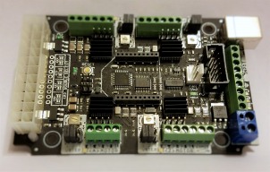
CNC xPRO Driver

Discussion in 'Other Builds' started by Spark Concepts, May 25, 2014.

  1. snokid

    snokid Journeyman
    Builder

    Joined:
    Oct 11, 2014
    Messages:
    335
    Likes Received:
    104
    Did you check your power supply with a VOM?
    The diode rating doesn't matter so much. Go out trash night and pick up an old vcr, tv, printer.... They all will have a diode in them.... if there isn't a supply house by you...
    What can happen if you don't put the fuse and diode in is in the event your power supply goes bad it could take your cncxpro board out... .20 of protection or 120.00 to buy a new board....
     
    #421 snokid, Jan 9, 2016
    Last edited: Jan 9, 2016
  2. azarock

    azarock New
    Builder

    Joined:
    Oct 11, 2015
    Messages:
    21
    Likes Received:
    5
    Thanks for the video on z axis probing snokid, I had no idea the XPro could do that. :cool:
     
    snokid likes this.
  3. Rob Mitchell

    Rob Mitchell Well-Known
    Builder

    Joined:
    Nov 29, 2015
    Messages:
    105
    Likes Received:
    35
    Are you guys using more than one limit switch per axis (one on each end) or just a single switch with software limiting?
     
  4. snokid

    snokid Journeyman
    Builder

    Joined:
    Oct 11, 2014
    Messages:
    335
    Likes Received:
    104
    I don't use either. They aren't needed in my opinion....
    But most guys use 1 per axis then software limit, I think....
    The first few days of learning your machine you will drive the thing to the ends and past, it's no big deal.... Don't make a habit of it...
    just hit your stop and figure out what you did wrong, no harm no fowl....
    after you learn the lingo and your machine it's never a problem.
    I can't remember the last time I goofed.... and if I do the motors just stall till they reach the end of that code.

    So how it works is you design a part and make gcode.
    Then you put material on your machine.
    then you zero out your machine.(can be done by hand)
    press play
    part is cut
    machine returns to where it started(home)
    if you want put more material down on your machine and hit play again....
    in all that where do the limit switches help?

    Not raining on your parade just stating what I do, take it for what it's worth....
     
  5. Steve Fox

    Steve Fox Well-Known
    Builder

    Joined:
    Feb 22, 2015
    Messages:
    129
    Likes Received:
    21
    I use limit switches because my machine doesn't know where it is when it starts up.
    Even if it did, if I moved it, it would think it was someplace else.
    With the switches, when I tell it to go home, it knows exactly where it is.
     
  6. Rob Mitchell

    Rob Mitchell Well-Known
    Builder

    Joined:
    Nov 29, 2015
    Messages:
    105
    Likes Received:
    35
    But do you have just 3 switches, one per axis or did you put two on each axis (one at each end)?

     
  7. snokid

    snokid Journeyman
    Builder

    Joined:
    Oct 11, 2014
    Messages:
    335
    Likes Received:
    104
    Steve
    What is the point? Do you always hold the material down in the same place?

    What I do is hold down the material I'm going to cut, then I zero the machine at the lower left corner of the material, which now becomes home. Then I hit start.
    So if I have a 12" x 24" piece of lexan on the machine, but I have already used some of it up, I can zero the machine anywhere there is enough material to cut the part I want to make.

    My take on always having the machine go to the lower left as home, then you still need to set work offsets. Kind of the same thing just a different way to the end.

    Maybe I'm missing the importance of homing switches.
    Bob
     
  8. John Meikrantz

    John Meikrantz Well-Known
    Builder

    Joined:
    Nov 2, 2014
    Messages:
    169
    Likes Received:
    56
    I have three switches, one per axis. I find it very useful to be able to home the machine and have a predictable zero. Soft limits are set to keep the machine from exceeding the machine envelope.
     
  9. Steve Fox

    Steve Fox Well-Known
    Builder

    Joined:
    Feb 22, 2015
    Messages:
    129
    Likes Received:
    21
    Yes, my zero point is always the same and it isn't the home position. I have switches on both ends of X and Y and top end of Z. Occasionally, I exceed the allowable X and the machine stops. One project I was working on, I needed every 1/8" of X that I could get. It took me a couple of times to get that worked out.

    I like having the home switches because if one of the motors skips a couple of steps, it shows up in the coordinates of my Home point.
    I see how you could get along without them, but I prefer having them there. I installed them after banging into the stops a couple of times when I was first calibrating the machine.
     
  10. snokid

    snokid Journeyman
    Builder

    Joined:
    Oct 11, 2014
    Messages:
    335
    Likes Received:
    104
    Thanks Steve
    Makes sense.
    So how do you do it?
    home is something like -10x -10y?
    then zero is just off from that?
    Can you kind of run thru the process?
    thanks Bob
     
  11. Steve Fox

    Steve Fox Well-Known
    Builder

    Joined:
    Feb 22, 2015
    Messages:
    129
    Likes Received:
    21
    My home position is actually off of the front of the table. It is someplace around X=-0.25, Y=-2. I built it so I could cut vertical pieces of wood if I ever want to by pushing the table back slightly.

    I have two pieces of .75"x1.5"x24" MDF on the front and left side of the machine with the inside edges at what I call my zero point. I program that using G28.1 to set it and G28 to go there. I also use G30.1 and G30 to send the router out of the way when I'm done with a job. It goes someplace around X=0,Y=24.

    For some reason, the way GRBL works, if the motor skips any steps, my home position coordinates change, but not my zero point coordinates. I'm not sure why that is. If I go to 0,0 after it skip steps, the coordinates say 0,0, but the point is off. I can tell when I skip steps because the home position coordinates are off by whatever steps were skipped and I have to reset zero by using G28.1.

    I had originally figured that the home position would always be the same since the microswitches don't move, but that isn't the case. I gave up trying to figure it out and just learned to deal with it.

    Hope this helps.
     
  12. snokid

    snokid Journeyman
    Builder

    Joined:
    Oct 11, 2014
    Messages:
    335
    Likes Received:
    104
    thanks Steve.
    I need to mount some switches and give it a try.
     
  13. azarock

    azarock New
    Builder

    Joined:
    Oct 11, 2015
    Messages:
    21
    Likes Received:
    5
    Anyone experience false hard limit alarms before? Seems to be when I am vacuuming saw dust up if I touch the machine frame it gets a jolt of static electricity and feeds back to the board as a hard limit alarm and it quits. Anyway to ground this out so that doesn't happen?
     
  14. snokid

    snokid Journeyman
    Builder

    Joined:
    Oct 11, 2014
    Messages:
    335
    Likes Received:
    104
    had to look it up I knew I had read about this problem before sound like you need pull up resistors


    No, it probably is NOT a "short", it is most likely electrical noise. I am assuming you
    have the limit switches set up as normally open, ie. open contacts when not at
    the limit. That allows electrical noise from spindle and stepper drives to couple to the wires.
    You may need a pull-up resistor, or to change the value if you have one already, to
    deliver enough current to the line so that ONLY the switch can pull it low enough
    to be sensed as a limit condition.
     
  15. snokid

    snokid Journeyman
    Builder

    Joined:
    Oct 11, 2014
    Messages:
    335
    Likes Received:
    104
    after a little more digging I found the website with the answer. At least it will be documented here the if I decide to add limit switches to my machines...]
    End Stop / Limit Switch Problems
     
    azarock likes this.
  16. azarock

    azarock New
    Builder

    Joined:
    Oct 11, 2015
    Messages:
    21
    Likes Received:
    5
    Correct, I have wired the switches as NO. Currently not running any pull up resistors, switches are directly wired. Any recommendation on resistors ohm values to try? Way too long since my last electronics class! :p Considering just disabling them and see if that solves it as I have never hit any of the switches during my operations.
     
  17. azarock

    azarock New
    Builder

    Joined:
    Oct 11, 2015
    Messages:
    21
    Likes Received:
    5
    Yep, sounds like I may just disable hard limits and just use the switches for homing...

    Thanks for posting that link.
     
  18. snokid

    snokid Journeyman
    Builder

    Joined:
    Oct 11, 2014
    Messages:
    335
    Likes Received:
    104
    last post on subject
    Do both resistors and caps =rc filter
    RC circuit - Wikipedia, the free encyclopedia

    also you can change your limit switches to NC, still have to add resistor, but better way to wire them up imho.
    $5 - Limit pins invert, bool

    By default, the limit pins are held normally-high with the Arduino's internal pull-up resistor. When a limit pin is low, Grbl interprets this as triggered. For the opposite behavior, just invert the limit pins by typing $5=1. Disable with $5=0. You may need a power cycle to load the change.

    NOTE: If you invert your limit pins, you will need an external pull-down resistor wired in to all of the limit pins to prevent overloading the pins with current and frying them.
     
    #438 snokid, Jan 12, 2016
    Last edited: Jan 12, 2016
  19. Rob Mitchell

    Rob Mitchell Well-Known
    Builder

    Joined:
    Nov 29, 2015
    Messages:
    105
    Likes Received:
    35
    My OX build is up and running. I am using GRBL Panel for control software. What am unsure about is how to calibrate the GRBL settings for my specs. Specifically what is the technique for telling GRBL my NEMA 23 specs, OX dimensions, belt, pulley settings. Essentially what I'm missing and can't seem to find is a resource to walk you through these calibration setting details.

    Is there such a single resource to describe what and how its done?
     
  20. Firetruckguy

    Builder

    Joined:
    Aug 30, 2014
    Messages:
    23
    Likes Received:
    15
    Read this earlier post Snokid was very helpful and posted some videos later I used basically is exact settings and my machine is dead on. CNC xPRO Driver | Page 14 | OpenBuilds
     
  21. Rob Mitchell

    Rob Mitchell Well-Known
    Builder

    Joined:
    Nov 29, 2015
    Messages:
    105
    Likes Received:
    35
    Hi Steve, do you have a picture or better yet a video of this setup? I'm trying to visualize home position (off the front of the table) and 0,0 and how you know the machine has skipped steps.

    Thanks

     
  22. Steve Fox

    Steve Fox Well-Known
    Builder

    Joined:
    Feb 22, 2015
    Messages:
    129
    Likes Received:
    21
    I don't have any pictures or video, my machine is in North Carolina and I'm in Tampa until the end of March.
    The home position ends up off the front of the table because of the way the router sticks out in front of the frame.
    The width to the centerline of the router in addition to the thickness of the Z-Axis ends up being a little more than the width of the riser plate in front of the crossbar, if that makes any sense. It's a standard plate, so it should end up like that on everyone's Ox.
    I like it because it makes the bits easier to change since they hang over the edge.

    I put the feet back from the front, so if I slide the baseboard back and move the Ox over the edge of the table, there is a slot behind the front rail. If I want, I can clamp a vertical board to the front edge of my table and the back edge of the front crossrail.
    I put he middle support bar side to side instead of front to back.

    I hope that all makes sense. If you look at a picture of a generic Ox, it should be obvious. The only thing that is probably different is that I moved the feet back a couple of inches and put the middle support side to side.

    I haven't worked with my Ox since the end of November, so the following is my recollection and may not be exactly correct.

    The way the GRBL software works is different from what I thought it would be.
    It appears that the coordinates are always relative.

    If I hit HOME, it goes to X-.25, Y-1.9 for instance.
    (These coordinates are based on me setting the X0, Y0, Z0 points at some point, not my zero point.)

    If I run a job on it and it skips a couple of steps, when it goes to my zero point, it goes to X0, Y0, which isn't where it used to be, but it thinks it is. If I measure the position, it is off by the number of steps it skipped (let's say X is off .04). So, using that, I know I have skipped steps, but it doesn't show up unless I measure my zero point.

    If I go HOME, now the coordinates are X-.25, Y-1.86. The difference between -1.9 and -1.86 or .04, is the distance that it skipped.
    So, if I write down my original HOME coordinates and later do another HOME, if there is a difference, it means it skipped some steps. On my machine, the skipping only occurs in the Y direction and it is always positive.

    I always figured that the HOME position wouldn't move, but it does. I guess in reality, the HOME position doesn't move, but the relative coordinate system does.
     
  23. epiNoesis

    epiNoesis New
    Builder

    Joined:
    Jan 6, 2015
    Messages:
    4
    Likes Received:
    0
    Thanks for your reply!

    If I end up using a 12 volts ATX PSU, what wattage shall it support?
     
  24. John Meikrantz

    John Meikrantz Well-Known
    Builder

    Joined:
    Nov 2, 2014
    Messages:
    169
    Likes Received:
    56
    I used a 400W PSU.
     
  25. Rob Mitchell

    Rob Mitchell Well-Known
    Builder

    Joined:
    Nov 29, 2015
    Messages:
    105
    Likes Received:
    35
    Limit switch wiring is giving me grief. The attached picture shows how I wired up my switches. However when I initiate homing it fails.

    Performing "?" command indicates 000 so no switches are triggered.

    Is this the correct way to wire a normally open switch?
     

    Attached Files:

    #445 Rob Mitchell, Jan 23, 2016
    Last edited: Jan 24, 2016
  26. Julius

    Julius Well-Known
    Builder

    Joined:
    Nov 13, 2015
    Messages:
    193
    Likes Received:
    61
    in grbl 0.9 they reversed pins 11 and 12 for the limit switches, maybe thats it?
     
    Sounddog likes this.
  27. azarock

    azarock New
    Builder

    Joined:
    Oct 11, 2015
    Messages:
    21
    Likes Received:
    5
    @Rob Mitchell you have them wired just fine based on your diagram, and pin orientation on a normally open switch wont matter on these controllers. You are simply closing the circuit when the switch is triggered.

    Food for thought... I did not use any shielded cables on my build at all and they work fine, BUT I was having issues with the hard limit triggering (don't confuse with homing) for no reason when running due to what I believe was static electricity buildup and would occasionally cause a failed homing result also, but not as often. After disabling hard limits in grbl I have not had a problem since and homing works every time.

    Do you have hard limits enabled by chance?
     
  28. Rob Mitchell

    Rob Mitchell Well-Known
    Builder

    Joined:
    Nov 29, 2015
    Messages:
    105
    Likes Received:
    35
    Yes I have hard limits turned on.
     
  29. Rob Mitchell

    Rob Mitchell Well-Known
    Builder

    Joined:
    Nov 29, 2015
    Messages:
    105
    Likes Received:
    35
    There are some suggestions I have read to introduce a 0.47uF capacitor to each limit switch line. I'm not sure how to wire this up specifically nor the specs for finding those capacitors other than it being 0.47uF.
     
  30. Bernie Jones

    Builder

    Joined:
    Dec 14, 2015
    Messages:
    9
    Likes Received:
    3
    Hi... Did you receive confirmation of where to wire your probe plate to? Z axis limit?
     

Share This Page

  1. This site uses cookies to help personalise content, tailor your experience and to keep you logged in if you register.
    By continuing to use this site, you are consenting to our use of cookies.
    Dismiss Notice