Welcome to Our Community

Some features disabled for guests. Register Today.

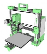
OneZ i3

Discussion in '3D printers' started by Keith Davis, Apr 17, 2016.

  1. TechGirl

    TechGirl New
    Builder

    Joined:
    Jun 26, 2015
    Messages:
    27
    Likes Received:
    5
    Here's a little something I knocked up for those of us without all the workshop tools. It's a little drill guide for drilling the mounting hole in the verticle 2020 extrusion.

    It is mounted to the 2020 extrusion with a M5x10mm bolt and an Openbuilds Speed Nut.

    Just align it as shown in the photo.

    This thing was made with Tinkercad.

    The STL file is also available at OneZ-i3 Drill Guide by TechGirl_Mods

    OneZ-i3_Drill_Guide.jpg
     

    Attached Files:

    #31 TechGirl, May 5, 2016
    Last edited: May 5, 2016
    Mark Carew likes this.
  2. Mark Carew

    Mark Carew OpenBuilds Team
    Staff Member Moderator Builder Resident Builder

    Joined:
    Jun 28, 2013
    Messages:
    2,759
    Likes Received:
    2,438
    Very nice and handy to have, thank you! :thumbsup:
     
    TechGirl likes this.
  3. TechGirl

    TechGirl New
    Builder

    Joined:
    Jun 26, 2015
    Messages:
    27
    Likes Received:
    5
    That's what I thought, especially as I don't have a big workshop.
     
    Mark Carew likes this.
  4. Keith Davis

    Keith Davis Veteran
    Builder

    Joined:
    Dec 11, 2013
    Messages:
    507
    Likes Received:
    398
    I just had a feeling you were going to have mods..... :thumbsup:

    BTW, I like your My Customized generic fan guard / filter / mesh / bee's nest by TechGirl_Mods fan guards. Think I'll use them, 30mm & 40mm - printing them now

    Suggestion: in your description at thingiverse of the drill guide, add a link to your comment here for people who find it by other routes. The url to that comment is OneZ i3 | Page 2 | OpenBuilds
     
    #34 Keith Davis, May 5, 2016
    Last edited: May 5, 2016
    TechGirl likes this.
  5. TechGirl

    TechGirl New
    Builder

    Joined:
    Jun 26, 2015
    Messages:
    27
    Likes Received:
    5
    As some other 2020 mounting plates for The Toranado Precision Geared 1.75mm Extruder (The Toranado Precision Geared 1.75mm Extruder - v1.1 by Toranado3D) licencing do not allow any derivatives and do not use Mini V Wheels, I decided to make my own.

    RepRap is about making self-replicating machines, and making them freely available for the benefit of everyone.

    I don't design things for this hobby of mine to make money, so, if anyone decides to change anything, all I ask is that you give me a shout out.

    This is a mix of the Openbuilds Mini V Gantry Plate (Mini V Gantry Plate™) and the OneZ-i3 X belt anchor bracket.

    I only use design tools that are freely available on the internet, mostly because I can't afford to do anything else. This thing was designed with Tinkercad and Sketchup. Edit it online 3D design TPGE-Mount-for-OneZ-i3
     

    Attached Files:

    #35 TechGirl, May 7, 2016
    Last edited: May 7, 2016
  6. Keith Davis

    Keith Davis Veteran
    Builder

    Joined:
    Dec 11, 2013
    Messages:
    507
    Likes Received:
    398
    Cool! I have a suggestion. As oriented in the stl, the recesses for the M5 screw heads are down, I'd flip them up for printing. Printed downward there will be bridging problems going from the recess size to the hole size. For adjusting the wheels mounted to an extrusion it is critical that the screws be perpendicular to the plate face and that bridging will not leave you a flat recess for the screw head if printed with those recesses downward. That said, that puts the recesses for the M4 screws on the down side where they will now have the bridging problem. So, here's a handy bridge eliminating trick I use for printing recesses on holes when recesses are down - put a 45 degree bevel on the hole inside of the recess. In this case, a 0.6mm offset in Sketchup's Rounded Corners plugin.

    [​IMG]

    An alternative here is to use the Openbuilds mini-wheel plate, thus guaranteeing proper tensioning of the wheels in the v-slot. The Toranado's mount holes are 4mm spaced 23mm apart. On the Openbuilds plate there are 4 M5 tapped holes. Drill out the two horizontal tapped holes to 6.5mm hole. That will make those holes large enough so you can then use the M4 screws through those holes to screw right into the Toranado's two bottom mounting holes (M4 screw button heads are 7.5mm). Two mount screw should be plenty strong enough, I use only two on my extruder body piece for mounting to the Openbuilds plate.
     
    TechGirl likes this.
  7. TechGirl

    TechGirl New
    Builder

    Joined:
    Jun 26, 2015
    Messages:
    27
    Likes Received:
    5
    You can just print the build plate without support in the orientation shown. There is a 0.2mm layer at the boundary between the different diameters of the 5mm holes. The Toranado mounting holes are sized for m3 heat set inserts (100pcs M3*4mm H62 Brass Knurl Nuts DIY Accessories). The TPGE has to be mounted using M3 dome headed screws to avoid binding on the 2020 rail.
     
    Keith Davis likes this.
  8. seve030608

    Builder

    Joined:
    Mar 22, 2016
    Messages:
    4
    Likes Received:
    11
    Just began the frame work for mine (had ALOT of help from Keith)! Could take me a min to get it up and running (it's my first)... IMG_20160507_164916180.jpg
     
    Steve Jeppesen likes this.
  9. Keith Davis

    Keith Davis Veteran
    Builder

    Joined:
    Dec 11, 2013
    Messages:
    507
    Likes Received:
    398
    It works both ways. I haven't responded to the suggestions you've emailed me, but they are going into the re-write of the Assembly Instructions (which I'm hacking away at now). The next Kit assembler is going to have an easier time because you're help, "Customer 0".

    BTW, those 45 degree brackets are indeed sloppy. But I think they are generic off-the-shelf as every T Slot extruder manufacturer offers the same bracket. On the Onez their purpose is to guarantee the 90 degrees of the two uprights. Actual strength (so you don't end up holding the handle and top bar with the rest of the printer bouncing off the floor) is accomplished by the corner top bracket which screws into upright and bolts to the top bar.
     
  10. Keith Davis

    Keith Davis Veteran
    Builder

    Joined:
    Dec 11, 2013
    Messages:
    507
    Likes Received:
    398
    Oh.... I was thinking they were M4 screws, not M3. As Rosanna Rosanna Danna used to say, "Nevermind".
     
  11. TechGirl

    TechGirl New
    Builder

    Joined:
    Jun 26, 2015
    Messages:
    27
    Likes Received:
    5
    I've just printed a test piece to show the mounting holes and the bridging layer in the M5 holes. tpge-mount-for-onez-i3.jpg
     
  12. Steve Jeppesen

    Builder

    Joined:
    Jan 21, 2016
    Messages:
    18
    Likes Received:
    1
    say, not sure this is the correct thread/post to do it in, perhaps create your own build log (somehow) - but I would enjoy following along with your progress of assembling your printer if you feel up to the task of posting your progress.
     
  13. Subramaniam S S

    Builder

    Joined:
    Apr 26, 2016
    Messages:
    16
    Likes Received:
    1
    [QUOTE="@Keith Davis, As you said there is no reason why you can't extend to 1000X1000X1000".[/QUOTE]

    After that, before buying all the components I started working on redesigning the whole printer. I have completed my design for 800X800X800 and did A LOT OF MODIFICATION, My friend said he would help in ANSIS analysis and Solidworks before making the printer.Also for heated bed i planned to use Acrylic sheet(bottom) and Glass(top), the glass will be heated using Nickel Chromium 25 AWG wire.

    So before i get into work, wanted to ask whether this design is possible,will there be any constrains ?

    I have slow internet i ll upload the whole SKP as soon as possible.
    assembly_test.jpg
    assembly_test.jpg assembly_test 2.jpg assembly_test 3.jpg assembly_test 4.jpg assembly_test 5.jpg
    Heated Bead will be similar to this.
    Capture_2.JPG
     
    #43 Subramaniam S S, May 12, 2016
    Last edited: May 12, 2016
    Keith Davis likes this.
  14. TechGirl

    TechGirl New
    Builder

    Joined:
    Jun 26, 2015
    Messages:
    27
    Likes Received:
    5
    When I tried to actually mount the Toranado I found that the mounting holes were slightly misaligned. So I have updated the STL to more accurately match the Toranado.


    Mounted_01.jpg Mounted_02.jpg Mounted_03.jpg Mounted_04.jpg Mounted_05.jpg
     

    Attached Files:

  15. Keith Davis

    Keith Davis Veteran
    Builder

    Joined:
    Dec 11, 2013
    Messages:
    507
    Likes Received:
    398
    Here's my suggestions. First of all, on the top corners, set them up as usual with the 45 degree brackets to ensure a 90 degree angle at both corners, then reinforce that using 90 degree plates on the back sides. At 800mm high it's going to need that reinforcement as you move it around.

    As for the Y axis, with a print that could go up to 800 high and 400 off from center, that would put a lot of stress on the Y axis wheels if you stick with just a 20x40 for the Y axis frame piece. You might get by with just graduating up to using a 20x80 (the universal build plate has holes for that if you want to use it for a wheel base to bolt to your acrylic build plate).

    But I think I'd go with two 20x40s separated out. If you use a 20x40 for your back extension, you could route the belt back beyond the 20x40 y frame and run the belt up the middle. I would also run that back extension piece all the way across so you can place the two rear feet at those two corners. Remember, you only want a 3 feet triangle to prevent wobble

    To mount the bar(s) going back to the rear extension, I'd mount them on the side of the 20x80 frame and drill holes in them to bolt on the same way the two uprights are bolted. Just some added stability.

    I see you already realized two handles will be better than one :thumbsup:

    [​IMG]

    [​IMG]
    [​IMG]
    [​IMG]
     
  16. Keith Davis

    Keith Davis Veteran
    Builder

    Joined:
    Dec 11, 2013
    Messages:
    507
    Likes Received:
    398
    Looks good. Thanks for the update. When you get the extruder all put together, could you weigh it, including your plate and wheels, nozzle, core (everything but the wiring). I'd like to compare what you have by weight.
     
  17. Subramaniam S S

    Builder

    Joined:
    Apr 26, 2016
    Messages:
    16
    Likes Received:
    1
    Yeah sure,

    And here is my assembly skp.

    i ll rework the design based on your suggestion.

    Also is it ok if i use smooth idler wheel instead flanged bearings.

    To prevent two rods(smooth and threaded) from moving downwards instead of placing a solid block(as per in the assembly), i have sealed the z axis rod mount(bottom pieces).

    Do you have any suggestion or idea for making a closed loop GT2 timing belt ?

    do you have any CAD for remote bowden feeder ?
     

    Attached Files:

  18. TechGirl

    TechGirl New
    Builder

    Joined:
    Jun 26, 2015
    Messages:
    27
    Likes Received:
    5
    I know that the overall weight of the Torenado (including the E3D, fans and NEMA14 motor) is 13-14oz, my mounting plate (including all the wheels etc.) weighed in at 2.3oz. I compared this to the Nema17 motor I was going to use which weighed in at 10.4oz on it's own.
     
  19. Subramaniam S S

    Builder

    Joined:
    Apr 26, 2016
    Messages:
    16
    Likes Received:
    1
    Thanks for the suggestion.

    Increasing the Z-Axis V-slot from 20X20 to 20X40 will provide more rigidity at the top right ? will it be enough ?

    Or should i provide any other additional support ?
     
  20. Steve Jeppesen

    Builder

    Joined:
    Jan 21, 2016
    Messages:
    18
    Likes Received:
    1
    Throwing this out there but without experience to say one way or another, but would adding a 2nd plate in front like Keith suggested on those upper corners help at all? Perhaps those plates Keith suggested on the rear side might be enough to prevent the sway - but I couldn't state that positively.
     
  21. Keith Davis

    Keith Davis Veteran
    Builder

    Joined:
    Dec 11, 2013
    Messages:
    507
    Likes Received:
    398
    My extruder assembled, with Nema 17 56 oz/in 40mm motor, E3D, E3D fan, spring, bearing, mount screws & Openbuilds mini-wheel kit weighs right at 16oz. With print cooling fan 17.6.
     
  22. Keith Davis

    Keith Davis Veteran
    Builder

    Joined:
    Dec 11, 2013
    Messages:
    507
    Likes Received:
    398
    @JustinTime is missing the bolt-in-slot at the bottom of the Z-Axis V-slot rail. Use a drop-in-tee-nut on that bolt (for better threads than a slide nut) and you can tighten that bolt down through the hole with a cheater bar on your hex wrench. If you go to 20x40 (which I recommend just for flex in the 20x20) and use a bolt-in-slot in each v-slot your joint there would be almost weld strong.

    At the top corner, adding a 90 degree plate should be sufficient. But, there is an easy way to make it so rigid you can use the printer as a step ladder. Like down at the bottom of the Z-Axis V-slot rail, drill an access hole 10mm from the top 90 degrees from the one at the bottom. Then tap thread the end holess of the top rail. screw a M5x10mm into that end, slide the Z-Axis V-slot rail slot over the head of that bolt, reach in through the access hole and cinch it down. The only way that corner could flex is if you break the bolt. Or, add a openbuilds endcap to the bolt and extend the bolt to the outside. That joint isn't going break unless you rip the extrusion apart or break the bolt. Imagine doing that with a 20x40 upright bolted that way to a 20x40 top rail.

    [​IMG]

    Don't even think of joining a open end belt into a closed loop. You'll lose a week trying it :banghead:. A good China source for closed loop belts on AliExpress is POWGE.

    Yes, use smooth idler wheel instead flanged bearings. I use flanged bearing just to reduce costs.

    The way I actually do the smooth linear rods is: drill out the top piece hole to 8mm to 20mm deep. Tap that to seat on a rod. Chuck the rod end into a pipe vise and wiggle the top piece back off of it (that makes it an easy press fit for later on). Then tap the rod down into the bottom piece to flush with the bottom of the hole. Then bolt the bottom piece to the printer. Later when the X axis has been positioned over the rods, you can easily tap the top pieces onto the rods and bolt them on. A main consideration - the X axis screws get acorn nuts fitted to their top. So the top of the screw's threads have be clean. Considering that you're going to cut those screws to correct length, the threads at the other end are not going to be clean. Here's what is important, you need to thread clean threads through the nylon nut on the X axis so as not to mess up the threads in the nut. So, I bring the threaded rod in from the bottom through that hole in the bottom bracket - clean threads up, thread it through the nylon nut, add the belt, pulley, washer and bearing, and keep threading it up through the hole in the top piece, add the bearing, washer and acorn nut.

    Do NOT rely on a blind hole in the bottom bracket to hold the Z screw up. The Z screw is anchored at the top. The acorn nut presses down on the top bearing, the pulley presses up on the bottom bearing, captivating the screw in the top bracket. The X axis therefore "hangs" from the top.

    A Bowden motor mount/driver is included in the http://3dwrx.com/openbuilds/i3/i300-assembly-parts.zip along with a Chimera mount.
     
  23. Keith Davis

    Keith Davis Veteran
    Builder

    Joined:
    Dec 11, 2013
    Messages:
    507
    Likes Received:
    398
    Read response to @Subramaniam S S above on that corner.

    You remember we talked about using a aluminum square bar for your trailer frame and covering it with a printed sleeve? Well, consider Openbuild's 40x40 extrusion instead

    [​IMG]

    You could bolt printed panels to it, or just use Openbuilds slot panels
    [​IMG]

    which I think would look cool!. The extrusion would provide v-slots for mounting U joint.
     
  24. Subramaniam S S

    Builder

    Joined:
    Apr 26, 2016
    Messages:
    16
    Likes Received:
    1
    I have completed the modification.

    Any suggestion from anyone ?

    assembly_1.jpg assembly_2.jpg assembly_3.jpg assembly_4.jpg assembly_5.jpg

    Can i use the "tpge-mount-for-onez-i3.stl" for Toranado extruder mounting ? is it working ?
     

    Attached Files:

  25. Keith Davis

    Keith Davis Veteran
    Builder

    Joined:
    Dec 11, 2013
    Messages:
    507
    Likes Received:
    398
    @Subramaniam S S Looks good. I'm having trouble extracting the assembly.zip - seems to be an error in the zip.

    Other than that, I like the extensions on the back for added strength. But, you also need a top bar connecting those two back corners. If not when you pick it up by the two handles they'll want to collapse towards each other, skewing everything else out of true.
     
  26. Subramaniam S S

    Builder

    Joined:
    Apr 26, 2016
    Messages:
    16
    Likes Received:
    1
    thank you for the suggestion, i ll add the bar at the top.

    And what about the Toranado extruder mounting ? do you have any idea ?
     

    Attached Files:

  27. Keith Davis

    Keith Davis Veteran
    Builder

    Joined:
    Dec 11, 2013
    Messages:
    507
    Likes Received:
    398
    That is @TechGirl 's mount. It looks good to me as far as fit. If a Toranado is what you want, I'd use it. She and I compared weights for my extruder w/Nema17 and hers w/Nema14 plus the weight of the gears and extra plastic and we were less than 1 oz difference. I run my extruder at 1/8 microstep so it has plenty of power and runs cool.
     
  28. Steve Jeppesen

    Builder

    Joined:
    Jan 21, 2016
    Messages:
    18
    Likes Received:
    1
    Thanks Keith for the 40x40 extrusion suggestion. I'll add that to the list of possibilities for the frame backbone.

    Here's a suggestion I sent to Keith last week regarding an alternate cooling fan shroud. He took the design and modified it just a bit so now the print cooling fan assy is just three pieces counting the fan itself.

    I've attached the .stl and .skp files. This has been confirmed to work on a OneZ Whisper i3, I have no idea if it would work on earlier versions however.

    Keith reported there were a couple of cracks that leaked air in the shroud and increasing perimeters to 150% irc solved that. I had printed my 1st set at 0.1mm layer height and it came out as air tight as possible but I'll be reprinting it at some point due to excessive blobs on the outside and inside surfaces - still fine tuning some profiles in Simplify3D.

    The assy would require (4) M3 x 30mm long screws. Both parts are printed upside down.

    Order of parts would be the "fan mount" (part on the left below), then the 40x40 fan and finally the fan shroud. I have not assembled what I've printed yet but it appears you may need to drill out the holes slightly.

    I may redesign the fan mount so that it includes TechGirl's fan cover pattern or possibly a custom one-off...had and idea overnight where I would print the text "OneZ Whisper i3" somehow within the confines of the air inlet and use that as a cover...not sure how that will come out though.

    I'm currently setup to print nylon - so the print cooling fan assy/upgrade isn't as important at the moment or I'd have pictures of this setup already!

    edit:

    updated model includes shroud wall thickness increase from 1mm to 1.5mm, shroud outlet slot increased to 8mm wide, holes in fan mount increased to 4mm so as no drilling required afterwards and the holes on the shroud were increased to 3mm.

    I've printed a set in nylon and I'm able to thread or twist a 3mm screw into the fan shroud but I'm not sure you'd be able to do that with PLA or ABS, might need to tap first.

    I was able to print this set with 0.2mm layer height but used 5 perimeters everywhere and 100% infill so there's no air leaks. You could probably get by with increased perimeters and it will be air tight.

    There's only an .stl file now. let me know if another file type is desired.

    upload_2016-5-29_4-22-54.png

    View attachment 16093
     

    Attached Files:

    #58 Steve Jeppesen, May 23, 2016
    Last edited: May 29, 2016
  29. Steve Jeppesen

    Builder

    Joined:
    Jan 21, 2016
    Messages:
    18
    Likes Received:
    1
    upload_2016-5-29_6-56-10.png

    working on a 30% infill print now, see if I can reduce or eliminate the warping (upper left corner of fan mount, you can see where that one warped)

    https://goo.gl/photos/3wVdum9Ueaai67bm7

    and no, it's not even plugged in so it's not in use LOL
     
  30. lihp8270

    lihp8270 New
    Builder

    Joined:
    Jun 11, 2016
    Messages:
    7
    Likes Received:
    0
    Hi,

    I have been looking for a 3D printer to build, since those I have access to aren't great. I love your idea of the one z axis motor, and will be following your design to build mine.

    I have acquired several Nema 17 1.8degree (200) motors. And noticed you have a firmware download for 200 step motors, OR, 400 step on the X&Y. Does this mean the whole build can be done entirely with 200 step motors? If so, what is the advantage to using the 400 (0.9deg) step motors on the X & Y axis?

    Thanks
     

Share This Page

  1. This site uses cookies to help personalise content, tailor your experience and to keep you logged in if you register.
    By continuing to use this site, you are consenting to our use of cookies.
    Dismiss Notice