Welcome to Our Community

Some features disabled for guests. Register Today.

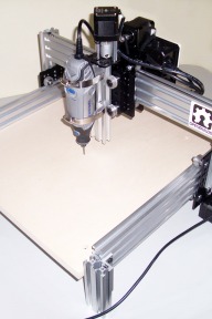
Routy GT2 290 BSX CNC Router, Low Cost and Good!

Discussion in 'CNC Mills/Routers' started by Ronald van Arkel, Aug 4, 2015.

  1. Ronald van Arkel

    Staff Member Builder Resident Builder

    Joined:
    May 7, 2014
    Messages:
    472
    Likes Received:
    245
    @ensari cokur,

    Starting to look great ;). Just set the gantry height to the height you need, this will reduce flexing of the X/Z axis.

    Next design might be based on stock V-Slot lengths. It seems that most people don't want to cut.

    Thank you for posting!

    -Ronald
     
    #61 Ronald van Arkel, May 20, 2016
    Last edited: May 20, 2016
  2. ensari cokur

    Builder

    Joined:
    May 5, 2016
    Messages:
    29
    Likes Received:
    6
    Thank you. Yes after cutting v-slots I need to face it to make it perfectly square. I don't have a cnc mill. That's why keeping v-slot's as it is, makes the job a lot easier. Makes the machine more precise.
     
  3. David Crain

    Builder

    Joined:
    May 17, 2016
    Messages:
    17
    Likes Received:
    3
    Hey Ronald,

    Was wondering what's your recommended maximum size for the routy 290? Would 18" x 24" x 6" be too much? I just got my v-rails in today and I'm still contemplating how big I want this to be before I start cutting.... Thanks! Looking forward to your reply. Btw.. I didn't get enough v-rail to add support beams across the bottom.
     
  4. Ronald van Arkel

    Staff Member Builder Resident Builder

    Joined:
    May 7, 2014
    Messages:
    472
    Likes Received:
    245
    Hello David,


    The Y and X size will not be a problem, but you need to tinker a bit with the Z-axis to have a work height of 6". The Routy was made to do 2 to 3" So you might need to double up the X axis like on the Ox in the near future. This isn't that hard and expensive to do so don't worry about that for now. Did you get the extra NEMA17 Acme rod plate (with bearing and lock collar) for the Z axis? Anyway, everything is adjustable, just build it like you want it for now; you can lower the gantry easily if needed.


    You might be able to use wood to make the support beams of the table, might be sturdier as well.


    -Ronald
     
  5. David Crain

    Builder

    Joined:
    May 17, 2016
    Messages:
    17
    Likes Received:
    3
    Hey Ronald,

    Thanks for getting back. I basically want the ability to 3d print with the routy as well. I did get the extra acme rod plate and bearing and lock collar as you mentioned before. I'll take a look at the Ox and see what you mean about doubling up. Sounds like maybe adding an extra v-slot for extra support?
     
  6. Ronald van Arkel

    Staff Member Builder Resident Builder

    Joined:
    May 7, 2014
    Messages:
    472
    Likes Received:
    245
    This is why I said, build like you think it will work, there are always ways to make the Routy work for your needs without rebuilding the whole machine ;). Doubling up the X axis you could see here: Routy GT2 290 BSX CNC Router, Low Cost and Good!
     
  7. David Crain

    Builder

    Joined:
    May 17, 2016
    Messages:
    17
    Likes Received:
    3
    I gotcha... basically adding another v-slot and v-wheels for extra rigidity.... thanks again for your suggestions.. guess i'll build it how i originally speced it out for now and go from there.....
     
  8. Ronald van Arkel

    Staff Member Builder Resident Builder

    Joined:
    May 7, 2014
    Messages:
    472
    Likes Received:
    245
    You can't go wrong unless you cut the V-Slot to short, still V-Slot isn't the expensive part of the Routy, and it’s mostly the other hardware that makes the price. Don’t we love OpenBuilds? ;).
     
  9. David Crain

    Builder

    Joined:
    May 17, 2016
    Messages:
    17
    Likes Received:
    3
    Hey there Ensari,

    I see you're setting up a routy 290 as well. What is your build volume looking like? Have any idea what your z axis travel will be?

     
  10. ensari cokur

    Builder

    Joined:
    May 5, 2016
    Messages:
    29
    Likes Received:
    6
    Z axis travel is easily adjustable. Right now I have 4-5 inches. I don't know about the rigidity for now. Still building. I work for a CNC company, asked to use their machines to face(mill) the ends of the v-slots. V slots that we get, are not perfectly same size that makes the table out of square. I would suggest you the same. For X and Y i didn't shorten the v slots. Made same changes from the original design. This gave more travel on X and Y. Z needs more support. I will share pictures soon. I m using some precision tools to make the router as square as possible. Will be good to share the experiences while building :)
     
  11. David Crain

    Builder

    Joined:
    May 17, 2016
    Messages:
    17
    Likes Received:
    3
    Thanks for your reply! Looking forward to seeing more on your build.

     
  12. David Crain

    Builder

    Joined:
    May 17, 2016
    Messages:
    17
    Likes Received:
    3
    Hey Ronald,

    One more question and I'll quit bugging you.. :) These are my proposed dimensions for my routy 290 build. Do you see any problems with the following cuts? I basically just worked off your measurements and added/subtracted the proper lengths:

    460mm x 610mm x 150mm (workable area) 18"x24"x6"

    Actual v-slot cut

    X - 603mm
    Y - 790mm
    Z - 312mm (lead screw - 300mm)

    Table Support cut

    591mm

    X axis support

    602mm

    Y axis sides

    312mm

    Legs

    140mm?? Will the extra 20mm make them flush with with Y axis rails?
     
  13. Ronald van Arkel

    Staff Member Builder Resident Builder

    Joined:
    May 7, 2014
    Messages:
    472
    Likes Received:
    245
    @David Crain

    Have faith in yourself ;). It looks you are worried too much on cutter the V-Slot. As far as I can see all numbers look okay although the Acme screws come in 290mm lengths, note that with the extra Acme rod plate you need the extra length.

    I made the legs 140mm and not 160mm due to not having enough material left and if a black angle corner needed could be used to cover botch V-Slot off. To keep the build as in-expensive as possible I left the corners out.

    @ensari cokur, looking forward to see how it will turn out. I use a miter saw and lubricant to cut the V-Slot to 0.5mm precise.

    -Ronald
     
  14. ensari cokur

    Builder

    Joined:
    May 5, 2016
    Messages:
    29
    Likes Received:
    6
    I have a miter saw but for wood? Would it cut? Or yours for metal?
     
  15. Ronald van Arkel

    Staff Member Builder Resident Builder

    Joined:
    May 7, 2014
    Messages:
    472
    Likes Received:
    245
  16. ensari cokur

    Builder

    Joined:
    May 5, 2016
    Messages:
    29
    Likes Received:
    6
    You have a nice miter saw with adjustable speed. Mine is single speed and 3500rpm. I think it's too much for aluminum. I will buy one like yours. Thanks
     
  17. Ronald van Arkel

    Staff Member Builder Resident Builder

    Joined:
    May 7, 2014
    Messages:
    472
    Likes Received:
    245
    Mine is still single speed as well, no laser and all that. I use WD40 for cutting/cooling but there is special cutting grease that I can't seem to find locally and import is close to impossible.
     
  18. David Crain

    Builder

    Joined:
    May 17, 2016
    Messages:
    17
    Likes Received:
    3
    Hey everyone.. I made a bone head move.. I'm assembling the x-treme solid v-wheels and didn't realize one of the washers had to go inside of one of the bearings in the wheel. I just snapped the bearings in both sides and thought all was well. Don't really see an easy way to remove the bearings and insert the washer. Should I be ok? I did this to four of them on the z axis gantry plate. Thanks!
     
  19. Rick 2.0

    Rick 2.0 OpenBuilds Team
    Staff Member Moderator Builder Resident Builder

    Joined:
    Dec 20, 2013
    Messages:
    2,892
    Likes Received:
    1,551
    No, you won't be okay. As soon as you tighten the wheels properly your wheels will seize up and potentially do damage to the bearings. Best suggestion is to take a heavy duty paper clip, straighten it out, bend it back in half and bend a small hook on each end to where you slip those hooks in between the bearings to pull out a bearing. Pushing out the one on the far side may also work.
     
  20. David Crain

    Builder

    Joined:
    May 17, 2016
    Messages:
    17
    Likes Received:
    3
    thanks! yeah... after an hour i finally got the one side off.... dang that was tough.. lol thank god i didn't do all 16 like that!!!
     
  21. David Crain

    Builder

    Joined:
    May 17, 2016
    Messages:
    17
    Likes Received:
    3
    Just wanted to share my progress with my build. So far so good. Build envelope is 18"x24"x6".
     

    Attached Files:

    Ronald van Arkel likes this.
  22. David Crain

    Builder

    Joined:
    May 17, 2016
    Messages:
    17
    Likes Received:
    3
    dang it.. just noticed I mounted the L brackets the wrong way on the x axis.. oh well... i'll fix it tomorrow.
     
  23. ensari cokur

    Builder

    Joined:
    May 5, 2016
    Messages:
    29
    Likes Received:
    6
    Your z axis looks very long. I think you may have rigidity problems. but its easy to fix, if you dont like it :)
     
  24. David Crain

    Builder

    Joined:
    May 17, 2016
    Messages:
    17
    Likes Received:
    3
    Yeah im going to do some testing and see how it performs at its current height. I hope it works as i want to 3d print with it too.
     
  25. David Crain

    Builder

    Joined:
    May 17, 2016
    Messages:
    17
    Likes Received:
    3
    Good call! Didn't even take that into account. Guess I'll have to come up with an easy way to mount and dis mount this thing.. Although it's not really bad as it is......

     
  26. ensari cokur

    Builder

    Joined:
    May 5, 2016
    Messages:
    29
    Likes Received:
    6
    Hi,

    Arduino Uno, even a clone can be used, needs to be flashed with GRBL
    • Set for X and y axis speed to 5000mm/min and 50 on aceleration, steps per mm at 57.14 (make sure your shield is set at 1/8 step)
    • Set for Z axis speed to 2000mm/min and 50 on aceleration, steps per mm at 200 (make sure your shield is set at 1/8 step)
    I adjusted the steps per mm 57.14 for x and y, 200 for z. But I couldnt find x y z axis speed. And acceleration is common for all axes. I m using universal g code sender. How can I do that?
    Thanks
     
  27. Ronald van Arkel

    Staff Member Builder Resident Builder

    Joined:
    May 7, 2014
    Messages:
    472
    Likes Received:
    245
    Hello @ensari cokur,

    The "speed" you are talking about is called "feed", used for example in G-code G00 or G01 Y30 F2500 (you guessed it, "F" stands for feed).

    Now, the above is manual movement; a G-code generator/CAM will ask you more parameters like bit-size, material to cut and more. Look at ESTLCAM, free to try, small fee to buy; best CAM I've found so far for the hobbyist (or even profesional) ;).

    -Ronald

    Edit; removed some text, all Arduino Uno´s I've seen are 16MHz.
     
    #87 Ronald van Arkel, Jun 5, 2016
    Last edited: Jun 6, 2016
    GrayUK likes this.
  28. ensari cokur

    Builder

    Joined:
    May 5, 2016
    Messages:
    29
    Likes Received:
    6
    Thank You for all your help Ronald.
    I finally finished. Now I will start developing that. I have almost 390mm(14.8"), Y travel and 350mm(13") X travel and 4" Z cutting height.

    Here is the video;
     
    Ronald van Arkel likes this.
  29. Ronald van Arkel

    Staff Member Builder Resident Builder

    Joined:
    May 7, 2014
    Messages:
    472
    Likes Received:
    245
    @ensari cokur,

    That's sweet! Thank you for posting the video. Make sure your table is 100% straight with the Dremel 3000 you are using.

    Even for the larger machines I use the Arduino Uno:

    IMG_00884.JPG

    Make sure you give ESTLCAM a try!

    -Ronald
     
  30. ensari cokur

    Builder

    Joined:
    May 5, 2016
    Messages:
    29
    Likes Received:
    6
    First cut. Spindle and table perpendicular:)
     

Share This Page

  1. This site uses cookies to help personalise content, tailor your experience and to keep you logged in if you register.
    By continuing to use this site, you are consenting to our use of cookies.
    Dismiss Notice