Welcome to Our Community

Some features disabled for guests. Register Today.

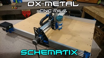
OX-Metal CNC Router Mill

Discussion in 'CNC Mills/Routers' started by Schematix, Jul 6, 2016.

  1. Andrespmi70

    Builder

    Joined:
    Dec 13, 2016
    Messages:
    5
    Likes Received:
    0
    It's been a long time since I want to build a CNC machine and this one looks great and the size is perfect. I think I am going to build it. I have a few concerns, where can I get the 3D printed parts?, and its possible using the table and motors to convert to a 3D printer the CNC itself? I mean is it possible to use the table for both things? Maybe making an inset in the middle that can go down below table level to build the 3D parts, if you need more clearance from the horizontal beam.
    Thanks so much
     
  2. SugarJ

    SugarJ Well-Known
    Builder

    Joined:
    Nov 16, 2015
    Messages:
    126
    Likes Received:
    47
    You can make the parts yourself if you have a 3D printer. Or you can use a local 3D printing company (I use 3Dhubs.com to find them). Or in the comments page on Thingiverse there's a link to someone offering them for sale.

    I can't see why you couldn't make an adapter to put a hot-end and extruder on the Z-axis piece. However you'd be a bit limited in height travel compared to what most 3D printers offer, and it might not be worth the effort as you can find 3D printer kits for less than $250 from Aliexpress. There would also be an issue if you want to include a heated bed somehow.

    Another cool option would be to add a laser for etching glass or acrylic.

    BTW, I'm not affiliated with Schematix or anyone else. I'm in the process building one of these myself. All the parts are in my shop, just waiting for my 3D printer to finish making parts. :)
     
    crazerico likes this.
  3. Andrespmi70

    Builder

    Joined:
    Dec 13, 2016
    Messages:
    5
    Likes Received:
    0
    Ok in the country I am living now, I can not find the parts so I would have to order them online. One stupid question, if I send the file to these guys from 3dhubs.com they will know what to print?
    I have downloaded the file and for me it's not very clear, one thing I am doubting is about the 4-6 mm parts. Can you tell me how are you printing yours? type of plastic and all details? I will tell the guys from 3dhubs.com
    I want to have only one table at home, that's the reason for my question.
    Thanks very much.
     
  4. SugarJ

    SugarJ Well-Known
    Builder

    Joined:
    Nov 16, 2015
    Messages:
    126
    Likes Received:
    47
    I'm printing mine in PLA, because that's what I have in the shop. ABS might be a better choice. I think you're better off getting your aluminum plates organized first, then picking either the 4mm thick plate parts or 6mm thick to print to match.

    I'm using 20% infill on the parts like the limit mounts that won't be stressed a lot, 50% infill on the Nema 23 and Leadscrew mounts. This might not be a heavy enough infill, I'm just guessing at what should work. I'm lucky in that I have my own printer and can remake the parts if they don't work.
     
    crazerico likes this.
  5. wdennis0456

    Builder

    Joined:
    Nov 5, 2016
    Messages:
    2
    Likes Received:
    0
    They are out on their site but its available for purchase on Amazon from Openbuilds. I ordered mine early November only took a few days to arrive
     
  6. Andrespmi70

    Builder

    Joined:
    Dec 13, 2016
    Messages:
    5
    Likes Received:
    0
    So i understand that the plates, aluminum ones are available in 4 or 6 mm and so the plastic parts are built according to the thickness of the plates.
     
  7. JP Warnke

    JP Warnke New
    Builder

    Joined:
    Jan 4, 2017
    Messages:
    32
    Likes Received:
    10
    A nice looking machine.

    Thinking about building this myself!

    Couple questions:

    Approx total cost of everything you used to build yours (including dust extractor and limit switches)?

    Any idea how smooth a finish you might get (how much chatter) on small scale hardwood 3d relief stuff?
     
  8. Eric Girard

    Builder

    Joined:
    Mar 12, 2016
    Messages:
    6
    Likes Received:
    1
    Hi,

    VERY nice machine. Would it be able to engrave mild-steel plates (about 1/16" width lines by 1/16" depth ?). My main use would be for wood and aluminium but I may gave small jobs for steel, I don't mind slow feed rate / multiple passes as long as I can do it.

    Cheers!
     
  9. Andrespmi70

    Builder

    Joined:
    Dec 13, 2016
    Messages:
    5
    Likes Received:
    0
    Hello in one place in New York, they ask me about 250$ for the 3D parts made in ABS. IS IT TOO EXPENSIVE?
    Thanks
     
  10. Eric Girard

    Builder

    Joined:
    Mar 12, 2016
    Messages:
    6
    Likes Received:
    1
    This is way too expensive for the parts. I have a 3D printer, send me a message if you're interested...
     
  11. kuharskej

    kuharskej New
    Builder

    Joined:
    Sep 25, 2016
    Messages:
    1
    Likes Received:
    0
    The build list calls for (13) Eccentric Spacers and contains a link to Eccentric Spacer but doesn't specify if they should be 6mm or 1/4 in. Any ideas?
     
  12. SugarJ

    SugarJ Well-Known
    Builder

    Joined:
    Nov 16, 2015
    Messages:
    126
    Likes Received:
    47
    They should be the same size as the spacers you use on the wheels that don't adjust. IIRC they are 6mm, but you should check the build video. I bought 1/4" eccentrics and got lucky in that my wheel kits came with 1/4" spacers.
     
    crazerico likes this.
  13. Rodm

    Rodm Well-Known
    Builder

    Joined:
    Jan 3, 2017
    Messages:
    121
    Likes Received:
    42
    I like this build to, had the same thoughts but want something a bit bigger. I went on looking at other builds not relying on 3design parts. After some more research I was impressed by what people are doing, designing and building with 3d printers. I looked into it a bit and ended up ordering an Anet a8 of eBay for $180. I'm not sure it will end up good enough for cnc parts but should do fine prototyping and there are a lot of fun other stuff to do withe it. I just finished the build this morning. Will be testing things out soon.
     
    #43 Rodm, Jan 29, 2017
    Last edited: Jan 30, 2017
  14. Rodm

    Rodm Well-Known
    Builder

    Joined:
    Jan 3, 2017
    Messages:
    121
    Likes Received:
    42
    I saw that video too. Luckily before I ordered. I was amazed how many listing used a 8 pictures, pictures of a8 flyers without a8 name, ect.... I clicked on the detail - specifications tab on at least a half dozen. About half didn't have anet listed as manufacturer or a8 as model. I could tell find a listing that did both. I ordered from one that had anet a8 in listing name, Anet listed as manufacturer and a decent seller rating. That said, did I get the Anet a8? I don't know. I think so. Box was unmarked but at least not another manufacturer name like in video. No literature in box. The little bags for hardware had a8 on them, SD card had anet a8 instruction and info and it looks like the a8. Hopefully whatever it is it prints well.
     
  15. swoehl

    swoehl New
    Builder

    Joined:
    Feb 7, 2017
    Messages:
    2
    Likes Received:
    0
    Great updates to the OX and nice build video. Bought all the parts to start the build, but only plates available are in 3mm stainless. How would the 3D printed parts need to be adjusted to account for the reduced width from 4mm to 3mm? Additionally, I'm wondering if you can have different Z axis shuttles with different types of tools - laser for cutting/etching would be my first and easiest option, but not sure if there are other required updates on the software side of things? Different controller, or additional controller for the different operations? Thoughts?

    Looking forward to having this in the shop!
     
  16. SugarJ

    SugarJ Well-Known
    Builder

    Joined:
    Nov 16, 2015
    Messages:
    126
    Likes Received:
    47
    I'm in the process of building mine, but I think the easiest option would be to add 1mm shims to the X carriage leadscrew mount and the Y leadscrew spacers next to the plates where the screws pass through. This would make up your 1mm of difference. This would add 8x 1mm shims to the build.

    Otherwise you could add 1mm of height to the Y leadscrew spacers, and narrow the outer channels of the X carriage by 1mm.

    You can mount any tool to the Z-axis (router, laser, 3-D printer hot-end), it's just a matter of making a mount for it. You'd have to program your software properly for the correct steps/mm per axis.
     
    crazerico likes this.
  17. swoehl

    swoehl New
    Builder

    Joined:
    Feb 7, 2017
    Messages:
    2
    Likes Received:
    0
    I made the outer flaps on both sides of the X Carriage Leadscrew Mount 1mm thicker on the inside face to account for the difference in plate thickness. I also made the Y leadscrew spacer 1mm wider by giving the base 1mm in height. I think that should cover the updates you mentioned.

    When I go to print the X carriage leadscrew mount it is auto positioned to have the short edge of each one of the flaps on the print bed. Is that the proper orientation to print? I tried to see the layer orientation from the video, but not able to get there. I'm assuming for stability, but can't work out which way it needs to be most stiff relative to the weak shearing force required to separate layers of print. Hope that last part makes sense. I'm printing in PLA because that is what I have around and want to make choices which do not further compromise the structural capability of the part over what my material choice has already done. I thought a pic of the orientation might help as well.

    upload_2017-2-11_21-16-14.png
    Thanks!
     
  18. SugarJ

    SugarJ Well-Known
    Builder

    Joined:
    Nov 16, 2015
    Messages:
    126
    Likes Received:
    47
    When I printed mine I rotated it so that the bottom of the carriage was the bottom of the print. I used PLA with 50% infill on structural items, 20% on the drag chain and limit switch mounts. I'm not in operation yet, this may not be enough.
     
    crazerico likes this.
  19. Andrespmi70

    Builder

    Joined:
    Dec 13, 2016
    Messages:
    5
    Likes Received:
    0
    Hello
    Yes I am interested, i will send you a message when I am starting to build this CNC machine. Thanks so much!
     
  20. crazerico

    crazerico New
    Builder

    Joined:
    Jan 26, 2017
    Messages:
    15
    Likes Received:
    5
    Hey thanks for your post.
    To someone new like me it pointed me in the right direction
    even thought my build is about 90% complete now im having to go back and change out some plates.
    so it does pay to read read and more reading before starting.
    i didn't do that so its costing me more $ i don't have.
     
    GrayUK likes this.
  21. GrayUK

    GrayUK Openbuilds Team Elder
    Staff Member Moderator Builder

    Joined:
    May 5, 2014
    Messages:
    1,668
    Likes Received:
    627
    Crazerico.
    You don't know how many times I've told people to read, read and then read some more, plus watch You Tube videos, until you get the positive feeling that you know what you're getting into. :banghead:
    It does take time, and patience, to know what path you want to go down, and not have it cost you extra cash for cutting back on the research.
    It is true there is an awful lot of information on this Forum, and it can get a bit boring reading about people making the same mistakes, but their problem can seriously save you from making the same one. :D
    Good luck, and may all your future mistakes be small cheap ones!! :thumbsup:
    Gray
     
    crazerico and Eric Girard like this.
  22. crazerico

    crazerico New
    Builder

    Joined:
    Jan 26, 2017
    Messages:
    15
    Likes Received:
    5
    i hope cheaper ones lol
     
  23. kotagi

    kotagi New
    Builder

    Joined:
    Jan 7, 2017
    Messages:
    3
    Likes Received:
    0
    Where did you mount the power supply? I got everything(waited forever because parts were on backorder from openbuilds) everything going smoothly until I tried to put the flex couplers on and they werent the right size. They were supposed to be 1/4 inch so now my build is on hold until I get those in. I didnt see any sizes on the parts list, it just says get the right size for your nema motor(which I didnt know the size so I guessed) Maybe I missed something but it would be helpful to post the sizes of parts that come in multiple sizes like that. Im sure someone will point out that I missed something, and that is totally possible. On the parts list I suggest putting sizes for the coupler and the eccentric spacers. Thank you for the build videos. I also noticed that some of the spots you call for a 15mm screws it just is barely too short, and I have to go with a 20mm screws. I dont think that it matters, but I figured I would throw that out there in case anyone else ran into that
     
  24. Giarc

    Giarc OpenBuilds Team
    Staff Member Moderator Builder Resident Builder

    Joined:
    Jan 24, 2015
    Messages:
    3,008
    Likes Received:
    1,676
    The motors list the shaft size in the product description. If I remember correctly, NEMA 17 are 5mm and NEMA 23 are 6.35 mm. As long as both your eccentric spacers are the same length as the corresponding aluminum spacer, either size will work. But don't use both 1/4 inch and 6 mm on the same plate. Personally, I would pick one length and stick with it for the whole build. I agree that could be clarified.
     
  25. kotagi

    kotagi New
    Builder

    Joined:
    Jan 7, 2017
    Messages:
    3
    Likes Received:
    0
    On the u-step jumper settings on the xpro, do I leave it a 8th microstepping, or is there another setting that is better. Feel free to school me im still learning everything. And thank you in advance!
     
  26. SugarJ

    SugarJ Well-Known
    Builder

    Joined:
    Nov 16, 2015
    Messages:
    126
    Likes Received:
    47
    You should put your power supply where it doesn't get shavings or dust in it. I mounted mine on the underside of my workbench top. My emergency stop is mounted on the front of the bench in easy reach.
     
  27. lucascorato

    Builder

    Joined:
    Feb 20, 2017
    Messages:
    10
    Likes Received:
    1
    I'm planning on using a 3hp, 24000 RPM air cooled spindle on it, but it weighs 5,8kg (12,8 lbs), would that be a problem?
     
  28. JamieMcC

    JamieMcC New
    Builder

    Joined:
    May 3, 2017
    Messages:
    9
    Likes Received:
    4
    Outstanding and inspiring build video thanks for sharing.

    After losing way to many hours online researching ready assembled cnc options finding the openbuilds community has been like a breath of fresh air. The amount of information across so many builds has been inspiring provided the confidence to consider a build from scratch.

    The Oz metal looks perfect for my requirements I note on the overview video the XYZ amount of travel is given. So for my very first newbie forum question (completely new to the cnc world).

    Is the XYZ travel amount given in the first video the same as *actual machine able XYZ working area* particularly the X axis which is given in the intro video as 610mm (my max machining requirement is 600mm x 600mm x 25mm) if so the OX Metal looks a perfect fit for my needs and I can start putting my shopping list together.

    Cheers

    Jamie
     
  29. SugarJ

    SugarJ Well-Known
    Builder

    Joined:
    Nov 16, 2015
    Messages:
    126
    Likes Received:
    47
    I keep forgetting to throw my tape measure on my machine to answer this for you. Basically it's the width of the machine frame minus 40mm for the Y-Rails and minus the width of the gantry plate. I'm thinking it's actually around 580 mm but will measure to confirm. It would be easy to make it wider, just add 100 mm to all 744mm and 750mm parts and order your v-slot accordingly.

    Unfortunately the original designer hasn't been around the site lately. You may want to check Kyo's Sphinx build and DazTheGas' custom Ox Mods for ideas, both are leadscrew driven as well. Custom Ox Mods
    C-Beam cnc
     
  30. JamieMcC

    JamieMcC New
    Builder

    Joined:
    May 3, 2017
    Messages:
    9
    Likes Received:
    4

    Thanks Sugar

    I was watching the OX metal grbl set up video and a different width dimension is given 600mm. Your 580mm matches up closely with those given for the ooznest ox cnc (570 x 775mm working area from a 750 x 1006mm chassis)

    Today I have taken a good look at and tentatively priced up a 1mx1m C-Beam option and will do the same for a Kyo's Sphinx build later this week.

    With both the C-Beam and Sphinx off the shelf parts are not a problem and I will also keep an eye out for the DazTheGaz Ox Mod plates becoming available in the UK (I’m UK based as well) This would actually be an easier route for me than going down the path of printing out the plastic parts of the Ox metal.

    Cheers
    Jamie
     

Share This Page

  1. This site uses cookies to help personalise content, tailor your experience and to keep you logged in if you register.
    By continuing to use this site, you are consenting to our use of cookies.
    Dismiss Notice