Welcome to Our Community

Some features disabled for guests. Register Today.

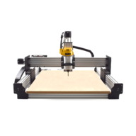
WorkBee CNC Machine

Discussion in 'CNC Mills/Routers' started by Ryan Lock, Sep 21, 2017.

  1. Metalguru

    Metalguru Veteran
    Builder

    Joined:
    Dec 29, 2015
    Messages:
    752
    Likes Received:
    547
    No problem. Perhaps it was as SugarJ said, it's so obvious to me.

    You could wire it up in the reverse direction as well, with +'s connected to Arduino and -'s to ground, but I didn't want to confuse the issue further.

    As SugarJ pointed out, you do need to set $2 to 7, and also you will likely need to set $4 to a 1 as well, since the Enable lines are active low. If any of your motors turn backwards, you can either reverse one of the motor phases (ie red and green), or use the $3 to invert the direction of the motors.

    Note: Do Not unplug the motors or power from the stepper drivers or change switch settings with the power on! You risk blowing the drivers if you do.

    MG
     
    John Mayer likes this.
  2. mheikki

    mheikki New
    Builder

    Joined:
    Apr 20, 2018
    Messages:
    1
    Likes Received:
    0
    Hi, I'm not sure if this is right place to pose a question on making holes wit ooznest (or any cnc), but still. Is there a recommended ratio between carbide end mill and hole diameter? For example should I use 10mm carbide end mill for a 10mm diameter hole, or is result better making it with 4mm carbide end mill?

    Heikki
     
  3. John Mayer

    Builder

    Joined:
    Aug 17, 2018
    Messages:
    24
    Likes Received:
    8
    After all your help I was finally able to wire the step drivers. I was trying to do a run test to make sure everything went well. I programmed the Arduino with GRBL, then tried to jag the motors individually. I tried both Uno and Nano, all axis motors work with the Uno, only the Y and Z axis work with the Nano for some reason. I have tried different Nano and different screwshiled with the same result. While
    X axis not physically turning it's showing that it's jogging fine within the software. Y and Z axis are working they only turning in one direction i.e clockwise or counterclockwise and when I reverse the wires the start turning only in the other direction.

    I have also tried to test the Estlcam program on both Uno and Nano using the 2 GRBL settings, GRBL 0.8 (traditional) and 0.9-1.1 (latest). I am not able to control any of the motors with Estlcam.

    Any thoughts on hints to put me in the right direction?

    Thanks in advance!
     
    #423 John Mayer, Sep 13, 2018
    Last edited: Sep 14, 2018
  4. Metalguru

    Metalguru Veteran
    Builder

    Joined:
    Dec 29, 2015
    Messages:
    752
    Likes Received:
    547
    John:

    Nor sure what the problem would be. There is no reason why it should not work with a Nano but does work with an Uno. Even the pinout is exactly the same. Unless you have 2 Nanos with the same fault?

    The only thing different is the configuration file on the board. Check to make sure all your settings are the same. The only other thing I could think of was an intermittent wiring fault, but that's pretty unlikely. Did you try swapping the X and Y axis or X and Z outputs to see if it works? Do you have a scope that you can check the output of the Arduino board with?

    I have never used the EstlCam controller firmware, so I have no idea about that. I would stick to using the GRBL 1.1f version for now, just in case it's something about the EstlCam firmware. EstlCam is a great CAM program, but I'm a bit leery about their controller software. GRBL is a pretty stable and well supported package, the EstlCam stuff is pretty much an unknown entity. If you paid for EstlCam, you could contact their tech support and see what they have to say.

    MG
     
    #424 Metalguru, Sep 14, 2018
    Last edited: Sep 14, 2018
  5. Giarc

    Giarc OpenBuilds Team
    Staff Member Moderator Builder Resident Builder

    Joined:
    Jan 24, 2015
    Messages:
    3,008
    Likes Received:
    1,676
    Did you program the Arduino board with the Estlcam controller? Or did you just try to use the Estlcam Controller? I use Estlcam and may be able to help.

    estl.png
     
  6. John Mayer

    Builder

    Joined:
    Aug 17, 2018
    Messages:
    24
    Likes Received:
    8
    I did program both Uno and Nano. The EstlCam recognized them as if they were programmed and show them when I try to tluse the controller, however it can't move any of the motors
     
  7. John Mayer

    Builder

    Joined:
    Aug 17, 2018
    Messages:
    24
    Likes Received:
    8
    Yes. I tried to swap it and it does work when I do. I have a scope and will check them tomorrow. I tested another Nano, with this one I can run all axis, however they turn in one direction only.
     
  8. Metalguru

    Metalguru Veteran
    Builder

    Joined:
    Dec 29, 2015
    Messages:
    752
    Likes Received:
    547
    That sounds like either a wiring error on the Direction outputs, or perhaps a configuration issue...

    MG
     
  9. John Mayer

    Builder

    Joined:
    Aug 17, 2018
    Messages:
    24
    Likes Received:
    8
    It could be the settings but I doubt it the wiring. The reason I say this because I can just swap the Nano without messing with any wire and still have different results. i.e one Nano run 2 axis and the other run all 3 axis in one direction. When using Uno with the same wiring I have all 3 axis working in both directions.

    Can you elaborate more on the "configuration" please?
    Thanks!
     
  10. Metalguru

    Metalguru Veteran
    Builder

    Joined:
    Dec 29, 2015
    Messages:
    752
    Likes Received:
    547
    Read this:

    gnea/grbl

    You may have the step pulse inverted, dir pulse inverted, or some other setting incorrect. Make sure all the settings for the Nano are exactly the same as for the Uno.

    There is no reason why a Nano should not work perfectly well in this application. I've used literally dozens of them, albeit not with the DM542 drivers. The fact that one board works and the other does not tells me that board is probably bad. Check to see that your 5V Nano supply is not being dragged down by the drivers causing unstable operation. Are you using the external power supply for the Uno?

    If all else fails, just give up and use the Uno and forget the Nano...

    MG
     
    Mark Carew likes this.
  11. John Mayer

    Builder

    Joined:
    Aug 17, 2018
    Messages:
    24
    Likes Received:
    8
    I have checked the Nanos with a scope and they seem fine. The nano settings are identical to the uno settings. I have order 10 additional Nanos to find out that none of them work properly. Out of the 10 there's only one that turns all three axis. Although it turns X axis in both directions it only turn Y, Z axis in one direction.

    On other note, I can't manage to get any voltage out of the Nano once it connected to the DM542 drive? Am I missing something here?

    To answer your question, no. I don't use an additional PS for the Uno. I just hook it to the PC using the USB.
    The nano can use GRBL (v9) 1.1, right?
     
  12. Metalguru

    Metalguru Veteran
    Builder

    Joined:
    Dec 29, 2015
    Messages:
    752
    Likes Received:
    547
    This one has got me puzzled. I use Nanos exclusively on my machines and have never had a problem. They aren't even true Nano's, they are Chinese clones with the cheap USB driver instead of the FTDI. However, I have never used the DM542's in combination with a Nano, but I can't see that being a problem.

    What do you mean "I can't manage to get any voltage out of the Nano once it connected to the DM542 drive?" Does your 5V drop to zero (or below about 4.5V) when you connect it to the DM542 or what? If so, that is likely the problem. Have you checked and double checked the wiring? Is GRBL setting $2 set to 7? Try using a USB3 port on your computer if you have one, they can supply more current.

    One.png

    The DQ542 manual shows as having 200 ohm series resistors on the input lines, in series with the LED. At least in one diagram. In the other diagram, it shows 270 ohm. Not sure which is the actual value. This means each input LED will draw less than 20mA. With a possible 12 drivers active at the same time, that is a possible 240mA max. This should be well within the capabilities of a USB port and the Nano board. Note that there is a diode in series between the USB 5V input and the power supply 5V on the Nano board, so your +5V on the Nano board will be around 4.5V instead of the full 5v.

    You are also sure you have $4 set to 1?

    MG
     
  13. John Mayer

    Builder

    Joined:
    Aug 17, 2018
    Messages:
    24
    Likes Received:
    8
    For some reason I can't get any voltage from the screw shield. The 5v on the shield has voltage but the ground point not grounded unless I touch the Nano ground pin.
    Wiring looks fine and GRBL settings are set as they should. I am using the usb 3 port already.

    I can get all the 3 axis to work in both directions by switching to the Uno so I know for sure that the wiring and settings are good.

    It's just weird and doesn't make sense. I went through 13 Nano already. In which 2 of them can turn all 3-axis in one direction and 1 can turn 2-axis in one direction and the X-axis in both directions.
     
    #433 John Mayer, Sep 25, 2018
    Last edited: Sep 25, 2018
  14. Scotty Orr

    Scotty Orr Journeyman
    Builder

    Joined:
    May 21, 2015
    Messages:
    315
    Likes Received:
    178
    I've been following this because I have a nano with a screw shield that I haven't had time to wire yet, but your statement about the screw shield made me think that is where your problem may be.

    Have you tried to wire directly to a nano without the screw shield?
     
    GrayUK likes this.
  15. Metalguru

    Metalguru Veteran
    Builder

    Joined:
    Dec 29, 2015
    Messages:
    752
    Likes Received:
    547
    OK, well that's a clue. Where are you trying to measure your voltage from? What are you using as a ground point? The drivers are isolated from the stepper motor power supply by optical isolators, so you can't use the 24V supply ground as a reference point. You have to use the Nano ground as a reference point.

    20170808_152441.jpg

    There has to be a wiring error. There is no way 13 Nano's are all bad... Have you been using the same shield for all these tests? As Scotty pointed out, the shield may have a problem. The Nanos you are using, did they come with the connector pin strips unsoldered? Did you solder them correctly? Did you check the solder joints on the screw terminal shield? Is the Nano inserted into the shield the right way around? Nano screw shields sometimes have the legend for the pins printed a bit off, are you sure you have the wires connected to the shield board in the right locations? X pulse should be the fifth pin (D2) from the end, y is #6 (D3), Z is #7(D4) etc. I'm just clutching at straws here, none of this makes any sense.

    20161020_165602.jpg

    Comparing this to the Uno is not really a fair comparison since you would have to remove and reconnect all the wires when you changed to the Uno. Does your Uno have a screw terminal shield as well?

    nano grbl.jpg

    It HAS to be a wiring error. Everything points to this. There is some difference in the wiring between the Uno and the Nano that is causing it not to work. I KNOW Nanos work fine in this application. I have built over 50 machines using them, and never had a problem.

    MG
     
  16. John Mayer

    Builder

    Joined:
    Aug 17, 2018
    Messages:
    24
    Likes Received:
    8
    Thanks for taking the time to response. I was checking the voltage from the shield and Nano.

    I triple checked the wires and didn't find any issue with them. I did the solder on the pin strips and I am certain it's not the issue.

    I have finally found what was happening! For some reason most of the shield pins have some really bad/weak conduction. Although they tested okay when checking continuity they were not transmitting signals, at least not as they should. I end up re-soldering all the shield joints and Voila!
    The weird thing is 2 different screw shields from 2 different sellers has the exact same issue!
    Everything works now with both, GRBL and Estlcam settings!
     
  17. John Mayer

    Builder

    Joined:
    Aug 17, 2018
    Messages:
    24
    Likes Received:
    8
    Thanks for your support!
    I follow your suggestion and wire the Nano directly to the driver without the screw shield and it did work flawlessly. It appeared that the screw shields had bad connections. I ended up re-soldering all the screw joints and now everything works like it should!
     
    GrayUK and Scotty Orr like this.
  18. joe williams

    joe williams Well-Known
    Builder

    Joined:
    Nov 9, 2015
    Messages:
    100
    Likes Received:
    59
    Cold solder joints or contaminated surfaces before soldering will cause low power, low voltage signals to act very weird. Once upon a time I worked a lot in audio, whenever something was acting weird or intermittent I would get out the solder sucker, clean out all the solder from the weakest signal traces on the board and resolder....more times than not this would repair the problem. Looks like one can use that troubleshooting / repair method with this stuff too! Glad you got it working and thanks for reporting the fix here.
     
    GrayUK and John Mayer like this.
  19. John Mayer

    Builder

    Joined:
    Aug 17, 2018
    Messages:
    24
    Likes Received:
    8
    It took me a second to figure it out and I wouldn't have done it without the open build community help!
    *This's is what the open source/open build community about.
    Thanks for everyone and special thanks to @Metalguru
     
    GrayUK and joe williams like this.
  20. Metalguru

    Metalguru Veteran
    Builder

    Joined:
    Dec 29, 2015
    Messages:
    752
    Likes Received:
    547
    Most of those Chinese circuit boards are made by just a couple of companies, but sold by hundreds of sellers. Their quality control isn't very good, so a bad batch will get distributed all over. Having said that, I've never had a bad one, so I guess I've been lucky.

    Glad you found the problem. Occam's razor - the simplest explanation is usually the correct one. In this case, it was highly unlikely that a dozen Nano's were all bad, the common denominator was the screw shield. Easy to say in hindsight...

    Do you have any hair left?o_O

    MG
     
    Metalbender and joe williams like this.
  21. restalln

    restalln New
    Builder

    Joined:
    Sep 30, 2018
    Messages:
    3
    Likes Received:
    0
    Hi Guys,

    Just about to order the parts in to build the 1000x1000mm screw driven workbee and I'm a bit confused on the length of the ACME screws. Does anyone know the correct lengths or could point me in the right direction? I read somewhere 1031mm for the X and Y?

    Thanks,
    Nick
     
  22. Metalguru

    Metalguru Veteran
    Builder

    Joined:
    Dec 29, 2015
    Messages:
    752
    Likes Received:
    547
    Just buy the kit...

    MG
     
  23. restalln

    restalln New
    Builder

    Joined:
    Sep 30, 2018
    Messages:
    3
    Likes Received:
    0
    Not currently available in Australia..
     
  24. Metalguru

    Metalguru Veteran
    Builder

    Joined:
    Dec 29, 2015
    Messages:
    752
    Likes Received:
    547
    I believe they are either 1031mm, if you are using the 6mm Workbee plates, or 1040mm if you are using the OB thicker 12mm plates. You can always get the longer ones and cut them if necessary...

    MG
     
  25. restalln

    restalln New
    Builder

    Joined:
    Sep 30, 2018
    Messages:
    3
    Likes Received:
    0
    Awesome, thanks mate!
     
  26. Ryan Lock

    Ryan Lock Veteran
    Builder

    Joined:
    Oct 12, 2014
    Messages:
    530
    Likes Received:
    293
    We ship to Australia, shipping would be around £105 for a 1000x1000mm screw drive :)
     
  27. Valentin Dimitrov

    Builder

    Joined:
    Sep 16, 2018
    Messages:
    3
    Likes Received:
    0
    I did search everywhere, but couldn't find an answer, what are the full/maximum dimensions including the steppers and everything of the 750x750 Workbee? I'm thinking of building an enclosure to cover the whole machine excluding the electronics.
     
  28. Giarc

    Giarc OpenBuilds Team
    Staff Member Moderator Builder Resident Builder

    Joined:
    Jan 24, 2015
    Messages:
    3,008
    Likes Received:
    1,676
     
  29. Giarc

    Giarc OpenBuilds Team
    Staff Member Moderator Builder Resident Builder

    Joined:
    Jan 24, 2015
    Messages:
    3,008
    Likes Received:
    1,676
    This would depend on what size steppers you choose and what form of transmission. Belt drive would be wider due to motors mounted on the outside of the Y plates and screw drive for the Y axis would make it longer and the X axis would be wider by one stepper and it's mounts. You could calculate this by adding the thickness of the plates plus the stepper and mount sizes to the 750 mm when you decide what form of transmission you want. There are drawings for each stepper. You should be able to get a very close approximation.
     
  30. Valentin Dimitrov

    Builder

    Joined:
    Sep 16, 2018
    Messages:
    3
    Likes Received:
    0
    Screw drive, nema 23 175oz (or it was 165?), the standard ones included in the full kit. Most important for me is the maximum height and I'm not sure how to calculate this, it would be much easier for someone that has the machine to just measure it.....
     

Share This Page

  1. This site uses cookies to help personalise content, tailor your experience and to keep you logged in if you register.
    By continuing to use this site, you are consenting to our use of cookies.
    Dismiss Notice