Welcome to Our Community

Some features disabled for guests. Register Today.

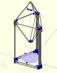
Emmett-Delta

Discussion in '3D printers' started by David Bunch, Jan 8, 2016.

  1. Cobalt Griffon

    Builder

    Joined:
    Oct 5, 2015
    Messages:
    20
    Likes Received:
    0
    Hi David,
    The fit on the corner brackets was just perfect, towers went in with no issue that a little persuasion from a rubber mallet couldn't fix ;) the extra spacing on the tightening gap would definitely be a good idea, I've got mine tightened to the point that they are slightly crushing the plastic to get a completely tight fit.
    Edward
     
  2. David Bunch

    David Bunch Veteran
    Builder

    Joined:
    Oct 27, 2014
    Messages:
    624
    Likes Received:
    433
    I have added the internal Frame option to the Github. The openscad source should be able to create almost any size internal frame. I created a sample frame for 210mm Build plate & 300mm Build plate since they are probably the most used. I currently only made this to work with 1/2" EMT Horizontal & Vertical, but could adapt it to the other build options if someone want it. I have only printed the test part to make sure the holes & dovetails work for me.

    There are a few variables you can change, but mostly you should only need to change the 2 variables:
    Build_Plate_OD = 210; //Diameter of Build Plate
    Mid_Leg_Qty = 0, 1, 2 or 3

    Emmett-Delta/EMT12_Horizontal_EMT12_Vertical/BottomFrame at master · geodave810/Emmett-Delta · GitHub
    BottomDoveTailFrame_210mmOD_Rev28.jpg BottomDoveTailFrame_300mmOD_Rev28.jpg
    I also made a couple of minor changes to the vertex parts for this 1/2"EMTH & 1/2"EMTV build:
    Emmett-Delta/EMT12_Horizontal_EMT12_Vertical at master · geodave810/Emmett-Delta · GitHub
     
  3. David Bunch

    David Bunch Veteran
    Builder

    Joined:
    Oct 27, 2014
    Messages:
    624
    Likes Received:
    433
    One thing I missed while looking at the assembly of all the parts is the Heat Bed Bracket hits the Dovetail Frame. I should be able to fix that. I need to add that part to the dovetail frame openscad file for future checking.

    Here is what the problem looks like. I circled the problem areas in Red.
    HB_BracketHitsDoveTailFrame.JPG
     
    MaryD likes this.
  4. David Bunch

    David Bunch Veteran
    Builder

    Joined:
    Oct 27, 2014
    Messages:
    624
    Likes Received:
    433
    This turned out to be easier to fix than I first thought. This change also shaved a little plastic off the offending parts.

    BottomDoveTailFrame_210mmOD_Rev30.jpg BottomDoveTailFrame_300mmOD_Rev30.jpg
     
  5. fr0sty

    fr0sty New
    Builder

    Joined:
    Oct 7, 2018
    Messages:
    16
    Likes Received:
    1
    David,
    Thanks for all the work you have put into this design! I've read through the Cobalt Griffon's build log, printed a few test pieces to prototype the linear motion and am starting to sketch out an actual build. I'm planning to cut my conduit in quarters to make 30" towers, and having no more than a 300mm build diameter and don't anticipate trying to push extreme speeds.

    Can you tell me what configuration you would recommend starting with? I printed one of the 1/2" x 3/4" vertexes (the big one) from github as a test, but I see that there is also a slimmer V2 version and that the 1/2" x 1/2" is the most "recent" according to the README. I haven't bought any material for the horizontal members or the tetrahedron on top so I have no sunk costs.
     
  6. David Bunch

    David Bunch Veteran
    Builder

    Joined:
    Oct 27, 2014
    Messages:
    624
    Likes Received:
    433
    I never actually built a final end product of this design as it did not seem that cost savings to me, but if you are only going as large as 300mm build diameter, I think the version using 1/2" EMT for the horizontal & vertical pipes should work.
    geodave810/Emmett-Delta

    Rather than printing the large vertex parts to test, I would suggest printing 3 of these Heatbed mounts & put two of your 1/2" horizontal EMT's of the length you are using between them. 2 of the heat bed mounts at the ends will represent the vertex parts & 1 in the middle where the heat bed or build plate would mount. It should only take 2 to 3 hours to print those parts.
    geodave810/Emmett-Delta
    That should give you a very good idea of how sturdy it will be.

    Also those brackets use 25mm between the pipes, if you use the Tall bottom vertex parts, which are 42mm between pipes, you will need a different bracket. I could probably draw one of those up if you need it.

    Post some photos when you make progress on it.
     
    #66 David Bunch, Oct 8, 2018
    Last edited: Oct 8, 2018
  7. fr0sty

    fr0sty New
    Builder

    Joined:
    Oct 7, 2018
    Messages:
    16
    Likes Received:
    1
    So put three holders at both ends+middle of a side-span to assess rigidity, is that right? Sounds easy enough.

    It's looking like I'll be going with the 'short' 1/2x1/2 from github unless something surprising pops up.

    I attached a photo of my linear motion mock-up. My plan currently is to adapt the "CherryPi IIIs" effector setup to work with these carriages. That design uses ball/sockets tensioned with Spectra line and a spring rather than using magnets or Traxxas ends like most other designs.
     

    Attached Files:

    #67 fr0sty, Oct 8, 2018
    Last edited: Oct 9, 2018
  8. David Bunch

    David Bunch Veteran
    Builder

    Joined:
    Oct 27, 2014
    Messages:
    624
    Likes Received:
    433
    This image is what I had in mind. Add 3 screws to tighten the brackets to the pipes & try to compress the pipes together. That should give you a good idea as to how strong it will be. Cobalt Griffen has already proved that the verticals will work.
    EMT12_Test.JPG
     
  9. fr0sty

    fr0sty New
    Builder

    Joined:
    Oct 7, 2018
    Messages:
    16
    Likes Received:
    1
    Tests with the clips was promising so I went ahead and printed the lower vertexes. Do I understand correctly that the design is now intended for "no drill" assembly? Is just the friction of the clamping parts sufficient, or is the intention to screw the vertexes down through the central hole?
     

    Attached Files:

  10. David Bunch

    David Bunch Veteran
    Builder

    Joined:
    Oct 27, 2014
    Messages:
    624
    Likes Received:
    433
    You made a lot of progress quickly. Those are pretty long prints as I recall.

    You should be able to just use the brackets from: geodave810/Emmett-Delta & not have to drill the pipes. You will need 1 or 2 screws for each bracket depending on the style you use & 4 brackets per vertex or 12 total brackets. I sized the bracket holes for M4 or #8 screws. I am not sure of the lengths of the screws you need. I tested just using those brackets & they felt pretty secure to me, but I did not ever test them printing since I did not build a final machine. Before doing all the brackets, you might want to print 4 of them & see how sturdy it feels with 2 pipes on 1 side of 2 vertex parts.
     
  11. fr0sty

    fr0sty New
    Builder

    Joined:
    Oct 7, 2018
    Messages:
    16
    Likes Received:
    1
    I think they were just under 3 hours each but my print settings are somewhat aggressive: .3mm layers, .6mm extrusion widths and 80mm/sec print speed. They won't win any beauty contests, but they should be plenty strong. I need to buy a few more lengths of EMT and cut a few horizontals.

    I attached a mock-up of the effector. I used bamboo skewers and printed ball ends for the proof of concept and I'm somewhat tempted to see how far I can get with that choice. I do have a source for aluminum rods and a supply of acetal balls for when I come to my senses, though...
     

    Attached Files:

    #71 fr0sty, Oct 9, 2018
    Last edited: Oct 9, 2018
  12. fr0sty

    fr0sty New
    Builder

    Joined:
    Oct 7, 2018
    Messages:
    16
    Likes Received:
    1
    Cut and partially assembled my towers. Fit ended up being a bit tight, but some trimming and gentle persuasion seem to have done the trick. Need two more top vertexes and to decide on a length for the side pieces.

    I mocked it up with 16" sides (as suggested by the calculator for 300mm build diameter) but it looks far too wide. My tower pipes are 760mm, what is a reasonable width?
     

    Attached Files:

  13. David Bunch

    David Bunch Veteran
    Builder

    Joined:
    Oct 27, 2014
    Messages:
    624
    Likes Received:
    433
    Its looking good. You might want to test fit a slider carriage on one of the columns to see if you have any separation of the pipes where the wheels run over. At 30" height you might be ok, but Cobalt had to add some epoxy or some sort of glue to the inside of the 4 pipes to correct that. For my printing, I am using variable layer heights with the Slic3r Prusa Edition & running my Makerfarm 10" Prusa i3v at 150mm/sec using the klipper firmware. Are you familiar with the klipper firmware? Glad you were able to get the pipes in. What kind of plastic are you using? That looked like PETG in your photos.

    The effector with the bamboo looks interesting. I will be interested to see how those work. It always interesting to try new ideas.

    Is that the spreadsheet calculator you are referring to? Since you are going with 300mm build plate are you using one of the seemeCNC heatbeds? I also did an openscad calculator for this Emmett using a different configuration, but might be able to figure out what it would be for this configurarion. What is the diameter of your hole patterns for mounting your build plate?
     
  14. David Bunch

    David Bunch Veteran
    Builder

    Joined:
    Oct 27, 2014
    Messages:
    624
    Likes Received:
    433
    Here is an image showing the SeeMeCNC 300mm hole diameter heatbed & I get 16.58" for the side lengths when I drew it graphically in Draftsight. See if this looks correct. The spreadsheet showed 16.628" which is only off by 1.2mm for that distance. I will have to look back on what numbers I used with that spreadsheet.
    Emmett_300mmDimensions.jpg
     
  15. fr0sty

    fr0sty New
    Builder

    Joined:
    Oct 7, 2018
    Messages:
    16
    Likes Received:
    1
    I pulled at the pipes with my fingers and can't get much deflection. deflection goes up as the square of the length, If I start having trouble I plan to drill across the diagonals in the middle of the span and clamp it with machine screws.

    I have heard of Klipper but haven't looked into it much. I like the concept.

    Parts aso far have all been PLA. I should have test fit one of the vertexes before printing the rest. The original 1/2"x3/4" piece that I printed fit like a glove these new ones are all a little tight. I'm trimming the inner bores a bit but they need a lot of persuation which is not ideal. My guess is I started overextruding at some point (need to measure filament and check flow settings). If I ever get past the proof-of-concept stage I'll probably reprint some of the parts in PETG, but I haven't messed with that material yet.

    I'll be certain to let you know. I have the bamboo 'in stock' and it's really easy to work with so I'm going that route until I can get the printer moving under its own power. I fully expect to move on to Al/CF rods when things get serious, but I'm open to being surprised.

    Yes, I used your spreadsheet. I don't have any bed (heated or otherwise) yet but 300mm was one of the defaults and seemed about as big as I can imagine needing at this point.

    Seeing that image helps a lot. My mock-up didn't have anything standing in for the build plate and I think I was visualizing less than 5" of space between tower centers and the edges of the build volume which threw off my mental proportions. I'll lay it out on the floor again (including a build-plate mock-up and see what I think).

    Mark
     
  16. David Bunch

    David Bunch Veteran
    Builder

    Joined:
    Oct 27, 2014
    Messages:
    624
    Likes Received:
    433
    Instead of using PETG, you might want to look at esun PLA+. It has a lttle bit of flex, but not as much as PETG. I have not printed with anything else for over a year & it prints better than regular PLA to me. Here is the link from US importer, but I usually buy it from amazon as they usually have 1 or 2 of the colors discounted.
    eSUN PLA+ Filament 1.75mm 1kg (2.2lb)

    Here is a short video of my machine printing at 150mm/s with Klipper. Since it is not a large part, it does not get the full 150mm/s speed with acceleration/decelerations.
     
    GrayUK likes this.
  17. fr0sty

    fr0sty New
    Builder

    Joined:
    Oct 7, 2018
    Messages:
    16
    Likes Received:
    1
    If klipper supports Delta kinematics I'll give it a shot.

    I mocked up the linear motion on one of the towers to get an idea of how I want to design my carriage. Only had a scrap of belt so I made up the difference with Spectra. IMG_20181011_192756242.jpg IMG_20181011_192916712.jpg
     
  18. David Bunch

    David Bunch Veteran
    Builder

    Joined:
    Oct 27, 2014
    Messages:
    624
    Likes Received:
    433
    Your delta is looking good. Yes, Klipper supports delta kinematics. On a Delta machine is where it really shines as you can use 8bit controllers on it & get the 32bit speed from the raspberry pi that the heart of klipper runs on. I have a Folgertech delta with an 8bit MKS board I want to put it on, but have not gotten around to configuring it yet. From his features document, "Automatic delta calibration support. The calibration tool can perform basic height calibration as well as an enhanced X and Y dimension calibration. The calibration can be done with a Z height probe or via manual probing" Here are his current features:
    KevinOConnor/klipper
     
  19. fr0sty

    fr0sty New
    Builder

    Joined:
    Oct 7, 2018
    Messages:
    16
    Likes Received:
    1
    Quick update:
    • Got a Pi 3 coming in the mail so I can try Klipper.
    • Cut my horizontals to 'size' (there is some variation).
    • Printed the 'test-fit' piece for the frame brace. Need to tweak my setting a bit for a good fit.
    • Printed large limit switch holders, but I want to reprint to use the smaller microswitches.
    IMG_20181010_195107757.jpg
     
    joe williams likes this.
  20. David Bunch

    David Bunch Veteran
    Builder

    Joined:
    Oct 27, 2014
    Messages:
    624
    Likes Received:
    433
    You are coming right along. There is a Klipper facebook group called "Klipper 3d Printer Controller Firmware" that should be helpful to you if you run into any problems setting up Klipper.
     
  21. fr0sty

    fr0sty New
    Builder

    Joined:
    Oct 7, 2018
    Messages:
    16
    Likes Received:
    1
    Question about this bit:
    geodave810/Emmett-Delta

    I printed this piece previously and it was a very tight fit but I think that was mostly due to overshoot and bulging of the corners (plus a little overextrusion, perhaps). I started a new roll of filament, tweaked flow/acceleration/jerk to clean up the corners and tried again and now the fit is incredibly sloppy (when mated the parts have at least 1mm of slack).
    Is that how it is supposed to be? I printed a quick calibration cube which was spot on dimentionally so it appears the slack is built into the STL, but I can't say for sure.
     
  22. David Bunch

    David Bunch Veteran
    Builder

    Joined:
    Oct 27, 2014
    Messages:
    624
    Likes Received:
    433
    If you are referring to the dovetail connections which sounds like you are, the default tolerance is .3mm. In the openscad file you can change that from .2mm to .4mm. You should not get 1mm of slack with that tolerance. Here are the dimensions of that joint connection & I downloaded the STL file from there so I would be sure that was what I thought it should be. I attached an image showing the dovetail dimensions & also a STL file with a .2mm clearance. If you need a tighter fit than that, I could add a couple more even tighter tolerances. It should be a tight fit between those parts.

    To change that tolerance in the openscad file, it is line 41 in BottomDoveTailFrame_Rev30.scad
    DT_Size = 3; //4 = .4mm clearance
    //3 = .3mm clearance (Default)
    //2 = .2mm clearance

    Let me know if that helps or if I missed what you were referring to.
    DoveTailDim.jpg
     

    Attached Files:

  23. fr0sty

    fr0sty New
    Builder

    Joined:
    Oct 7, 2018
    Messages:
    16
    Likes Received:
    1
    I think we are on the same page. When I say 1mm, I mean there is 1mm gap between the mating faces when pulled in the X direction (not that there is a 1mm gap between the teeth. Given that there a built in .3 at the back, and the shallow angle of the dovetails that doesn't seem beyond the realm of possibility, especially if my I'm under-extruding the walls a bit.

    I'll try the tighter one and see what that looks like. Thanks for the help!
     
  24. fr0sty

    fr0sty New
    Builder

    Joined:
    Oct 7, 2018
    Messages:
    16
    Likes Received:
    1
    Ok, I think I've got this new filament sorted out. The Rev30 test piece is a good fit now (and rev31 too tight) so I think I'm ready to move forward.

    What fasteners are supposed to fit in the nut traps and holes in the test piece? #8, correct? They seem to fit and M5s are a little snug in the bores.
     
  25. David Bunch

    David Bunch Veteran
    Builder

    Joined:
    Oct 27, 2014
    Messages:
    624
    Likes Received:
    433
    I was using either #8 or M4's in the openscad, but looks like STL files were generated for #8's & since they fit for you, that is what I would use.
     
  26. fr0sty

    fr0sty New
    Builder

    Joined:
    Oct 7, 2018
    Messages:
    16
    Likes Received:
    1
    Got the braces printed out this weekend and they look good. The existing STL didn't fit on my print bed so I made my own .stl from the .scad with the following changes:
    1. Change build diameter from 210 to 300, didn't change any other parameters.
    2. Only generate one of the cross bars instead of three. You need to print two more sets of the arms anyways.
    3. "Right justify" the parts so they fit better. Before the bottom two parts projected out an extra 5mm or so.
    Had a few initial failed prints due to bed leveling challenges with such a large print, but got three successful prints in a row once things got adjusted.
    IMG_20181105_074542006.jpg
    What prevents the nut from backing off when the bottom frame is attached to the vertexes? There are no nut traps. Should I be gluing them down? Adding lock washers?
    IMG_20181105_075317899.jpg IMG_20181105_075324775.jpg
     
  27. David Bunch

    David Bunch Veteran
    Builder

    Joined:
    Oct 27, 2014
    Messages:
    624
    Likes Received:
    433
    I usually use Locknuts instead of regular nuts. Lockwashers should work with the regular nuts instead of just using locknuts. I can see where you would not want to use locknuts since your bolts extend quite a bit beyond the end of the nut. I personally do not like to glue things like this together in case I want to take it back apart for upgrade or something.
     
  28. fr0sty

    fr0sty New
    Builder

    Joined:
    Oct 7, 2018
    Messages:
    16
    Likes Received:
    1
    I've got some shorter screws, those are just what was handy.

    My concern on the bottom of the vertex is that with no way to retain the nuts and no access once the tubes are replaced I would be in some amount of trouble if those screws worked loose (or if I needed to remove/replace the bottom frame for some reason). Retightening would require dismantling basically the entire printer to get at those nuts which doesn't sound like fun. Hence why a nut trap around them could be a nice addition.

    I might toy with adding one if I need to reprint those bottom vertex parts again (or even printing and gluing in supplemental ones to the existing pieces for my peace of mind.
     
  29. David Bunch

    David Bunch Veteran
    Builder

    Joined:
    Oct 27, 2014
    Messages:
    624
    Likes Received:
    433
    I see what you mean. Glue or Loctite might be your best option then. I have never used Loctite though. If you redesign it with nut traps, I probably do not need to tell you this, but do some small test prints with the traps to get the size that fits best for you.
     
  30. David Bunch

    David Bunch Veteran
    Builder

    Joined:
    Oct 27, 2014
    Messages:
    624
    Likes Received:
    433
    I was thinking about your problem this morning & came up with the idea to glue these nuttraps into the bottom vertex parts where the nuts that hold the bottom plate come thru are attached. This keeps you from having to glue or Loctite the nuts. I called it M4_NutTrap, but think I sized it for the #8 nuts & screws, but it is a simple print to test. I am attaching the .scad & STL file & a screen shot to show it. If I did not get the dimensions correct, you can easily adjust them in the openscad file. I ghosted a 1/2" EMT to show the fit.
    M4_NutTrap.JPG
     

    Attached Files:

Share This Page

  1. This site uses cookies to help personalise content, tailor your experience and to keep you logged in if you register.
    By continuing to use this site, you are consenting to our use of cookies.
    Dismiss Notice