Welcome to Our Community

Some features disabled for guests. Register Today.

myOX : a 4' x 2' OX with potential

Discussion in 'CNC Mills/Routers' started by Serge E., Jun 19, 2014.

  1. Balu

    Balu Well-Known
    Builder

    Joined:
    Apr 14, 2014
    Messages:
    81
    Likes Received:
    30
    Could you update your initial post with the plans and some more photos? Your project looks a lot like something I have in my mind for a while now, but never started because I'm lacking the knowledge and time to finally start it...

    My basic idea is to build something with an about 1000 mm wide work area and an "unlimited" length like you mentioned. I liked the concept to not move over a fixed area, but feed the material like the phlatprinter does. I'm not sure about its roll-"pinching" mechanism though.

    I'd also prefer some rack and pinion mechanism instead of a belt driven system. I know a lot of people use it, but to uninformed me it just does not feel right somehow.
     
  2. Serge E.

    Serge E. Journeyman
    Builder

    Joined:
    May 6, 2014
    Messages:
    730
    Likes Received:
    252
    I will be adding pictures and other details now that MyOX is almost ready to come to life. It's been and it continues to be a great learning adventure especially when considering I rushed into the project and missed a few details even with the minor changes done to the original OX plan (size).

    Changing to a rack and pinion can come later. The belt drive is a good start ... A low cost option. I know, I keep thinking the belt can only stretch with time. One thing, it could be more forgiving if we, as green as we are, do something we shouldn't .... I'm thinking a chain drive might be ideal, but there can be "play" like in the belt, maybe more ?

    I am still quite green ... I feel like Kermit (the frog) about to break into the song ;))

    Have big plans but start with the basic design and maybe a few basic mods. Size is the "easiest". The rest can come with time, like a feed mechanism. When I'll get to working on pieces larger than the 4' x 2' work area, I'll feed manually at first. See how things work, do some research and mind picking. How to automate will come soon after. I also plan some form of a 4th axis. Again, manual at first (few fix position to work "sides" of a project as seperate jobs with "easy" alignment). I will have myOX go bottomless at first : mount work pieces which are deeper than the Z-axis. That mount will be the first stage to the 4th axis. I have lots of plans and ideas in the space between my two ears. I'm still (seriously) thinking about the poleOX ! (Yes, it now has a name. I've said too much ...)

    There is no rush, so time is not really an issue. As for knowledge, there is plenty of people here to answer questions and help with suggestions. The resources are also good to browse (which I didn't really do). It is a learning experience, knowledge is gained along the way. Part of DIY and Open Source is to gain and share knowledge so others can give it a try without having to figure everything out from zero. There was no way, in my mind, that I could of come up with a CNC design from scratch... So a big thanks to all who have and those who will help me in my adventure with myOX and other projects this is leading me to imagine and, most important, build (at some point).

    This is the future ...
     
    Balu likes this.
  3. Jonny Norris

    Jonny Norris Well-Known
    Builder

    Joined:
    Aug 17, 2014
    Messages:
    495
    Likes Received:
    95
    Optical home switches on every gantry and frequent g code homing coupled with Mach 3s capability to auto zero will compensate for stretch during jobs with regular axis calibration belt stretch shouldn't be too much of a concern I wouldn't have thought.
     
  4. Serge E.

    Serge E. Journeyman
    Builder

    Joined:
    May 6, 2014
    Messages:
    730
    Likes Received:
    252
    I'm back. Been kind of staying away from the computer to work on myOX and have it ready for chip making between work, wife, life, ... not necessarily in that order.

    While deciding on getting Chris' (Laidlaw) router mount, ordered it late last week and arrived at pickup point this afternoon, I have been tweaking myOX ... playing with how to dress it up a bit:
    • figured a way to mount the controller (CNC xPro) on outside of a Y gantry plate, instead of the X axis track (lots of 'dust' is more likely there)
    • figured paths for all of the cabling (Y is "fixed", X and Z in split loom and tracking), some dressing and hiding loose cables
    • prototyped 1/4" thick bent Lexan "shields" for both Y axis - protects controller, ... Venting with fans in the works (I have .03 polycarbonate to thermoform a "final" version)
    • built a custom workbench to host myOX, power supplies, storage for bits and such, ... not forgetting the emergency switch and the likes. I'm no cabinet maker, but it looks nice w/o finishing touches.
    Took a few pictures along the way, some key notes for the Lexan bending, etc. I need to spend a couple of hours or more to clean the stuff and share it all. Hopefully sometime this weekend ...

    Build is finally almost "complete". It's been a slow build, not giving it all the time I should off, but the journey was a thrill.

    The next journey will be using myOX ... making some worthy wood, plastic and maybe aluminum chips real soon now, I hope ! I really need to show the wife the value of having one of these babies in the garage. ;)

    The DIY bug has bit me ... don't cure me, this is good !
     
    Balu likes this.
  5. Serge E.

    Serge E. Journeyman
    Builder

    Joined:
    May 6, 2014
    Messages:
    730
    Likes Received:
    252
    Yes ! myOX is ...almost... ready to generate piles upon piles of wood chips ... and, of course, work of arts ! :cool::)

    Here's some long awaited photos (finally !)

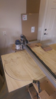
    P9132381 - myOX on its custom workbench.JPG

    The myOX workbench is purposely low (about 30") so it can be stored, with myOX, beneath the other, partly seen in right corner of above photo. Lockable heavy duty casters are in the plans. For now, the wife doesn't mind close proximity to her car, just off camera to the left. (Wait 'til the chips start flying, eh ?)

    Controller (CNC xPro) is all wired up to the 4 steppers and all steppers are stepping ... :oops: I just need to invert one coil on some steppers, especially the 2nd Y stepper, so they all go in the right direction :duh:. Darn details, eh ?

    The CNC xPro is the best :thumbsup: ... so far. It will soon enough prove itself ... I can't wait. So close, yet so far. :nailbite:

    P8242311 - myOX CNC xPro controller in place.JPG P9132374 - myOX CNC xPro controller - being wired and dressed.JPG P9132375 - myOX CNC xPro controller - closeup.JPG

    Did you notice the (prototype) Lexan shield ? Had to find myself a heat gun (details to follow) . The final product will be cut with ... yeah ... myOX. The prototypes, three in all, were done on the table saw, eye balling the cuts ! A milled version is planned with proper slots to for power, USB and fan(s) to keep the air moving while chips should be kept out (in theory).

    Here's an other view, even has a cover (just bottom is opened at this point) : P8242310 - myOX - prototype lexan shield.JPG A twin shield is at other end, just to keep a balanced look and chips out of the other Y-axis stepper area.

    A few other photos :
    Workbench top taking shape : P9082370 - myOX workbench top frame.JPG to become : P9132381 - myOX on its custom workbench.JPG Bottom shelf will be home for some of the tools and other loose ends (including the thermoforming project also being worked on). The power source will be tucked away beneath, along with the computer (maybe on a pull out shelf of some sort... The centre top portion is already cut to open up (about 2' wide) for the eventual 4th axis (manual at first) to work all sides of a work piece.

    Trick question : in looking at the setup, rather than putting some cross members (about 1/3 and 2/3 of width) for stiffening the myOX frame, I'm thinking of fixing myOX to the workbench (maybe 3 double corner brackets front and back ?) Will that be enough to keep it square and solid ? The thought is I gain a good 1-2 " of work height. I will have a drop in "heavy" MDF (?) 3/4" board to sacrifice when cutting a little too deep. Early on, unfortunately, I did cut a V-slot for cross members. So I will use them near the Y-axis beams for extra stiffness... They would be just at limit of cutting area, so ... a few inches inwards from Y-axis beams. The idean is the sacrifice board should fit snug between them, maybe with two corner brackets each for a firm out of the way grip of that board ...

    2nd trick question : to hold the work piece, I was thinking of doing a couple of "sliders" made of v-slot tightened with corner brackets to the main frame. They would slide in X-axis. Each "slider" would have a couple of corner brackets to "corner pinch" the work piece in Y-axis. I'll have to figure out some "quick" tightening trick... Would that work ? :rolleyes:

    myOX ends up being 68" x 30 ": P9132377 - myOX being wired.JPG P9132378 - myOX stretches for nearly ever.JPG P9132379 - myOX cable track looks good.JPG P9132380 - myOX wiring is almost done.JPG The workbench top is about 78" x 30 1/2". I know, kind of tight. However, the wife wanted to see the pile of leftover wood and OSB pieces reduce NOT grow ! Noticed how the 2" x 4" are laying on their side ? I needed about 6" to 'strech' the 24" OSB pieces :jawdrop: There's an other frame below, those 2" x 4" being upright to reduce flexing ...

    Of course, the cutting area is "only" about ... 52" x 25" or so, which is a tad better than the target 4' x 2' for myOX. The router and limit switches will tell better once up and working.

    Which brings up the next step : mounting the router and, you guessed it, the limit switches, the emergency switch, and a few extras of the sort. The router will be :eek: "real easy" to mount given I have Chris (Laidlaw) kit :thumbsup:. I can not be as confident about the limit switches :nailbite:. But I know I will need them, already in my initial tests, not having set the GRBL parameters "just right" ... I tend to go a little too far in all three axis. :duh:

    Well, I better get to bed If I want to be up early (in a few hours !) for ... work.

    I can already smell the sweet aroma of wood chips ...
     

    Attached Files:

    Jestah, Mark Carew and Robert Hummel like this.
  6. Jonny Norris

    Jonny Norris Well-Known
    Builder

    Joined:
    Aug 17, 2014
    Messages:
    495
    Likes Received:
    95
    Liking the lexan shield. Top job
     
  7. GrayUK

    GrayUK Openbuilds Team Elder
    Staff Member Moderator Builder

    Joined:
    May 5, 2014
    Messages:
    1,668
    Likes Received:
    627
    What a good job there!...:thumbsup:

    I thought it odd to begin with, having the long X and short Y, but now I see how you reduced the possibility of flexing. i.e. Because the long runs are in fact sitting directly on the workbench, whereas, my long run, Y, will be suspended on the front and rear pieces. If you know what I mean. :cool:
    Once again.... Good job!

    Gray
     
  8. Serge E.

    Serge E. Journeyman
    Builder

    Joined:
    May 6, 2014
    Messages:
    730
    Likes Received:
    252
    Yes ... sort of. I'm just worried about the other possibility of flexing : weight of router and forces working against it and the long X axis. It is, currently, a double beam of 20x60. I suspect I'll have to take apart & slip in a few of the joining thingofabob (excuse my use of highly technical terms, I'm new to all this) to be true twinned beams. If my router is too heavy, I might have to go to double 20x80 thingofabobed beams or :nailbite: tripled.

    But, as you say, the Y axis, carrying the rest of the machine, should not be affected by much flexing in my configuration.

    The main reason for my choice, to be honest, was to get a "throat" of at least 4' wide where a work piece could slide through so I could work on something of ... technically ... infinite length. Ok, a full size door (not the garage door mind you, it would be too wide ... then again ... I could work on a section of one at any one time.)

    First, let me try doing a keychain or something real quick with little requirement for high precision and no comments from the wife other than "is that all it can do ? I could of done with a kitchen knife !" ;)
     
  9. Serge E.

    Serge E. Journeyman
    Builder

    Joined:
    May 6, 2014
    Messages:
    730
    Likes Received:
    252
    Thanks. And to think I eyeballed most of it too ... me and both of my nearly blind eyes ! First attempt was just off by too much, second attempt was "oh, so close, but no cigar" and third time was a charm, fits like a pair of skin tight jeans (how does anyone get in or out of those anyways ?)

    Guess what ? In trying to quickly drill a hole to pass the USB B female connector to the xPro, having it too far to the left my a fraction of an inch, not wanting to take the whole thing apart, I almost distroyed both a near perfect Lexan shield AND the xPro !! :banghead: My gardian angel must of been on duty at the time, or some of those weird laws of nature saved me. The 1/2" drill bit just pushed the xPro while both of the tiny/short M3 screws strip the thread in the Lexan backing holding the controller to the shield ... Man was I happy !!

    Like the "measure twice, cut once", there's the "take your time, do it right/properly the first time !"
     
  10. Serge E.

    Serge E. Journeyman
    Builder

    Joined:
    May 6, 2014
    Messages:
    730
    Likes Received:
    252
    Well I do have a problem, two in fact, before I can "finish" myOX.

    Remember way back at the beginning of this build I mentioned having problems getting some screws ? I had to use longer screws for the 6 V-wheels of the Z axis. I figured the extra length would eventually come in handy for ... whatever. Right ?

    NOT ! It seems they are just 1 or 2 mm too long and the beautiful router mount made by Chris will rub against these darn screws. The easy way out would be to cut :jawdrop: a piece off each screw without taking anything apart. Ok, maybe just file the couple of mm that are in the way. But those aren't just plain old steel, right ? Fine metal dust is not a nice thing to have... Getting the old grinder out is rather drastic as well.

    However, the second problem is that my Z axis is way too loose. I mean it should not be loose at all ! Could it be these long screws just not helping ? I tried adjusting the 3 eccentrics. Two of the 3 wheels make nice contact. But the third is just not cooperating with me. So I ordered three 'spare' eccentrics not long ago. Now, do I change just the top one ? Do I use them making all 6 wheels with eccentrics ? That would make it difficult to get a nice perpendicular alignment with the table, no ?

    I don't remember it being so loose at any point thus far. That's the real odd thing about it ...

    So myOX is facing a major operation, having to disassemble one Y axis gantry plate, slide the Z axis assembly off the X axis, take apart a fair bit of the Z axis assembly and figure out the best solution to make it all nice and solid before reassembling. Again, someone is looking over me here, except for loose Z-axis, since I have a good 6" or so of slack wiring at the far end Y axis stepper/gantry. Wiring for that stepper goes through a V-slot to be out of sight ... I just love it when everything falls in place on its own like that. Don't you ?

    How can I make the Z-axis nice and solid ? Could it be the piece of 20x60 which might be out of spec ? Maybe a wheel is off spec as well ? It can't be just the cooler temperature of late ? It is cold, for the season, especially in the garage, but not that cold.

    By loose, I mean it can be moved front to back and side to side by a lot more than what one would expect for such a tool and without even trying hard. :eek:

    I would welcome your thoughts and, mostly, your suggestions to fix this.
     
  11. GrayUK

    GrayUK Openbuilds Team Elder
    Staff Member Moderator Builder

    Joined:
    May 5, 2014
    Messages:
    1,668
    Likes Received:
    627
    I'm sure you've tried this, but what about process of elimination?
    You know one wheel is loose, so take a good one and swop it over, and put the loose one in it's place. Does the error follow the old loose wheel, or is the error still at the same point?
    Just a thought.
    Gray
     
  12. mybuild14

    mybuild14 New
    Builder

    Joined:
    Mar 20, 2014
    Messages:
    23
    Likes Received:
    5
    I am having the same problem with my Z-axis. Its like there is not enough adjustment in the 3 eccentrics to remove all the play. I am using 20x40 so the problem is not the 20x60 out of spec. May have to use eccentrics on all 6 wheels and switch to 20x60?
     
  13. Serge E.

    Serge E. Journeyman
    Builder

    Joined:
    May 6, 2014
    Messages:
    730
    Likes Received:
    252
    I thought about that, but it involves taking the Z assembly off to access the screw heads. So I am kind of hoping for some fairy dust magic before going there :nailbite: I suspect I won't have must choice. If it comes to that ... man ... I don't want to :cry:

    So here is a thought, for next time, triple check it all before "final" assembly BUT thinking SERVICEABILITY : how to make it "easy" to change a wheel and such ? Like the old car engines : to change a spark plug one just reached in and did it ... these days, with all the wonderful engineering, one sometimes need to dismantle half the engine to get to the one spark plug which fails. I heard changing bulb in some newer cars involves taking OUT the entire bumper which means taking out tires and ... :duh:

    Maybe I should of got the correct length screws and have the heads facing out ??

    Shortcuts sure don't pay in the long run, eh ?
     
  14. Serge E.

    Serge E. Journeyman
    Builder

    Joined:
    May 6, 2014
    Messages:
    730
    Likes Received:
    252
    In bit of reading prior to starting building myOX I read that using the 20x60 would be better. Like the wide stance of rally cars. Come to think of it, they (rally cars) sit low as well. Thus my idea of adding a couple of inches in height might not of been great ? But I wanted (read : needed) as much extra Z as possible (newby thought). myOX, as I see it, is supposed to mill me mold forms of at least 6-8 inches in lesser dimension as well as the usual fun engraving, etc.

    Here's a thought : maybe I should of started with the "base" design, work out bugs (ie. get confortable with the whole concept as others, more experienced, did) then "enhance" the design? Sure, width / length are easy to tweak, beyond any flexing. But mess with Z and you are looking for trouble. Or is it just being green ??

    I should of remembered : "learn from the mistakes of others"

    How can the Z be improved upon for more height/depth ... Without breaking the bank ? I'm thinking if double X beams help with the flexing there, some even had thought of building up a sort of H configuration there, could this also help on Z ?? Catch is one needs to mill new plates to try concept. Thus back to proven " base" model to prototype a "better" model. Sounds too simple to make sense, eh ?

    Longer Z might need more wheels spaced further apart ... Wheelbase could be a part of the problem here ?

    So off to the operating room myOX is going ... As stated in my early writings, this might become a frankenOX before I'm done with it ! The oversized (length) bolts already stick out of its neck ...
     
  15. Serge E.

    Serge E. Journeyman
    Builder

    Joined:
    May 6, 2014
    Messages:
    730
    Likes Received:
    252
    Drying my tears, I had one more look before heading off to work ...

    It may just be that some of the wheels on my Z are not tight enough (just maybe ?) Trying to adjust the 3 eccentrics is just not doing enough, although I got it a little tighter, there is still way too much play for any kind of quasi precision work.

    The (somewhat) good news, is that I don't have to disassemble the entire myOX to service the Z wheels.

    The not so great (nor bad) news is I can just remove the front X plate and all of the Z components can be pulled out (given slack of the wiring - note to self : maybe some quick disconnects for all of wiring at steppers and switches ?)

    It would be way nicer to have the wheels' screw heads facing out, thus just a matter of taking the wheels out for quick service of a part which might wear out quicker than we think ?

    Oh, wait a second ... The ACME/lead screw is also there through the block fixed to the X front plate. Maybe those two screws should also be facing outward, needing nuts out back instead of in the block.

    So all that holds the Z axis are the wheels (relatively soft material) and the ACME/block acting more or less like a pivot point.

    Maybe that block should be much taller? There's plenty of room (height on X plate) ... in fact, make it one piece with the two wheel spacer blocks. That would give 8 screws to hold it firmly against the X plate. Tweaking the X front plate a tad, one can then space apart those wheels for a wider stance on the 20x60. Make the new spacer/ACME block about 2 cm taller (=height of front X plate, Chris' at least) and have option of adding a 4th wheel on either side. Maybe have the eccentrics distributed : each side with two eccentrics, instead of all on the same side ? Or just spread the 3 wheels further apart ... still alternate the eccentrics (2 on one side, 1 on the other) ... Just thoughts of a beginner, mind you.

    You know, with quick connects for the wiring of the Z stepper and four quick release "bolts" (like those used for the bicycle wheels, but to scale), the whole Z assembly could become a quick change tool head assembly ! Want to mill : snap on that spindle. Want to route : snap on that router. Want to laser cut : snap on the laser. One would need a double X front plate avoiding to realign the X wheels each time (ooops, keep in mind I am a beginner).

    There's food for thought anyways.
     
  16. Rick 2.0

    Rick 2.0 OpenBuilds Team
    Staff Member Moderator Builder Resident Builder

    Joined:
    Dec 20, 2013
    Messages:
    2,892
    Likes Received:
    1,551
    So many questions.....

    First as to how to design for serviceability, Look at how Mark built out his Z-axis mount on the Stinger V. Everything applies from the outside, everything adjusts from the outside. And you needn't be in a position of milling the fancy little blocks he is creating. A simple washer is more than enough of a standoff for the wheels from the attachment blocks. The only thing you do have to be able to accomplish is the horizontal slots. Simple router jigs can accomplish this.

    Filing off the ends of the screws probably won't make a difference in allowing the router mount to pass. (When you take half of a wheel thickness and add the depth of a nut, you are past the 10mm allowable from the centerline of the V-slot outward and thus any plate you attach flat to the face of the V-slot will hit the nuts.) Adding a thin shim between the mount and the Z-axis rail is probably the best solution. Filing off the back edge of the mount where the conflict occurs is also a possibility.

    Finally, as for the Z-axis height. It appears you have far more length on your Z-axis rail than you can ever make use of. When you lower the Z-axis to the bed, anything length left above the wheels doesn't do anything for you. (Just a consideration at this point.) As far as the wobbly bolts and the lack of adjustment, the fixed holes can be drilled out and offset spacers installed. Just be sure one side is adjusted exactly the same before you start adjusting the other to fit the rail. Ultimately however, you might be better off rebuilding it like Mark did in the Stinger V. Yeah, that will be a fair amount of work, but everything you set right now is something you don't have to fix later. :)
     
  17. Serge E.

    Serge E. Journeyman
    Builder

    Joined:
    May 6, 2014
    Messages:
    730
    Likes Received:
    252
    Yap ... tweaking the design so everything (or as much as possible) can be done from the outside (facing out) is a definte must. The only place were I need to do this is with the Z assembly - really just the 6 screws for the wheels and the two for the ACME block. An easy mod, it just has to be done early on. Like you say, anything done now to improve means not having to fix later

    Actually, Chris's tool/router mount comes with an added plate to sandwich between the Z v-slot and the actual mount. This gives plenty of clearance for the screws. In fact, of the 1 cm or so I have sticking outward from the wheel screws, only about, oh, 2.5 mm would need to be filed to clear the mount. But you give me an idea ... maybe I can just sneak in a spaceer to pull mount outward ... "cewl !" as the younger gen would say.

    I'll need to add photos, but check out some of the notes early on concerning my "design" : the centre of my work surface opens up ! So I could go down to the ground ... nearly 30". Ok, the workbench has a bottom shelf, so I could only go donw ... 24" or so. Still plenty of room for my puny 10" Z axis v-slot. I could work on pieces about 24"x 24" x 24", minus room to rotate that sucker if I want to work on all faces / multiple angles (even as a manual 4th axis). I plan on working maybe 12" thick objects : that's about 6" deep doing one pass per face. So I have plenty of room to reach that goal.

    Thinking about that ... But first, I will try a few simpler solutions when I get back from work tonight : check the eccentrics to see if they are ok (I might of damaged one as I normally tend to over tighten things and I do have 3 spares); maybe try some different configurations of the eccentrics (have one on one side, two on the other; not that it should really matter); etc.

    Thanks for the quick response ... it has given me some valuable ideas.
     
  18. Serge E.

    Serge E. Journeyman
    Builder

    Joined:
    May 6, 2014
    Messages:
    730
    Likes Received:
    252
    Well, after closer examination it looks like I have figured out why my Z-axis was way too loose.

    I had to take the Z assembly mostly off , which was way way "better" than having to take the far Y gantry plate off and ... :duh: I certainly did not want to go there, at any cost.
    P9162386 - myOX disassembling Z-axis for adjustments.JPG

    First, the screws holding the wheels with the eccentrics were not quite tight enough, especially the top one. It is not like me as people usually find I tighten things way too much. Given this build has been stretch over, what, 3 months now, I probably forgot to finish tightening the Z-axis. Quick check : all the other screws were just fine.

    Then, as I played with the possibilities, I noticed that one should not adjust the middle wheel eccentrics first ! It becomes a pivot point and there will be no way to properly adjust the top and bottom wheels eccentrics. Loosen the centre one, adjust top and bottom as best as can be done THEN do the centre wheel. It's not doing much, is it ?

    At this point, almost all of the looseness was ... GONE ! :):cool::)

    But there is still a bit of play. I don't like fact the wheel spacer block has (extremely) large holes, right through ! Yes, the eccentric itself needs a larger hole to fit properly. However that's just, what, 1/4" deep at worse ? So why have the larger hole go right through to the other side ... except for saving a step at manufacturing ? And, yes, a bit of room is needed at the other end for the magic to happen. I'm no expert, so I'll live it at that.

    So, the last bit needed to give a nice tight, yet not too tight, adjustment with the eccentrics is a tweak to X-axis front plate. I would move the holes for mounting the spacer block and the three wheels a tad inward. 1 mm is plenty, maybe 1.25 mm just to be safe ? At least those used when using a 20x60 Z, which are the ones I needed to use. This would avoid having to set the eccentrics near or at "maximum" inward position, which, evidently, does not quite make it.

    The above three adjustments should allow one to take all of side to side slack out and help reduce the front to back slack. To have the three pairs of wheels spread a bit more over the X front plate would also be great ..... maybe even allowing for an optional 4th pair of wheels (needing a taller plate). But that's probably me going overboard again as I aim to have even more Z travel down the road (or should I say down through my table).

    I would also make the two spacer blocks and the ACME block just one piece the full height of the X-axis front plate, just for good measure.

    My second problem, having the router mount more than touch the way too long screws I used to mount the Z wheels, would of been easy to fix if I had shorter screws. Even easier was to introduce two spacers for each of the four screws between the two plates used to fix the mount to the Z-axis 20x60 V-slot.

    P9162388 - myOX with Chris Laidlaw router mount and spacers.JPG Can you see them ?

    Here's how the router mount looks as it is put together on myOX : P9162387 - myOX with Chris Laidlaw router mount being assembled.JPG (bottom clamp on, which I moved up one position as my router has a substential bevelled edge at the bottom)

    Both clamps mounted, the mount itself fixed to bottom of Z's 20x60 gives the router the "perfect" working position :

    P9162393 - myOX router mounted .JPG P9162390 - myOX router with digital control.JPG Yes, the router has an LCD display. It displays the speed (steps, not continuous exact speed) and it is used to help set the proper routing speed depending on material and bit type/size.

    The router was 50% off and I had some Canadian Tire money (points) to reduce price down to something like only 70$ (with taxes). It's a MasterCraft Digital Plunge-Base Router (054-6902-0) : 12 amps soft-start motor (peak 2 HP), electronic feedback to help maintain constant speed, 10k to 25k rpm, 100% ball bearing, 3 LEDs, 1/4" & 1/2" collet/nut, and replaceable brushes.

    P8242309 - myOX - MasterCraft Digital Router main body.JPG P8242308 - myOX - MasterCraft Digital Router main body.JPG

    It is a tad heavy at 2.563 kg (call it a slim 6 pounds) side of choices for myOX, but the price was right :

    P8242307 - myOX - MasterCraft Digital Router on the scale.JPG Let's hope the NEMA 17 I picked can do the job ! :nailbite:

    Can you believe it's power cord is just the right length to snake it's way along the cable track and reach the edge of 'shield' near the electronics ? I'm still amazed how things tend to work themselves out even with my constant interventions.

    So, now I have all of the necessary mechanical, wiring and electronics put together in one big'ish OX : myOX !

    P9162392 - myOX almost ready.JPG

    Let's make chips !!! :thumbsup:

    Actually, now I have to figure out the proper settings for GRBL so steppers are stepping just the right distance in the correct direction ... I'll also recheck all the screws and such to be certain nothing is too loose ! :zipit:

    P.S. Anyone else reads "GRBL" as "garble" ? Doesn't it mean "distort" ? :confused:
     
    mybuild14 likes this.
  19. Serge E.

    Serge E. Journeyman
    Builder

    Joined:
    May 6, 2014
    Messages:
    730
    Likes Received:
    252
    :thumbsup: Again, thanks to Chris for the beautiful router mount. It's a perfect fit ! :thumbsup:
     
  20. Serge E.

    Serge E. Journeyman
    Builder

    Joined:
    May 6, 2014
    Messages:
    730
    Likes Received:
    252
    Not forgetting Mark for the OX, V-slot products and enlightment. Last, but not least, the support of all, including the wife, through this journey : building my first machine of any kind. Wow, amazing what one can do with just the right nudges.

    Oh, yeah, maybe I should wait to put power to the router and see some chips flying before dancing of joy ....

    :oops: Oops, rain cloud alert : I also need to decide where to place the cross members (braces), if any, and how to fix myOX to the table top before chipping away at lumber ... or the concrete floor ! :blackeye:

    The last thing I need at this point is a flyingOX ... :duh:

    Will this journey ever end ?
     
  21. GrayUK

    GrayUK Openbuilds Team Elder
    Staff Member Moderator Builder

    Joined:
    May 5, 2014
    Messages:
    1,668
    Likes Received:
    627
    Is it a Boy or a Girl? I've followed this gestation period, and this birth, all the way!! :thumbsup:
    I'm quite worn out. :D

    It looks splendid my friend. :)

    WELL DONE! :thumbsup::thumbsup::thumbsup:

    I still think Ox is a bit harsh for a girls name. :D

    Can't wait for the first maiden cut. :jawdrop:

    Good Luck :thumbsup:

    Gray
     
  22. Serge E.

    Serge E. Journeyman
    Builder

    Joined:
    May 6, 2014
    Messages:
    730
    Likes Received:
    252
    Yap, tool length is key ... but also the type of work being done and how the tool is held as well.

    So with the bulky and heavy router, one is definitely limited by the width of the bit end, the length of the shaft and then the bulk of the router itself as it's ... there to be dealt with. That gives, like you say, a few inches, at best, of depth.

    However, if one has a slim 'spindle' holding the tool, all that router bulk vanishes and suddenly one could get down deep ... What I'm thinking of ,not so far down the road, is using the flex extension of the (yet an other MasterCraft tool) "SpinSaw". Here, the limitation will be collet size of the tool, so smaller bits, slower work (more back and forth to cover the area being worked) yet much deeper reach. Of course, Z has also to be slim so IT does not get to be the bulk in the way. Being nice and rigid will be the challenge.

    P9172394 - myOX - a pen tool holder for fine work.JPG P9172396 - myOX - 20k-30k 5 amps should do the trick.JPG P9172395 - myOX - MasterCraft SpinSaw - the motor behind the tool.JPG
    This baby is 5 amps with speed select of 20k-30k, which should be plenty for the size of bits it can take, right ?

    Then there is the work to be done ... For now, at those depth, I'm mostly thinking of forms for thermoforming polycarbonate. As a mold, the form needs to pull out of the formed polycarbonate. So there is no overhang "alllowed". This translates to "easy" work from the top ... My target molds will be about 6-7" tall (at least the first few attempts : 1/10 scale car/truck bodies off of SketchUp downloads and my own variations). So, if the tool is in the way (ie using a heavy router), myOX's bottomless table allows for "easy" rotation of the work piece (bit of hardware to be worked out here) and work in less than 3-4" deep faces (top, left and right side doing 90 degrees rotations; bottom should be "flat" ...; maybe front and back faces, depending on the "bit of hardware" bieng worked out) even with a big fat router. They key, in that case, is having the open bottom ... I do plan in working details in the molds. Trick will be to keep faces aligned ! Time and experience will force myOX to be a continuous work in progress. So there may be a babyOX in the works before long as a go to machine for the making of parts to evolve myOX.

    Yes, I tend to over think/analyze things ...

    Oh, I'm green, so all the feedback is welcomed and taken constructively.
     
  23. Serge E.

    Serge E. Journeyman
    Builder

    Joined:
    May 6, 2014
    Messages:
    730
    Likes Received:
    252
    The cigars aren't out yet, but good question. It was going to be more of a girl initially (was thinking of painting the room Dewalt yellow), but the colour scheme is changing to MasterCraft blue. So it's a boy. Got the ultrasound not long ago, it shows a dangling bit ... gotta be a boy, right ? :rolleyes:

    Thanks. I'm still trying to figure out the proper GRBL settings while myOX lays on the diaper change table :duh:

    Me thinks I better put plug the limit switches and the big Emergency switch before poor thing bangs its face in crib ! :banghead:

    It is keeping me up all night too ! :ROFL:
     
    Robert Hummel likes this.
  24. GrayUK

    GrayUK Openbuilds Team Elder
    Staff Member Moderator Builder

    Joined:
    May 5, 2014
    Messages:
    1,668
    Likes Received:
    627
    Don't they just!! :D
    Still, it's only for the first couple of years!!! :banghead:

    Gray
     
    Robert Hummel likes this.
  25. Jonny Norris

    Jonny Norris Well-Known
    Builder

    Joined:
    Aug 17, 2014
    Messages:
    495
    Likes Received:
    95
    Serge you will get so much flex with an ox build with that depth your contours will all over the show. And your feedrate will have to be horrendously slow aswell.

    Why not just slice your moulds into layers? Say an inch thick. Have the machine drill bolt holes so they all bolt back together nicely.
     
  26. Serge E.

    Serge E. Journeyman
    Builder

    Joined:
    May 6, 2014
    Messages:
    730
    Likes Received:
    252
    Off topic, but ... Then they hit high maintenance early teens and before you know it they wonder why your car is always on empty when they take it ... Oh wait, it's the opposite :confused:
     
  27. Serge E.

    Serge E. Journeyman
    Builder

    Joined:
    May 6, 2014
    Messages:
    730
    Likes Received:
    252
    :duh:
    Slicing is always an option, my plan ... Z, sort of speak. But an inch thick ?! Might as well hand carve the parts. I would hope at least 3-4" thick sections. I am going for 6" and see what happens. But, yes, the existing Z needs rework to reach that... currently has a hinge point (the puny ACME block) and just the wheels' edges for support in all directions : not good enough, for certain, when going deep.

    Impossible has two letter too many. Where there is a will, there is a way. Do not forget, this is no ordinary OX :rolleyes: It has a dream ... If we limit ourselves to what others have done, none of us would be here talking about the OX or any other ...

    Pass me that big rock, no, the other one ... Nice ... Hit right ... :blackeye: ... bit to the left.

    Don't forget, myOX could eventually get a switchable tooling head. Who knows, maybe it will have a printing head and build up a part rather than chew through material. Then the extra depth makes even more sense ...

    I also already have plans to completely change the X and Z to give more strength and less flex ... It would actually allow for multiple heads ... :zipit:

    myOX has a dream ... And the will to go for it, at least try its best to achieve it. :nailbite:

    For the immediate future, it is looking towards the basic skills of its brothers and sisters : bit of carving, bit of cutting, bit of ..., gaining skills and knowledge on its journey to become : multiOX ! :rolleyes::nailbite::confused:

    Just don't get there before me ! :cool:
     
  28. Serge E.

    Serge E. Journeyman
    Builder

    Joined:
    May 6, 2014
    Messages:
    730
    Likes Received:
    252
    No rude awakening. Just keep in mind : baby steps and evently some become the next weight lifting champion ... or (well, I won't pick any other trade, not wanting offend anyone - everyone has a role to play ... Ok ... I'll pick one) a pole dancer, as the fable poleOX will eventually come to be. :rolleyes:

    Not certain why we sent people to the moon, much less dogs and chimps, but we managed to do it ... and now they send inexpensive robots you and I could build. Transport and planning costs aside, on same budgets and same sources at times. Innovation comes from the DIY spirit. Big money just makes it easier/quicker not necessarely better.

    By the way, I have not been raised nor do I believe in free lunches. One must earn his/her way in whichever way they can. There is no stupid work, just stupid people (rough translation to an old French saying) ... In rough times, I was a parking lot attendant and look at me now ... Ok, let's not go there, please. :banghead::sleepy::oops::confused:
     
  29. Jonny Norris

    Jonny Norris Well-Known
    Builder

    Joined:
    Aug 17, 2014
    Messages:
    495
    Likes Received:
    95
    The more deflection the less resolution so very little over an inch over 3-4 inches your going to get a lot unless it's foam your cutting.

    Also you still have the thickness of the spindle being an issue so the angle from the tip of the tool to width of the spindle will be the steepest angle you will be able cut anywhere below the length of the tool.

    The flex you will get will be in x axis. Not so much in the z. As for hand carving, you are joking right. Cutting 6 1"slices will be probably be quicker than
    1 6" piece unless you can get the same deflection at both depths. If you don't you will need to slow your feedrate right down and your spindle speed, think that 20-30k spindle will be too fast, might be wrong but think you will be making a lot of smoke with that and that it has no weight to it which won't help.

    Sorry wasn't trying to piss on your fire, just saying what your up against.
     
    #59 Jonny Norris, Sep 18, 2014
    Last edited: Sep 18, 2014
  30. Jonny Norris

    Jonny Norris Well-Known
    Builder

    Joined:
    Aug 17, 2014
    Messages:
    495
    Likes Received:
    95
    Really you want to avoid pocketing as much as possible as they take the most time so with slicing what would have been a pocket become mostly contours. Much quicker and less mess.
     

Share This Page

  1. This site uses cookies to help personalise content, tailor your experience and to keep you logged in if you register.
    By continuing to use this site, you are consenting to our use of cookies.
    Dismiss Notice