Welcome to Our Community

Some features disabled for guests. Register Today.

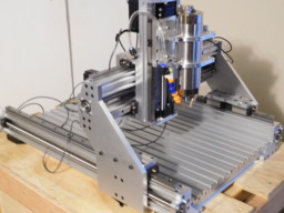
GRANITE 1.0

Discussion in 'CNC Mills/Routers' started by Michael.M, Sep 29, 2018.

  1. Michael.M

    Michael.M Veteran
    Staff Member Builder Resident Builder

    Joined:
    Jan 21, 2017
    Messages:
    432
    Likes Received:
    266
    From what I understand, it's the top of the sensor on the "X". They're nice and compact. 15441457768187543605866724642766.jpg
     
  2. CNCMD

    CNCMD Journeyman
    Builder

    Joined:
    Jul 29, 2017
    Messages:
    148
    Likes Received:
    115
    Well as usual keep us posted. Tonight I upgraded all my limit switches to much more beefy Temco Brand ones, that have an adjustable arm.

    The issues I was having was I was drilling and tapping the holes in them which was stressing the plastic and therefore causing the casing to crack and over time they were failing, one by one.
     
  3. CNCMD

    CNCMD Journeyman
    Builder

    Joined:
    Jul 29, 2017
    Messages:
    148
    Likes Received:
    115
    Here is what they look like.

    20181206_221732.jpg
     
    GrayUK and Michael.M like this.
  4. Michael.M

    Michael.M Veteran
    Staff Member Builder Resident Builder

    Joined:
    Jan 21, 2017
    Messages:
    432
    Likes Received:
    266
    Those are nice looking switches
     
  5. CNCMD

    CNCMD Journeyman
    Builder

    Joined:
    Jul 29, 2017
    Messages:
    148
    Likes Received:
    115
    Thanks, I'm very content with these. Very solid construction. $20 for 3 of them. All metal construction. I was able to mount them without any major modifications to the machine, and only lost a few mm in travel. The can be wired NO or NC. I'm running NC in the event a something goes bad.

    I honestly didn't want to have to run any additional wires.
     
    Michael.M likes this.
  6. GrayUK

    GrayUK Openbuilds Team Elder
    Staff Member Moderator Builder

    Joined:
    May 5, 2014
    Messages:
    1,668
    Likes Received:
    627
    They look very substantial. Nice find.
    I'll keep these in mind.
    Can you put a post/reference into the Resources section for these?
    Cheers
     
    CNCMD likes this.
  7. Michael.M

    Michael.M Veteran
    Staff Member Builder Resident Builder

    Joined:
    Jan 21, 2017
    Messages:
    432
    Likes Received:
    266
    I'm not sure if you're talking about the inductive sensors or the Temco switches but I'll add an eBay link to the sensors.
     
    GrayUK likes this.
  8. Michael.M

    Michael.M Veteran
    Staff Member Builder Resident Builder

    Joined:
    Jan 21, 2017
    Messages:
    432
    Likes Received:
    266
    So I did some testing and these sensors do trigger with aluminum. They have to be very close. I wanted to also say that anyone who uses these should make their "trigger" object so it passes over the top of the sensor as opposed to a trigger that would approach directly at the sensor. This is to prevent the machine from actually crashing in to the sensor during a fast move. Anyway, these little sensors are pretty slick and their almost completely protected from chips & coolant. There are a couple ways to install them but you just have to make sure and protect your controller. I will be using an inline diode. Hayri (Phoenix CNC controller designer) recommended these to me and the price is very affordable. DSCN2453.JPG DSCN2450.JPG DSCN2447.JPG
     
  9. GrayUK

    GrayUK Openbuilds Team Elder
    Staff Member Moderator Builder

    Joined:
    May 5, 2014
    Messages:
    1,668
    Likes Received:
    627
    Why an "inline diode"?
     
  10. Michael.M

    Michael.M Veteran
    Staff Member Builder Resident Builder

    Joined:
    Jan 21, 2017
    Messages:
    432
    Likes Received:
    266
    To allow safe operation of these switches @ 12-24v
     
    #130 Michael.M, Dec 9, 2018
    Last edited: Dec 9, 2018
    GrayUK likes this.
  11. Michael.M

    Michael.M Veteran
    Staff Member Builder Resident Builder

    Joined:
    Jan 21, 2017
    Messages:
    432
    Likes Received:
    266
    The switches operate just fine by themselves at that voltage range but my controller (essentially an Arduino uno) can't handle this voltage on this circuit. This is what Hayri recommended.
     
    GrayUK likes this.
  12. Michael.M

    Michael.M Veteran
    Staff Member Builder Resident Builder

    Joined:
    Jan 21, 2017
    Messages:
    432
    Likes Received:
    266
    PL-05N_switch_5.jpg
    These sensors have 3 wires. Here's the recommended Arduino UNO wiring diagram using the 1N4148 diode.
     
  13. CNCMD

    CNCMD Journeyman
    Builder

    Joined:
    Jul 29, 2017
    Messages:
    148
    Likes Received:
    115
    There is a multiplier for these sensors based on the metal type. For aluminum you multiply the base distance, 5mm by .04 = 2mm trigger for aluminum.
     
    GrayUK likes this.
  14. Michael.M

    Michael.M Veteran
    Staff Member Builder Resident Builder

    Joined:
    Jan 21, 2017
    Messages:
    432
    Likes Received:
    266
    Hey thanks dude. I plan on making these adjustable but I am wondering if aluminum chips can trigger the sensor. For the most part, my X and Y axis will be protected. I actually need to be working on protective covers for the Z axis rails.
     
  15. Michael.M

    Michael.M Veteran
    Staff Member Builder Resident Builder

    Joined:
    Jan 21, 2017
    Messages:
    432
    Likes Received:
    266
    So I was trying to figure out what it would take to install those red inductive sensors and they were actually going to require some teardown and modification of some parts. This is mainly because of the sensor detection area in relation to how they need to be mounted. I found a lower profile version of the same sensor on Amazon. They are more expensive but, at this point, I really don't want to tear this machine apart any more. I just decided to spend the money to avoid this. There are cheaper versions of this low profile sensor on eBay but they would be on the slow boat from China. Also, these new sensors have a detection area in a better location for my purpose. 15448823892472579483521541197322.jpg 15448826170175636430085058379082.jpg
     
    Pencoat likes this.
  16. Michael.M

    Michael.M Veteran
    Staff Member Builder Resident Builder

    Joined:
    Jan 21, 2017
    Messages:
    432
    Likes Received:
    266
  17. Michael.M

    Michael.M Veteran
    Staff Member Builder Resident Builder

    Joined:
    Jan 21, 2017
    Messages:
    432
    Likes Received:
    266
    Installed the limit sensors this weekend. Unfortunately I had to disassemble half the machine to make clearance for them. It's become a fair amount of work to do so I hope this is the last time I need to tear it down.
    DSCN2525.JPG DSCN2480.JPG DSCN2481.JPG DSCN2482.JPG DSCN2486.JPG DSCN2488.JPG DSCN2489.JPG DSCN2492.JPG DSCN2494.JPG DSCN2495.JPG DSCN2496.JPG DSCN2509.JPG DSCN2514.JPG DSCN2515.JPG
     
  18. Julius

    Julius Well-Known
    Builder

    Joined:
    Nov 13, 2015
    Messages:
    193
    Likes Received:
    61
    Beautiful build. Amazing linear block plates.
     
    Michael.M likes this.
  19. Michael.M

    Michael.M Veteran
    Staff Member Builder Resident Builder

    Joined:
    Jan 21, 2017
    Messages:
    432
    Likes Received:
    266
    Thank you Julius. Happy Holidays!
     
  20. CNCMD

    CNCMD Journeyman
    Builder

    Joined:
    Jul 29, 2017
    Messages:
    148
    Likes Received:
    115
    Nice work buddy! I had fun yesterday with full disassembly of my Z Axis. I made a new mounting plate so that I could get some additional clearance. My plan is to get a true 4" vise on the table and stop messing around lol.
     
    Michael.M likes this.
  21. Michael.M

    Michael.M Veteran
    Staff Member Builder Resident Builder

    Joined:
    Jan 21, 2017
    Messages:
    432
    Likes Received:
    266

    Awesome dude! I made my z axis back plate with a series of holes to allow for adjustment. How is that low profile milling vise working for you?
     
  22. CNCMD

    CNCMD Journeyman
    Builder

    Joined:
    Jul 29, 2017
    Messages:
    148
    Likes Received:
    115
    It's a decent low profile vise. I've been using it a good amount lately.
     
  23. Todd B

    Todd B New
    Builder

    Joined:
    Feb 11, 2019
    Messages:
    3
    Likes Received:
    0
    Hi Michael,
    One question: why did you choose to mount the guides on top of the Y-axis C-beam, as opposed to the outer sides? Rigidity, travel limits, assy?
    If the guides are mounted on the outer side of the Y-axis C-beam, the ball-screws would move out a bit, but also potentially save 2 parts. I think?

    Edit: Looking closer I may have a guess - the guide blocks would hit the ball screw? Please correct me.

    -Todd
     
    #143 Todd B, Feb 11, 2019
    Last edited: Feb 11, 2019
  24. Michael.M

    Michael.M Veteran
    Staff Member Builder Resident Builder

    Joined:
    Jan 21, 2017
    Messages:
    432
    Likes Received:
    266
    Hi Todd,
    So the machine design changed a couple times before I actually built it. I was trying to bring the centerline of the spindle back towards the center of the Y axis linear carriage blocks (which I didn't completely accomplish). So if you look at the X plate ,that the Z axis mounts to, you can see it rides very close to the extrusion behind it. If I had placed the X linear rail facing forward, the spindle and Z axis would be located with more "stickout". Also, the lower X axis is actually facing forward but it is stepped back from the upper extrusion to support what I mentioned above. It's a little hard for me to explain all of this but I think it will work out.
     
    Todd B likes this.
  25. HuguesP

    HuguesP Well-Known
    Builder

    Joined:
    Jan 14, 2018
    Messages:
    30
    Likes Received:
    44
    hello Michael i was wondering how this machine is going with the time, i feel like i need to build something and your machine seems a great source of inspiration!
     
    NeeqOne likes this.
  26. Elias Martinelli

    Builder

    Joined:
    Sep 25, 2019
    Messages:
    1
    Likes Received:
    0
    Help
    Do you have the CAD Files and Part list, I`m really impressed about this build and want to build it too!
     
  27. H@wk

    H@wk New
    Builder

    Joined:
    Oct 31, 2018
    Messages:
    13
    Likes Received:
    14
    I agree Elias. This is an awesome machine. Looking forward to the CAD files.
     
  28. Gabor Czvikovszky

    Builder

    Joined:
    Dec 5, 2020
    Messages:
    1
    Likes Received:
    0
    Hello Michael,
    Its a professional approach, I am sure it works precisely. If there is anything you would change for the next project please let me know. I am about to make a similar machine. Thanks for the support. Cheers Gabor
     
  29. micklen

    micklen New
    Builder

    Joined:
    Feb 17, 2016
    Messages:
    2
    Likes Received:
    0
    Really like this build! Looks very rigid. Have you cut aluminium with this machine?
    Wonder what the maximum working area and hight is?
    Planning to build my first CNC and think this one is what I´m looking for.
     
  30. nocturnalit

    Builder

    Joined:
    Jun 27, 2021
    Messages:
    3
    Likes Received:
    0
    What size are the extrusions on the X rail?
     

Share This Page

  1. This site uses cookies to help personalise content, tailor your experience and to keep you logged in if you register.
    By continuing to use this site, you are consenting to our use of cookies.
    Dismiss Notice