Welcome to Our Community

Some features disabled for guests. Register Today.

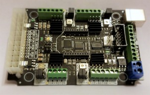
CNC xPRO Driver

Discussion in 'Other Builds' started by Spark Concepts, May 25, 2014.

  1. Rob Atha

    Rob Atha New
    Builder

    Joined:
    Aug 19, 2018
    Messages:
    53
    Likes Received:
    7
     
  2. Spark Concepts

    Spark Concepts Journeyman
    Builder

    Joined:
    Dec 17, 2013
    Messages:
    131
    Likes Received:
    107
    Hi @Rob Atha

    Glad to hear you like the V4, labor of love that one was...

    For your questions:

    1) the fan plug will match the raw input voltage, in your case 24V
    2) The Estop on the xPRO will cause cut the enable line to the drivers killing all power to the motors and will stop the firmware (most senders, not all, will pickup the Estop input and restart the firmware as well)
    3) we haven't worked with this spindle yet. Did they send you a wiring diagram? There is a spindle speed control ouput on the xPRO that can be either 0-5V or 0-10V output but we need to know where to put it ;).

    feel free to email us as well mike @spark-concepts.com

    Thanks,
    Mike
     
  3. Rob Atha

    Rob Atha New
    Builder

    Joined:
    Aug 19, 2018
    Messages:
    53
    Likes Received:
    7
    DD9CAC05-BAEC-4F0C-A7A6-DD1A3A175D04.jpeg DD9CAC05-BAEC-4F0C-A7A6-DD1A3A175D04.jpeg 1B6C04E9-E5D6-419A-8178-F4AD2B2A9125.jpeg 4C105A9B-2C5F-4DD3-A54F-C7FBD17C1CB9.jpeg
    Hi mike

    Sorry I don’t have a wiring diagram for the spindle motor, it was just a cheap spindle bought on eBay

    I do have a serious question/concern though. I left my machine running an 8 hour cut and came back to it to find the USB port had moved on the board, it looks like there is a serious problem with heat. M running a 24 volt system cooling fans are installed everywhere and as you can see from the photos I installed the xpro upside down to avoid stress on the port . I just wish I’d taken the photos before I tried to secure the port with epoxy.

    My problem now is it cost a fortune to have this shipped from the states so I’m now waiting for @ooznest to get stock or think about maybe getting a blue bee module

    Rob
     

    Attached Files:

  4. Spark Concepts

    Spark Concepts Journeyman
    Builder

    Joined:
    Dec 17, 2013
    Messages:
    131
    Likes Received:
    107
    @Rob Atha - probably not heat on that one, we did a lot of thermal testing on the V4 (72hr full current runs with no active cooling). The heat is generated from the motor drivers but they will go into thermal shutdown at 356 degrees farenheit and only come back on when they cool to operating temperature. For reference the usb plug requires a 700 degree iron for about 10 seconds to reflow. Hopefully gives you some peace of mind.

    However, interesting failure that I would like the techs to look at - how about a trade? Email me at mike @spark-concepts.com if you want to (take out the space)
     
    Rob Atha and GrayUK like this.
  5. Peter Van Der Walt

    Peter Van Der Walt OpenBuilds Team
    Staff Member Moderator Builder Resident Builder

    Joined:
    Mar 1, 2017
    Messages:
    14,917
    Likes Received:
    4,290
    Sounds similar to what @email.james.home reported at OpenBuilds CONTROL Software
    - just reporting as it might help track down an issue if a pattern emerges
     
    Rob Atha likes this.
  6. Rob Atha

    Rob Atha New
    Builder

    Joined:
    Aug 19, 2018
    Messages:
    53
    Likes Received:
    7
    Thanks Mike. I’ve sent you an email
     
    Spark Concepts likes this.
  7. Bob Waterfield

    Builder

    Joined:
    Jan 21, 2019
    Messages:
    21
    Likes Received:
    4
    Is there any external pendant or remote control board that is compatible with the CNC Ver4 board?
    I am currently using lightburn software, but it would be nice to have a separate display, control board that would eliminate most of the need to have a computer hooked up all the time.
     
  8. David Bunch

    David Bunch Veteran
    Builder

    Joined:
    Oct 27, 2014
    Messages:
    624
    Likes Received:
    432
    Is it possible to use the (D3) Z-Probe pin & GND connection for using the Z-Probe? The video I saw used a couple of pins in the 10 pin block just inside the board. I tried it with the D3 & GND and it times out for me. Seems like if it is marked Z-Probe for that pin, I should be able to use it. Do I need to map those pins somehow or should I just use those shown in the video. I finally found this page that shows what those connections in the video are: Spark-Concepts/xPRO It is shown under the xPro V1 pinout 3/4 the way down that page which maybe did not change for V3. From that diagram looks like A5 & GND he has connected to in the video.
     
  9. Spark Concepts

    Spark Concepts Journeyman
    Builder

    Joined:
    Dec 17, 2013
    Messages:
    131
    Likes Received:
    107
    Hi David, you can use the Z-probe pin, no changes needed. The time out has to do with the max travel you set in the probe command, just make that a little longer or start the bit closer to the probe
     
  10. David Bunch

    David Bunch Veteran
    Builder

    Joined:
    Oct 27, 2014
    Messages:
    624
    Likes Received:
    432
    Maybe I have some connection not right then since it hit the bottom the last time I did it. Is there a status command I can type while holding the connections together to verify whether it is triggered or not? Here is a photo of the way I hooked it up on the xPRO V3. Does this look like I have it on the correct pins?
    IMG_6660_800x600.jpg
     
  11. Gary Caruso

    Gary Caruso OpenBuilds Volunteer
    Staff Member Moderator Builder

    Joined:
    May 19, 2016
    Messages:
    1,193
    Likes Received:
    532
    D3 and ground should work (pin-outs pic here), what software are you using? most have a section to observe input status for testing.
    Another thing to consider is how you are wiring it to the probe plate and endmill, some spindles are insulated so they require direct clip onto the endmill, my Makita is like that.
    Cheers

    Gary
     
    Spark Concepts likes this.
  12. David Bunch

    David Bunch Veteran
    Builder

    Joined:
    Oct 27, 2014
    Messages:
    624
    Likes Received:
    432
    I am currently using the openbuilds control software. It apparently was the coating on the endmill. I tried running the G38.2 code & connected the 2 alligator clips together & it triggered. I then was more careful where to put the clip on the endmill & it worked that time. I also tried the A5 connector too while I was at it & that worked also. Thanks for the help.
     
  13. Mike Kulaczkowski

    Builder

    Joined:
    Apr 22, 2019
    Messages:
    2
    Likes Received:
    0
    @Spark Concepts I'm using xpro v4 on my cnc router and used to have problems with limit switches' false triggers. Found this image online which shows how to hook up an optocoupler to the proximity switches and all been good ever since, but I'm still having problems with false triggers when probing.

    Can someone explain how to connect simple two wire probe to the controller via the optocoupler?
     

    Attached Files:

  14. BatmiteSG

    BatmiteSG New
    Builder

    Joined:
    May 7, 2019
    Messages:
    2
    Likes Received:
    0
    Hi,

    I am facing some problems with my xPro V4. All is fine for the motion of my X/Y/Z, but I can't get my spindle to spin using the PWM port of the board.
    I am using a Huanyang VFD with a 2.2kW water cooled spindle.

    If I use external control from the VFD no problem, I can spin and modulate the speed.
    But whenever I tried from the xPro it starts spinning and stop within seconds. And on the console I have lots of line with "Grbl 1.1f ['$' for help]" displaying. The number of lines varies, and sometimes they are incomplete.

    Here under is the configuration of my board/machine and the log of what is tipically happening:

    Code:
    CNCjs 1.9.20 [Grbl]
    Connected to COM4 with a baud rate of 115200
    
    Grbl 1.1f ['$' for help]
    client> $$
    [MSG:'$H'|'$X' to unlock]
    $0=10 (Step pulse time, microseconds)
    $1=255 (Step idle delay, milliseconds)
    $2=0 (Step pulse invert, mask)
    $3=1 (Step direction invert, mask)
    $4=1 (Invert step enable pin, boolean)
    $5=0 (Invert limit pins, boolean)
    $6=0 (Invert probe pin, boolean)
    $10=3 (Status report options, mask)
    $11=0.020 (Junction deviation, millimeters)
    $12=0.002 (Arc tolerance, millimeters)
    $13=0 (Report in inches, boolean)
    $20=1 (Soft limits enable, boolean)
    $21=1 (Hard limits enable, boolean)
    $22=1 (Homing cycle enable, boolean)
    $23=0 (Homing direction invert, mask)
    $24=500.000 (Homing locate feed rate, mm/min)
    $25=1000.000 (Homing search seek rate, mm/min)
    $26=50 (Homing switch debounce delay, milliseconds)
    $27=5.000 (Homing switch pull-off distance, millimeters)
    $30=24000 (Maximum spindle speed, RPM)
    $31=2000 (Minimum spindle speed, RPM)
    $32=0 (Laser-mode enable, boolean)
    $100=320.000 (X-axis travel resolution, step/mm)
    $101=320.000 (Y-axis travel resolution, step/mm)
    $102=320.000 (Z-axis travel resolution, step/mm)
    $110=6000.000 (X-axis maximum rate, mm/min)
    $111=6000.000 (Y-axis maximum rate, mm/min)
    $112=6000.000 (Z-axis maximum rate, mm/min)
    $120=500.000 (X-axis acceleration, mm/sec^2)
    $121=500.000 (Y-axis acceleration, mm/sec^2)
    $122=500.000 (Z-axis acceleration, mm/sec^2)
    $130=650.000 (X-axis maximum travel, millimeters)
    $131=360.000 (Y-axis maximum travel, millimeters)
    $132=100.000 (Z-axis maximum travel, millimeters)
    ok
    client>
    Grbl 1.1f ['$' for help]
    [MSG:'$H'|'$X' to unlock]
    client> $X
    [MSG:Caution: Unlocked]
    ok
    feeder> M3 S3000
    ok
    Grbl 1.1f ['$' for help]
    Grbl 1.1f ['$' for help]
    Grbl 1.1f ['$' for help]
    Grbl 1.1f ['$' for help]
    Grbl 1.1f ['$' for help]
    Grbl 1.1f ['$' for help]
    Gr
    Grbl 1
    Grbl 1.1f ['$' for help]
    >
    The PWM goes to VI.
    The GND goes to ACM.
    And I have a wire to connect DCM and FOR.

    If I connect the 5v or 10v from the board to the VI no problem it spins fine at 200 or 400Hz.

    I am really clueless on the issue. Thanks in advance for any hints or help you could provide guys.

    Cheers
     
    #824 BatmiteSG, May 7, 2019
    Last edited: May 8, 2019
  15. Mike Kulaczkowski

    Builder

    Joined:
    Apr 22, 2019
    Messages:
    2
    Likes Received:
    0

    Such shame @Spark Concepts stopped replying to their own thread :/

    Had this happen to me multiple times. Grounding my machine solved the issue.
     
  16. BatmiteSG

    BatmiteSG New
    Builder

    Joined:
    May 7, 2019
    Messages:
    2
    Likes Received:
    0
    My problem was that not really grounding problem, that's properly done, but it's due to the proximity of my VFD with the xPro, which was just aside, and every time I powered up the VFD it did generate perturbations.
     
  17. deano

    deano New
    Builder

    Joined:
    Nov 9, 2016
    Messages:
    12
    Likes Received:
    1
    Hi, I'm new to writing on this forum, Thought have read lot's of useful information.
    Just wanted to ask a question,
    I have upgraded my CNC, now I have more powerful stepper motors, Nema 23 Stepper Motor 3Nm 4.2A.
    Also I have purchased DM542T 1-4.2A 20-50V DC Digital Stepper Motor Driver,
    I just wanted to know if this is a good idea and how to wire them up?
    And if I need something else to connect the Digital Stepper Motor Driver to my XPRO v3
    and if I need another power supply as i'm running on 24v ?
    Thanks for your help,
    Cheer's, Dean.
     
  18. Peter Van Der Walt

    Peter Van Der Walt OpenBuilds Team
    Staff Member Moderator Builder Resident Builder

    Joined:
    Mar 1, 2017
    Messages:
    14,917
    Likes Received:
    4,290
    See Hooking Up External Drivers to the CNC xPRO V3
     
  19. deano

    deano New
    Builder

    Joined:
    Nov 9, 2016
    Messages:
    12
    Likes Received:
    1
    Peter Van Der Walt likes this.
  20. deano

    deano New
    Builder

    Joined:
    Nov 9, 2016
    Messages:
    12
    Likes Received:
    1
    Hi Peter, I would like to know what power supply is recommended for stepper motor driver;s, 24v or 36v ect ?
    Also the diagram does not have the clone A axis,
    I have made a diagram just wanted you to see if this looks right, Thanks Dean.
     

    Attached Files:

  21. Peter Van Der Walt

    Peter Van Der Walt OpenBuilds Team
    Staff Member Moderator Builder Resident Builder

    Joined:
    Mar 1, 2017
    Messages:
    14,917
    Likes Received:
    4,290
    PSU voltage: Higher is always better, those are some beefy motors...

    Hard to see on the pic, its been resized, so cant check the pinouts too closely, but A should just have its step/dir wires paralleled to the axis you want to slave off.
     
  22. Giarc

    Giarc OpenBuilds Team
    Staff Member Moderator Builder Resident Builder

    Joined:
    Jan 24, 2015
    Messages:
    3,008
    Likes Received:
    1,676
    A 36 V drives my dq542ma drivers real nicely. The motors do not get hot at all.
     
  23. deano

    deano New
    Builder

    Joined:
    Nov 9, 2016
    Messages:
    12
    Likes Received:
    1
    Hi, Thanks again for the help you have given me,

    I have wired up my DM542T stepper motor drivers as like in the link you provided,

    Though now when I connect to UGS and try to nudge my motors they make a nasty crunching sound when they try to move?

    I only have a 24v power supply LRS-350-24V (I will upgrade to a 36V-10A-360W.)

    Also it could be, took me a while to figure out in the past, getting the stepper motor’s wire’s the right way round, Red, Green, Yellow, Blue. (A+ A- B+ B-)

    Lastly, I'm not sure what settings the stepper motor drivers should be on SW1 – SW8, On - Off, ect.

    Any advise would be great,

    Thanks, Dean.
     
  24. deano

    deano New
    Builder

    Joined:
    Nov 9, 2016
    Messages:
    12
    Likes Received:
    1
    Ok, I have been playing with the different combinations when wiring the motors! X, Z Axis is happy with A,B,C,D. Red, Blue, Green, Yellow.
    But the problem I am having is, the Y axis is wired, Red, Blue, Green, Yellow,
    But clone/slave Y is moving in opposite direction when I wired the same,
    If tried wiring clone/slave Y Axis, A, B, C, D, C, D, A, B, B, A, C, D, A, B, D, C, Move's in opposite Direction,
    Any other combination I Will hear a crunch from Motor!
    So frustrating! Any advice would be great! Thanks as always with help!
    Cheers.
     
  25. Peter Van Der Walt

    Peter Van Der Walt OpenBuilds Team
    Staff Member Moderator Builder Resident Builder

    Joined:
    Mar 1, 2017
    Messages:
    14,917
    Likes Received:
    4,290
    If Y axis is wired, Red, Blue, Green, Yellow,
    Then Slave Y should be Red, Blue, Yellow, Green (Swop the last two wires with each other)

    If it rattles, it could also be a loose connection (only 2/3 of the 4 wires have proper connection)
     
  26. Gary Caruso

    Gary Caruso OpenBuilds Volunteer
    Staff Member Moderator Builder

    Joined:
    May 19, 2016
    Messages:
    1,193
    Likes Received:
    532
    Check the wires for sure as Peter said, if still not moving smoothly set your switches for 1600 micro steps (1/8 microstep) and a current setting just below the rating of the motor.
    Cheers
    Gary
     
  27. Apeli

    Apeli New
    Builder

    Joined:
    Feb 15, 2018
    Messages:
    30
    Likes Received:
    12
    I'm having issues with limit switches and the xPro v4. When I trigger the switch, a red led lights up on the xPro board, but the machine won't stop moving. There also are not any error messages etc popping up on the Openbuilds Control software (or CNCjs which I tried before).
     
  28. Critical

    Critical New
    Builder

    Joined:
    Feb 9, 2017
    Messages:
    28
    Likes Received:
    14
    This lends itself well to Software, send $$ to your xPro and let us know what the values are :thumbsup:
     
    Peter Van Der Walt likes this.
  29. Peter Van Der Walt

    Peter Van Der Walt OpenBuilds Team
    Staff Member Moderator Builder Resident Builder

    Joined:
    Mar 1, 2017
    Messages:
    14,917
    Likes Received:
    4,290
    Check gnea/grbl (And when Hard limits is enabled, its also prudent to check $22-$27 if you want to Home as well, and if you have Hard Limits and Homing working, may as well check $20, $130-132 as well (so Soft Limits can take care of the other side of the axis if you only have switches on one side)

    Also read gnea/grbl
     
  30. Apeli

    Apeli New
    Builder

    Joined:
    Feb 15, 2018
    Messages:
    30
    Likes Received:
    12
    Thanks, will check when I get home. Most probably $21=0. I had the assumption that the limit switches are on by default but it seems that I was wrong about that.
     

Share This Page

  1. This site uses cookies to help personalise content, tailor your experience and to keep you logged in if you register.
    By continuing to use this site, you are consenting to our use of cookies.
    Dismiss Notice