Welcome to Our Community

Some features disabled for guests. Register Today.

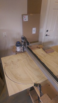
myOX : a 4' x 2' OX with potential

Discussion in 'CNC Mills/Routers' started by Serge E., Jun 19, 2014.

  1. Robert Hummel

    Robert Hummel Custom Builder
    Moderator

    Joined:
    Nov 14, 2013
    Messages:
    978
    Likes Received:
    715
    Turn down the current to the Nema 17 if that's the one giving noise if all the current is set the same you may be over driving the 17
     
  2. Serge E.

    Serge E. Journeyman
    Builder

    Joined:
    May 6, 2014
    Messages:
    730
    Likes Received:
    252
    Thanks, the Z seemed to get a bit warm while the others remain room temperature, considering I'm not running them for hours non stop. Z is not making any noise, moves nice and smooth, just a bit warm.

    This also points me to maybe an issue with the noisy Y stepper: is it underpowered ? It's way at the other end of the X 1500 mm length, using solid wire (it does not move, passes though X beam) instead of twisted wire compared to the other Y which is only inches away from the controller/driver. The driver current adjustment is about mid-point. Could that be border line for NEMA 23s ?
     
  3. Robert Hummel

    Robert Hummel Custom Builder
    Moderator

    Joined:
    Nov 14, 2013
    Messages:
    978
    Likes Received:
    715
    If your Nema 23 are from open builds they are rated for 2.8 amps where the Nema 17 are 1.8
    I would say crank up the current another 1/4 turn.
    Under or over powering can cause noise
     
    Serge E. likes this.
  4. Paruk

    Paruk Journeyman
    Builder

    Joined:
    Jul 13, 2014
    Messages:
    397
    Likes Received:
    149
    Hope this picture will make it clear to you why your X should be square with the Y and why 1/2 inch difference between right and left can cause a lot of noise. After this you're on your own as far as I'm concerned.
    Screen Shot 2014-10-11 at 14.09.16.png

    I think the sound is mostly coming from the friction of wheels on the profile, metal that gets twisted and rubbing against each other in combination with stepper motors working like hell to get the thing running.
    Keep going like this and sure something will break soon. Just my opinion.
     
    #124 Paruk, Oct 11, 2014
    Last edited: Oct 11, 2014
  5. Serge E.

    Serge E. Journeyman
    Builder

    Joined:
    May 6, 2014
    Messages:
    730
    Likes Received:
    252
    Thanks. I was suspecting something like that given the mechanics was getting pretty good (at least for me).

    The alternative was that I had damaged the one stepper (initial mis wiring) and/or, worse, the respective driver.
     
  6. Serge E.

    Serge E. Journeyman
    Builder

    Joined:
    May 6, 2014
    Messages:
    730
    Likes Received:
    252
    Like they say, a picture is worth a 1000 words. The only problem is your picture is not what I've been trying to explain in my Frenglish and limited technical jargon. Sorry for the confusion. So, still without a picture, but fewer words than my previous posts, I'll try again.

    The part you are missing is I always referred to, as best as, the two BASE 20x40 not the three 20x60 of the actual X beam, ones you illustrated. Of course, the latter needs to be squared to the rails they ride on (the Y beams). However, that's not my problem.

    What I obviously did not explain clearly, is that squaring the Ys with the BASE 20x40 (not the X carriage assembly, as shown in your sketch) is, at least in my situation, the worse thing I can do. This is due to fact that both sets of opposing sides are NOT quite equal in length (I should of measured and adjusted ALL lengths - the ones I cut AND the factory cut lengths, BEFORE the assembly process.

    Think of building a cabinet frame, a table base (legs+frame) or a perfect cube. Measuring the diagonals is a MUST to square the shape as the opposite sides must also be of equal length. But this squareness does very little for aligning the doors or the table top (yes, it helps if reference point is the frame, but most of the time that frame ends up out of sight and alignement of doors is done with respect of all other doors, etc.)

    Now think of a set of railroad tracks or the tracks of a roller coaster. As long as these rails being rode on (our Y) are parallel, does it really matter if the spacer beams (railroad ties) are of exact equal length or even dead on parallel with each other, the first to the very last thousands of feet or even miles away ? In fact, especially with roller coasters, those 'spacers' holding the rails equidistant form each other (ie parallel) can and do get into sometimes weird shapes and angles.


    This is my situation : to try and square the BASE (the two 20x40 with the 20x80 Ys, which together form the base frame of an OX, including myOX) is not as useful as one might be lead to think. Yet, as shown in one of the videos, "squaring" is shown as forcing two opposite corners of the BASE to make IT square. What MUST be SQUARED is EXACTLY what your sketch show : it is the X carriage/assembly to the two Y support beams.

    As such, we are both right BUT talking about two very different aspects of these builds. Sorry for the mass confusion possibly caused by my Frenglish and limited technical jargon.

    By not getting OCD about the squareness of the BASE, I managed to get the important X carriage/assembly to Y beam nice & square. In fact, I had it from the beginning and this was not the source of my problem.

    My problem, as might of been confirmed in other recent posts, is that I'm running my steppers slightly (or a lot) underpower (at least for X and Y steppers). The Z is most likely overpowered. Again, I am using the default factory setting of the controller as it was set mid-point (ie. seemingly "safe").

    Hope this little back and forth discussion helps others as well. Next time, I'll try to include a sketch. Sorry.
     
  7. Paruk

    Paruk Journeyman
    Builder

    Joined:
    Jul 13, 2014
    Messages:
    397
    Likes Received:
    149
    Well, whatever. Something is twisted, that's clear.
     
  8. GrayUK

    GrayUK Openbuilds Team Elder
    Staff Member Moderator Builder

    Joined:
    May 5, 2014
    Messages:
    1,668
    Likes Received:
    627
    If I may impose here, because it's getting boring. :)

    What Serge is saying, to paraphrase;

    "My Y's are parallel. :thumbsup:
    My X is Square to my Y's. :thumbsup:
    The Y's are, simply, not the same length." :thumbsup:

    That's it really, as far as I can see, and it has no bearing on the performance of the machine! :thumbsup:

    Gray
     
    Serge E. likes this.
  9. Serge E.

    Serge E. Journeyman
    Builder

    Joined:
    May 6, 2014
    Messages:
    730
    Likes Received:
    252
    Thanks. You make it look/sound so easy. :duh:

    You forgot "one of my Y stepper is noisy". It's probably since underpowered which most likely also explains the slight "bounce" when coming to our pulling out of a "rest/long pause" (stepper not having enough torque to keep its position ?)

    Now back to our regular programming ... let's get some chips flying off a chunk of wood (or plexiglass) !
     
  10. Serge E.

    Serge E. Journeyman
    Builder

    Joined:
    May 6, 2014
    Messages:
    730
    Likes Received:
    252
    Having figured the default current setting of the CNC xPro might not be ideal for MY steppers (not from OpenBuilds), I will be boosting current for the NEMA 23s (X and both Y) and turning down current for the lone NEMA 17 (Z). Also time to install the fans and such.

    First useful project for myOX : redo the plexiglass shields, complete with openings for control switches, displays (!), fan(s), etc.
     
  11. Serge E.

    Serge E. Journeyman
    Builder

    Joined:
    May 6, 2014
    Messages:
    730
    Likes Received:
    252
    I am also thinking about removing the two shorter pieces of 20x40, used to keep the two longer BASE 20x40 nicely parted.

    The two longer runs are fixed to the bench/table top using four "L" (double hole) brackets. I will be adding a couple straight brackets on the back side, it's flush with the bench/table back edge. That should be plenty, right ? The table is all wood, this might move a bit with time ? However, since the two shorter length of the base are already cut, might as well use them... just beyond working area / reach of the router.

    The thought is this will make for a clear path full width of the working area/volume. The spoiler board would sit down unto bench/table top. Spoiler could be a piece of 3/4 MDF (or higher density) for a nice flat work surface. This gives a 40 mm of extra working depth (Z). Spoiler would be held firmly in place with a few "L" brackets.

    A few passes of a wide tool bit to make the spoiler's surface perfect in relation to the working end of the bits and I could have that spoiler worn down towards ... say ... 1/2" thick as I clean any serious gouging done when cutting through work pieces.

    This full working area spoiler board would be removed to work pieces held beneath the table surface - myOX going deep once ready for this feat. That will be the introduction of the 4th axis ... manual at first, probably 4 positions : 90 degree rotation of work piece with a program/gCode for each of the four faces. With the right bit, seen some as long as 6.5", myOX, if Z is sturdy enough, should be able to work at least 4.5" deep into each face (using just the tool length) and maybe towards 6" if collet will not get into the way of the work piece. Deeper still if the Z assembly and router body won't get in the way... Work piece itself could be as thick as ... 24+" (resting down towards bottom of bench). Working volume would be a good 23" x 23" x 23"! Depth (Z) is limited by the bench height (currently about 30" in my case) minus a few inches. The width (X) is only limited by hole in bench/table top (currently shy of 24" but could be made the full cutting width of the router's reach ~ 48+" !) Front-back travel (Y) is limited by the table dimensions. However, if the work piece is held below the bench/table top frame, it could be infinity, just slide the work piece through between the top and bottom of the bench/table to work sections of about 20" or so at a time!

    Eager to get going making chips ... even if just some basic engraving for now.
     
  12. Serge E.

    Serge E. Journeyman
    Builder

    Joined:
    May 6, 2014
    Messages:
    730
    Likes Received:
    252
    Robert's suggestion of giving a bit more juice to the NEMA 23s (1/4 turn) worked wonders - steppers are quiet !

    Almost there, eh ? Well not quite, I noticed the two set screws on the near Y stepper were not quite tight enough, actually loose ! Tightening them was near impossible. So I replaced with what I had on hand from an other project : 16 mm long set screws. The difference was unbelievable. So I changed the ones on the other Y stepper as well. The X already had one of these since original is missing from package, so I changed the second as well. The new ones are long, but not in the way of anything. :thumbsup:

    I'll get some Loc-Tite (blue) to minimize risk of seeing any of them work their way loose. :thumbsup:

    Almost there, right ? Not quite, I now see some "stuttering" when moving Y ! Turns out the weak current and loose set screws had hidden a more troubling fact. There is a lack of squareness, as Prauk was trying to point out, but it's not were either him or myself OCDed about in the last few posts.

    So I spend a few hours over the weekend measuring and doing some actual routing (to put some resistance/load in the movements).

    My two Y beams are as parallel as I can measure : same distance apart all along their 750mm or so length AND diagonals are equal, given precision of a tape measure to span the 1500 mm or so distance. Precision is thus only about 1/32" (0.7938 mm). We've seen better.

    The two Y gantry plates seem as parallel to the Y beams as I can measure, using both old and new square. Not an evident measure. They also seem parallel to each other, doing same measurement as with Y beams, taking three different measurements : centre top, centre back and centre slopped front. :thumbsup:

    So where can the problem be ?! :banghead:

    Turns out, as I had mentioned and ignored earlier, the twinned X beams are NOT square to the Y plates... As I more precisely took measurements, using the new graduated square (30 cm long) and my trusted metal ruler, there is ~3.5 mm difference 30 cm out ... opposite end of the 1500 mm (or so) length the difference is just about the same in the opposite direction. This says, although both gantry plates are parallel, they are skewed ! Guess what ? ~3.5 mm over 300 mm gives ~17.5 mm over 1500 mm and that's by how much my near Y stops shorts of the far Y, having done all the other adjustments (down from a couple of inches mentioned early on)

    In other words, looking from either Y plate, the X beam goes "slightly" right. That "slight", after 1500 mm or so becomes ~17.5 mm ! Where I was aiming for the moon, I would be way way way off ... :jawdrop:

    o_O So it comes down to the "1500 mm" pre-cut length not all being "1500 mm". In fact, in measuring the twinned 20x60 and spare 20x40, they vary from 1504 to 1505 mm. As best I can measure the third X beam without taking everything apart, it sits at 1504.5 !

    This sort of situation does not seem to surface WHEN the OX is not using full factory cut length in the X axis, which seems to be the case for majority of builds seen to date (not that I look at every single one).

    So my idea of minimizing cuts by using full length pre-cut at the factory was NOT a good idea, especially blindly trusting they would come out perfectly "1500 mm". So far, all of the lengths I received are closer to 1505 mm (bad) then 1500 mm, none shorter (good).

    Measure ALL your V-slot lengths, pre-cut or home cut ! The error is mine, not measuring, not the factory, they do large batches and guarantee only the minimum length (by going a bit over spec'ed length).

    I now have to separate the Y plates from the 3 lengths of 20x60 (X axis beams) do one of two things :
    1. see if I can be lucky by just reordering the 3 lengths to have the slight difference in lengths work for me instead of against me
    2. or MAKE the three of equal length ... as in doing a precision cut (I have plenty of spare to still keep target 48" working width)
    The second is what I should of done in the first place ! So back to square one, no pun intended :blackeye:

    The trick here is to make a perfect square cut ! :nailbite: My experience with splitting the 20x80 1500mm length in two "equal" pieces is memorable, a hand mitre saw, at least in my hands, is not the ideal tool for the required level of precision. I will need to get a finely tuned chop saw / mitre saw along with an appropriate blade to do the job right in no time. Would of saved me (and you) from a lot aggravation / posts. :oops:

    Off to the store I go once again... Looking at this from a positive point of view : I needed a nice mitre saw for the longest of time. :duh: Let's hope the gods of sales are with me so I don't end up spending a bundle on this. Oh, this time, I won't bring the wife along. The previous trip for a few end mills ended up with two new coats (ok, one is for me), shoes, etc. BUT not a single tool ! It would of paid that mitre saw at least once over ... :zipit:
     
  13. DiggerJ

    DiggerJ Journeyman
    Builder

    Joined:
    Sep 2, 2014
    Messages:
    412
    Likes Received:
    109
    Make sure you do some research. Some of he miter saws that look good, cut like cr@p!
    Might as well go for the sliding compound miter saw and only bleed once. I had a decent miter saw and gave it to a friend who was wanting to do some woodworking. Gave me a reason to buy a new saw.

    Please remember the proper protective gear. The aluminum flecks will fly. Blind CNC would prolly not be any fun!
     
  14. Paruk

    Paruk Journeyman
    Builder

    Joined:
    Jul 13, 2014
    Messages:
    397
    Likes Received:
    149
    Sorry to say, but a sliding compound miter saw might look good, but is less accurate than a good quality miter saw (the ones without the sliding!). The sliding system makes them less accurate and as one can see, even 0.1mm off on a miter cut can cause a lot of problems. ;)
     
  15. DiggerJ

    DiggerJ Journeyman
    Builder

    Joined:
    Sep 2, 2014
    Messages:
    412
    Likes Received:
    109
    I guess I'm lucky. I used my TS to cut mine, and it is dead nuts on. I cut some with my SCMS and chopsaw and both measure the same. To be honest, I only chopped using the slider, (no slid), and my saw is very tight and new.

    You are correct, it can get more out of whack, but I use it mostly for woodworking where I seldom need sub-mm accuracy.

    I believe in keeping my saws adjusted as a regular part of upkeep. I was only suggesting the SCMS if you are only using it for a bit of aluminum and then for woodworking.
     
  16. Serge E.

    Serge E. Journeyman
    Builder

    Joined:
    May 6, 2014
    Messages:
    730
    Likes Received:
    252
    Definitely, I'll go for the best I can afford as it will be a long term investment.

    Safety gear is a must, especially when cutting such material ... I was going to use the old Shop Smith, but thought ... wait ... like a table saw, it tends to throw dust and chips right at operator even with the vacuum on. I'm not eager to get aluminum chips thrown at me !!! Not to forget the sharp chips all over the garage floor - not good for the car's tires.

    It's moment like this I wish I had kept my dad's huge shop vacuum system and some of the other tools. :oops:

    Talking safety, I'm thinking of doing some sort of front operator shield for myOX as well. While doing some test runs I cut a little deep with the engraving, the material I'm using is a bit thin, a piece was cut right through and pushed away (but not flying too far though).
     
  17. Serge E.

    Serge E. Journeyman
    Builder

    Joined:
    May 6, 2014
    Messages:
    730
    Likes Received:
    252
    Thanks for the heads up. Should I just go for a good chop saw then ? Keep it for cutting the aluminum and metals. I have the old Shop Smith for cutting wood, which I am not doing much of lately ... I won't have to change blades between jobs either.
     
  18. Serge E.

    Serge E. Journeyman
    Builder

    Joined:
    May 6, 2014
    Messages:
    730
    Likes Received:
    252
    Out of curiosity, which SCMS and chop saws are you using ? As reference for my shopping spree ...
     
  19. Paruk

    Paruk Journeyman
    Builder

    Joined:
    Jul 13, 2014
    Messages:
    397
    Likes Received:
    149
    Digger, you're dead on with you comments about the miter saws. Couldn't have said it better. I use mine also mainly for woodwork with monthly maintenance and fine adjustments. It's pretty accurate, but with sliding it gets a bit wobbly. Just a bit, hardly noticeable but still. It's a good one though, a Makita Ls1016 with laser (although I hardly use it for precision work).

    If you want to have your cut dead on, stick tape over the slot below the saw blade, cut it carefully once and you have a perfect marker for consecutive cuts.
     
  20. DiggerJ

    DiggerJ Journeyman
    Builder

    Joined:
    Sep 2, 2014
    Messages:
    412
    Likes Received:
    109
    My wood miter saw was an old heavy iron Delta. No fancy features, but adjusted well, cut very true. I gave it to a friend to entice him into woodworking.

    My SCMS is a 12" Hitachi Dual bevel SCMS. Better warranty than many, and I saw first hand use from a few contractor woodworker friends, I liked the feel better than any other saws I tried. YMMV
    It come with a pretty nice laser line system. Not fine enough for sub-mm tolerances, but plenty good for my woodworking projects.
     
  21. DiggerJ

    DiggerJ Journeyman
    Builder

    Joined:
    Sep 2, 2014
    Messages:
    412
    Likes Received:
    109
    Yeah, dust collection is nice. I have a 2hp 2-stage unit I built with a Thein separator that I built, that funnels the chips into a 55 gallon barrel. My collection bag stays almost empty and the debris never touches the impellor. Whole thing cost about $225.00.

    Are you using a dust shoe on your CNC setup? I would think that would keep most of the crud down.
     
  22. Paruk

    Paruk Journeyman
    Builder

    Joined:
    Jul 13, 2014
    Messages:
    397
    Likes Received:
    149
    Yeah the Hitachi's are pretty good. At the time they didn't have them here in Thailand so I choose for Makita. Next time I probably would go for the Hitachi, seems to be more sturdy than the Makita.

    I' m building a separate room for the CNC woodwork. It will have a central dust extraction to suck out airborne particles and a dust shoe on the router itself. That should keep most of it under control. Also build a Thein separator for on top of a blue LDPE barrel of 55 gal. That is connected to a 3HP industrial type vacuum cleaner. Hopefully it can serve the whole workshop, including the CNC room with 4" pipes and hoses.
     
  23. DiggerJ

    DiggerJ Journeyman
    Builder

    Joined:
    Sep 2, 2014
    Messages:
    412
    Likes Received:
    109
    That should work fine. I will try to find the pics of my DC setup. It works very well and allows me to use the enclosure to store clamps, tools, whiteboard for doodling etc. Getting ready to put an air compressor on top of it to save more space.

    Found them:
    http://lumberjocks.com/DiggerJ/blog/41561
     
  24. Paruk

    Paruk Journeyman
    Builder

    Joined:
    Jul 13, 2014
    Messages:
    397
    Likes Received:
    149
    This is my workshop, still under construction though, but it gives an idea. Dimensions about 20x8 meter, effective workspace about 7.5x10 meter.
    workshop 2.jpg workshop.jpg
     
  25. DiggerJ

    DiggerJ Journeyman
    Builder

    Joined:
    Sep 2, 2014
    Messages:
    412
    Likes Received:
    109
    That should work. Wish we had the weather to support that kind of structure.
     
  26. Paruk

    Paruk Journeyman
    Builder

    Joined:
    Jul 13, 2014
    Messages:
    397
    Likes Received:
    149
    This kind of construction is extremely strong, certainly if you use an inner and outer shell. The form can withstand very high wind speeds, but make sure no wind enters the building because it will act as a funnel and blow your wig off! (and the roof plates possibly).;)
     
  27. Serge E.

    Serge E. Journeyman
    Builder

    Joined:
    May 6, 2014
    Messages:
    730
    Likes Received:
    252
    Well, plenty to think about for precision cuts of extrusion ...

    I certainly don't have the room for a shop like either of yours (Prauk or DiggerJ), so I have to keep things compact.
     
  28. Serge E.

    Serge E. Journeyman
    Builder

    Joined:
    May 6, 2014
    Messages:
    730
    Likes Received:
    252
    In looking at various mitre saws to cut both the aluminum extrusions and, more frequently for now, other materials, namely wood, what are your thoughts on this the Evolution Rage3 Multi-Purpose Sliding Mitre Saw ?

    CanadianTire has it now on special for 280$cnd, while HomeDepot.com (US) has it for 300$us along with the double bevel version for an extra 100$us.

    Here's a YouTube of it as well as the Evolution YouTube. An 'unbiased' video review. They've been around, at least in Europe, for a few years now ...

    The part that is catching my inexperienced eye, the better one of the two I have, is that the RPM is 2500, versus the 4000 to 5000 RPM of the 'regular' mitre saws. The latter being always highlighted as being much too high to cut aluminum or anything other than wood or requiring blades with a high tooth count, for non-ferrous material, etc. which, for the most part, seem to cost double if not more then an Evolution blade. Tricks to use with regular mitre saws include flipping the blade (gives negative angle to teeth cutting edge) and to some how reduce the RPM (extra cost).

    The Rage3 has a 2000 watt soft start 15 amp motor, 1 inch arbor and cut capacity of 300mm x 80mm to boot. Seems plenty for me ...

    "Utilising patented professional RAGEĀ® technology; easily cuts Steel, Aluminium, Wood (even wood with nails) and Plastic, using just one blade ! Features a hi-torque gearbox, which reduces motor stresses, improving performance and durability."

    "Advanced performance; out performs normal saws. When cutting Steel, it leaves an instantly workable finish, producing no heat, no burr and virtually no sparks - unlike alternative methods."

    "... include a robust outer casing which enhances durability on even the most demanding metallic applications"

    Since it can cut through steel rebar, cutting aluminum profiles should be a walk in the park (they don't specify maximum thickness for aluminum cuts). Blades seem to last quite a while, over 700 cuts through steel (can't find the link ... maybe it was in PDF of manual).

    It seems relatively easy to adjust for precision (squared) cuts. Regular maintenance, as with any tool, being key. The changing blades seems real easy as well, compared to some saws I had to use to date.

    The one catch might be the part about having to use their blades, designed for this mitre saw. They have their multipurpose blade - a TCT to "cut : mild steel, aluminium, wood with nails, plastics and much more"; a diamond version to "cut : brick, concrete, ceramics, limestone, marble, natural stone, porcelain, slate tiles and much more"; and a third just to cut wood. The multi purpose blade can be found on Amazon.ca for about 40$cnd (Amazon.com has it for 34.50$us)

    They are still around after at least 4 years in Europe (England mostly from the links found to date), so getting blades should be safe ...

    It certainly seems to be a good choice for a guy like me : little room to spare, occasional need to cut various materials, budget minded.

    What about precision ? Squareness is the most critical, especially for projects like ours. Being able to repeat precise length as well. I might go for it (special is on just for a couple of weeks and they might go fast if they are as good as they claim). I can always return the unopened box ... even opened if there is a problem and little use.

    Would like to hear your thoughts ...
     
  29. GrayUK

    GrayUK Openbuilds Team Elder
    Staff Member Moderator Builder

    Joined:
    May 5, 2014
    Messages:
    1,668
    Likes Received:
    627
    Hi Serge.
    I've had an Evolution Rage 3 for about a year now, and still use the same, multi-material, blade that came with it. It has no problem with cutting aluminium, and obviously wood, but I've not tried steel. :thumbsup:
    Points of interest:
    You seriously need to use ear defenders when cutting Aluminium! It hits that painful note! :jawdrop:
    I always use a set square to set up the square of the blade. Whilst the preset is almost right, sometimes it benefits from that extra bit of precision. :cool:
    As I'm sure you realise, it is really important to let the blade eat its way through the metal. No pushing if you want accuracy! :rolleyes:
    Clamp the metal down. Don't rely on holding it in place by hand. The aluminium we deal with is too expensive to let slip and have to re-cut all the others to match. Plus you may need your fingers for another job sometime. :eek:
    And most important of all, take your time.

    I'm sure you are aware of all those points, and I'm sorry if I'm trying to teach you to suck eggs, but Yes, I'd go for the Rage if I were you. :thumbsup::thumbsup:

    Cheers
    Gray
     
  30. Paruk

    Paruk Journeyman
    Builder

    Joined:
    Jul 13, 2014
    Messages:
    397
    Likes Received:
    149
    Very interesting product and the price is not too crazy. I would go for some extra blades at purchase so if they do go belly up at least you can last some time with the machine. Also check if the machine has enough possibilities to adjust for squareness in all directions. If not, let it be. When it goes out of square for some reason, there is no way to adjust it.

    For example: I have a Makita MLT100 contractors saw. As most of them, there is no way to adjust it for parallel with the miter slots once it left the factory or any other kind of needed adjustments. So if it is off, it will stay off. Unless (like me) you take it apart, understand the construction and the way it works, and redo the job that actually should have been done at Makita. My MLT100 is now perfectly square in all directions and every cut is a precision cut with less than 0.01 play.

    This Evolution is clearly a contractors tool and they don't need the accuracy that you need for the profiles to cut. So if you buy it there is a job to do on your brand new saw. Spent the time to get it perfectly accurate and you will have a lot of good and perfect cuts out of it. Don't be afraid to take it apart if necessary (except for the electrical) to get it right.

    Good luck with it.
     

Share This Page

  1. This site uses cookies to help personalise content, tailor your experience and to keep you logged in if you register.
    By continuing to use this site, you are consenting to our use of cookies.
    Dismiss Notice