Welcome to Our Community

Some features disabled for guests. Register Today.

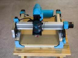
Sphinx 55 with 3D Printed Addons

Discussion in 'CNC Mills/Routers' started by David Bunch, Nov 28, 2018.

  1. David Bunch

    David Bunch Veteran
    Builder

    Joined:
    Oct 27, 2014
    Messages:
    624
    Likes Received:
    432
    Here is a video of less than 2 minutes showing some of that cutting. I took out a lot of the footage, since it is mostly the same throughout the video.
     
  2. David Bunch

    David Bunch Veteran
    Builder

    Joined:
    Oct 27, 2014
    Messages:
    624
    Likes Received:
    432
    I found another spot to control dust. After my last cut, I noticed a lot of dust on the wiring in the back & came up with this slanted wall that should keep most of the dust out of there.
    IMG_6786_800x600.jpg IMG_6792_800x600.jpg
    I also finished the dust boot that attaches to the router & updated the thingiverse design for this & included the fusion 360 file. Remix of Bosch Colt Dust Boot to make one part by GeoDave
    IMG_6793_800x600.jpg IMG_6795_800x600.jpg
    After getting this done, his morning I had an idea of how to make that stable dust boot that would attach to the bottom C-Beam mount & seems like it should work. I will print it tomorrow with some inexpensive PLA to test it. Here are a couple of screen captures of the idea. I initially made 2 versions with a detachable side support & combined support. I am going with the combined side support to start with.
    BottomStableDustBootMountLeft.JPG BottomStableDustBoot_Slicer.JPG
     
  3. David Bunch

    David Bunch Veteran
    Builder

    Joined:
    Oct 27, 2014
    Messages:
    624
    Likes Received:
    432
    I did my test fit today. I printed this at .3mm layer height for faster print & it only took about 3 hours. A couple things I noticed, which one was very important. My tool mount was not quite centered. I will have to make a plastic jig to make sure it is pretty close to centered. I changed the design some today, making the hole for the router opening 44mm OD, instead of 30mm so the router can go further down if need be. Also the inside diameter of this boot where the router fits was a little tight, so I added 2mm to that diameter. I also gave it some more reinforcing & printing another test tonight. Here are some photos from the test fit & a screen shot of the new design. Seemed like it should be sturdy enough mounted on there. I loose about 6mm of working area on each side of the mount for the X-axis. I had forgot to hit post reply on this, so this was actually yesterday's testing
    IMG_6797_800x600.jpg IMG_6804_800x600.jpg BottomStableDustBootMount_V4.JPG
     
  4. David Bunch

    David Bunch Veteran
    Builder

    Joined:
    Oct 27, 2014
    Messages:
    624
    Likes Received:
    432
    While waiting for a print to finish last night, I was looking at things around my room that could be used for a dust boot skirt & started playing with the idea of using the Hefty 2.5gal. ziplock bags I use to store filament in. That actually fit pretty good with a binder clip added. Of course I would cut it to a much shorter length if I used this. Unfortunately today I realized I did not extend this boot out far enough, so that bag is now too short. On the previous style boot I had made the outer bottom diameter the same all the way around so the boot skirt would not get sucked into the vacuum duct. I am going to stick with using zipties for now. Another thing I realized with this fitting is that I will need to use the regular T-Nuts instead of the drop-ins at least on one side as you can not bend that side now that it is supported more. I might have this 3rd version ready for a real test. I added some holes along the edge in case I need them for holding the boot skirt on. I am going to print it in PETG this time.
    IMG_6806_800x600.jpg IMG_6808_800x600.jpg IMG_6811_800x600.jpg BottomStableDustBootMount_V6.jpg
     
  5. David Bunch

    David Bunch Veteran
    Builder

    Joined:
    Oct 27, 2014
    Messages:
    624
    Likes Received:
    432
    I finally started working on an enclosure for this machine using 1x3 wood with pocket holes. Since I did not want to spend a lot of money on a pocket hole jig, I found a good 3d printed one to use from Pocket Hole Jig by jamimr Actually I modified this design to meet my needs, but did not post the remix. I am planning to use foam core as the side panels to start with to see how well they work & will probably leave the top open for the shop vac hose. Here are my photos so far.
    IMG_7106_800x600.jpg IMG_7112_800x600.jpg IMG_7157_800x600.jpg IMG_7159_800x600.jpg IMG_7162_800x600.jpg
     
  6. David Bunch

    David Bunch Veteran
    Builder

    Joined:
    Oct 27, 2014
    Messages:
    624
    Likes Received:
    432
    I am finally getting into to cutting aluminum with this machine. I was using a Yonico 31011-SC 1/8" with1/4" shank O flute upcut . It broke after a couple of hours of cutting. Here are the settings in ESTLCAM I was using when it broke.
    YonicoBitSettings.jpg
    On cutting the idler plate, I had the depth of cut set to 2.8mm per pass which according to the video I saw on the trochoidal cutting I thought would be good. I had the Bosch colt speed set to 2 which based on their manual should be a no-load speed of 19,166rpm (based on 16,000 for 1 & 35,000 for 6). When the bit broke I was cutting the x motor plate which I had decided to change to 1.8mm per pass which would still cut in 2 passes. I also noticed the M5 holes were not quite big enough for the M5 screw to go thru, so I filed them to fit. The 1st M5 test hole it cut was correct, so I am suspecting I had my settings not quite right or the bit is just not that good. I was also not using oil with my cutting since the instructional video said it was not necessary. I am thinking of trying this Onsrud 63-610 Solid Carbide Upcut Spiral O Flute next which seems to have better reviews, but would like to have my settings a little better before trying it again.

    Here are the photos of the idler plate cut. My wheel guards on the Sphinx work really well.

    IMG_9325_800x600.jpg IMG_9326_800x600.jpg
     
  7. SugarJ

    SugarJ Well-Known
    Builder

    Joined:
    Nov 16, 2015
    Messages:
    126
    Likes Received:
    47
    I've used the same Yonico bit with some success. I have approached my aluminum cutting differently, with a much lower depth of cut (.2mm if I recall correctly, it's been a few months). I also keep my Bosch at lowest possible speed to increase the chip load, but it still makes mostly fine dust rather than shavings. Air flow is key too, keep the shavings out of the cut to avoid recutting and welding them to the bit.

    I also use a larger bit to cut out the part, either a 3/16" or 1/4", as I think there's a fair amount of axial loading on the bit.
     
  8. David Bunch

    David Bunch Veteran
    Builder

    Joined:
    Oct 27, 2014
    Messages:
    624
    Likes Received:
    432
    Thanks. I was actually milling out the holes on the motor plate when it broke, so I need the 1/8" bit for those. Of course the bit might have already been stressed to much from the other cutting. Were you just using a regular cutting tool path, Trochoidal or adapter clearing & also were you using oil? Maybe I will get a 3/16" or 1/4" endmill also. I was not using any air flow. From that 1st photo the shavings might have been welding to the part a little around the edges. I did vacuum the cutout between the 1st & 2nd pass.
     
  9. Giarc

    Giarc OpenBuilds Team
    Staff Member Moderator Builder Resident Builder

    Joined:
    Jan 24, 2015
    Messages:
    3,008
    Likes Received:
    1,676
    Hey David, I saw this on Facebook as well, but for those not on it, this was a good discussion re: aluminum. C-Beam "2" XLarge CNC Router
     
  10. SugarJ

    SugarJ Well-Known
    Builder

    Joined:
    Nov 16, 2015
    Messages:
    126
    Likes Received:
    47
    I was just using the regular climb cutting path in Fusion 360. No oil, just some air from my compressor to keep the shavings away from the bit. I've also found that for round holes I'm better off just making a center mark with my Ox CNC and using my drill press to drill the holes. Your machine won't have as much deflection as mine so you may be able to have better success milling small holes. Does Estlcam ramp in the cuts for the small holes? If it's plunging straight down 1.8 mm that would probably be why it broke.
     
  11. Giarc

    Giarc OpenBuilds Team
    Staff Member Moderator Builder Resident Builder

    Joined:
    Jan 24, 2015
    Messages:
    3,008
    Likes Received:
    1,676
    Estlcam ramps in for holes if bigger than the end mill by doing helical drilling. For holes the same size, in plunges in but retracts regularly to remove chips. If you really want to get crazy, you can cut threads as well.
     
  12. David Bunch

    David Bunch Veteran
    Builder

    Joined:
    Oct 27, 2014
    Messages:
    624
    Likes Received:
    432
    My new end mill arrived yesterday. I have my air assist ready for cutting aluminum this time. That should help a lot from what I have been reading. I plan to just use air & not the mist, so I wire tied that clear tube to the back. I started to use the drop in t-nuts to mount it to the z-axis C-Beam but one of the two would not grab, so I was able to take just the 4-M5 screws holding the top plate & motor mount out & rotate the plates enough to get this air assist attached with regular T-nuts. I bought a porter cable 6 gallon pancake air compressor yesterday from Home Depot for $99. I have been without an air compressor for 7 years now so it was time to get one anyway. The description on Amazon shows that mist coolant system needed an 8mm hose, but one the reviewers said you could just unscrew that connector & attach a 1/4" connector & that is what I did. The shutoff valve even shows it is 1/4. I probably will need to support that hose some while it is cutting.
    IMG_9328_800x600.jpg
     
  13. David Bunch

    David Bunch Veteran
    Builder

    Joined:
    Oct 27, 2014
    Messages:
    624
    Likes Received:
    432
    My x-axis motor mount for my 5 year old 3d printer came out quite well today. Using the air to cool it is magic. If you look at the 4th photo which shows the idler cutout, you can really see the difference that air makes. To mount that air assist I ended up using M5x30mm screws with a 3mm aluminum spacer & 1mm shim. The 25mm screws seemed like they did not get enough grip into the T-Nut. I certainly did not want that coming loose during a cut. I ran the air compressor on the outside of the shed to cut down on the noise in the shed. I used the Onsrud 63-610 end mill cut this with .3mm depth per pass 6.5mm/sec feed rate & 3mm/sec Plunge Feed rate using conventional milling. I cut this in 4 different jobs in case I needed to cancel one of them for some reason. It turned out to be a good idea since I had to increase my total depth of cut relative to my previous part. I chalk that up to using a piece of paper as a feeler gauge to get the zero height instead of using my zero probe. I had depth set to 3.4mm, then changed it to 3.6mm then just went to 4mm to be done with it. 1/8" aluminum is 3.175mm thick. I only had to cut off & file down the tabs & file the edges slightly to get rid of any burrs. I have not planed my spoiler board flat yet since it was only .5mm off for the 12" travel, so I cut a little deeper to compensate for that. I did buy a 1/4"x1" surfacing bit to surface that whenever I get around to it. I have a 1/2" plywood under the aluminum since I did not want to cut into my spoiler board with all the 1/4-20 T-Nuts underneath even though there is about 3/16" of thickness to cut down . I saw a video yesterday where they cut the inside holes of a angle bracket 1st, then screwed into the spoiler board with those holes so they did not have to add tabs when cutting the part out. I might do that next time so I do not have to cut the tabs, although they only took a few minutes since I was only doing one part. I changed the orientation of the compressor inlet hose to come in from the top since that was easier to support from that direction. This is starting to be fairly easy to do & my aluminum chips are staying confined. If I start doing a lot of this, I will make a better enclosure. This foam core is a simple inexpensive way to see how well the enclosure works before spending more money. I test fit this x-axis motor mount part on the v-slot & it does fit nicely. I am adding a 3mm plastic shim to the aluminum to make up the thickness difference of the original 6mm. It also seems that plastic will help absorb more vibrations than the aluminum will. My Y-bed is a 1/8"x10"10" aluminum build plate that I bought & next time I take that off, I have the cutting paths set for trimming that which should take out over 1/2 the weight of that. I will probably put my sharpie on the gantry 1st to make sure the paths look correct. I am sure my Y motor would appreciate that even though it does not get hot. The really nice thing about cutting this aluminum is that my make shift case is keeping the debris confined very nicely.
    IMG_9330_800x600.jpg IMG_9333_800x600.jpg IMG_9335_800x600.jpg IMG_9337_800x600.jpg IMG_9338_800x600.jpg
     
    Giarc likes this.
  14. SugarJ

    SugarJ Well-Known
    Builder

    Joined:
    Nov 16, 2015
    Messages:
    126
    Likes Received:
    47
    That looks great. I use blue painters tape and crazy glue beneath the part to avoid having to cut tabs. One layer of tape on the bed, one layer on bottom of the part, crazy glue the 2 layers of tape together. I'd still clamp down aluminum, but the tape should keep the part from moving once it's separated from the stock.
     
  15. David Bunch

    David Bunch Veteran
    Builder

    Joined:
    Oct 27, 2014
    Messages:
    624
    Likes Received:
    432
    That's a good idea. I have heard of using carpet tape & bought some a while back, but have not tried that yet. Think I want to surface my bed before cutting again. I have a 1" diameter surfacing bit.
     
  16. SugarJ

    SugarJ Well-Known
    Builder

    Joined:
    Nov 16, 2015
    Messages:
    126
    Likes Received:
    47
    Carpet tape is a bugger to get off your part. Painter's tape comes off easy. I've got a roll of 2-sided woodworking tape from Amazon to try out too.

    Here's a good video on the process:
     
  17. Giarc

    Giarc OpenBuilds Team
    Staff Member Moderator Builder Resident Builder

    Joined:
    Jan 24, 2015
    Messages:
    3,008
    Likes Received:
    1,676
    I use that method a lot. So much so that I buy the cheap big tubes of super glue from Hobby King. But the only reason I buy from them is their U.S. Distribution warehouse is near my kid's school so I do not have to pay for shipping otherwise it would not be so cheap.
     
  18. David Bunch

    David Bunch Veteran
    Builder

    Joined:
    Oct 27, 2014
    Messages:
    624
    Likes Received:
    432
  19. SugarJ

    SugarJ Well-Known
    Builder

    Joined:
    Nov 16, 2015
    Messages:
    126
    Likes Received:
    47
    Because I'm in Canada, I use similar stuff from a different name brand. I use a 20g tube of Lepages Super Glue that looks identical to this Loctite Professional 20g Liquid Super Glue-1365882 - The Home Depot and I haven't had a problem with the top sticking or gluing itself shut after using it. I haven't tried using that woodworking tape yet, I've got all the parts for my new Workbee build sitting on top of my Ox so I haven't had time to try that out yet. Hopefully this weekend when the wiring is completed.
     

Share This Page

  1. This site uses cookies to help personalise content, tailor your experience and to keep you logged in if you register.
    By continuing to use this site, you are consenting to our use of cookies.
    Dismiss Notice