Welcome to Our Community

Some features disabled for guests. Register Today.

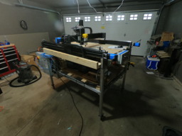
1510 Workbee Modified

Discussion in 'CNC Mills/Routers' started by Jacob Lotter, Dec 2, 2018.

  1. Jacob Lotter

    Jacob Lotter Well-Known
    Builder

    Joined:
    Oct 26, 2018
    Messages:
    34
    Likes Received:
    59
    Yup that should work out well. I plan on making these plate kits and selling them as well.
     
  2. bsuisham

    bsuisham New
    Builder

    Joined:
    Jan 11, 2019
    Messages:
    3
    Likes Received:
    0
    Been searching around for just this, bought my 1510 back in January and have been completely frustrated with the non-stop wheel adjustments and just when you think you have it perfect it goes out again after a short time cutting, pretty much every time from what I can tell it starts binding and causing the Y axis to go out of whack. I am doing some larger pieces of acrylic with some detailed etching, when I do a small piece I have no major issues but once I try to run on a 48" piece and the Y axis has a lot of travel it is very problematic, a 1 or 2 mm mis-alignment will destroy the entire job and there goes a $200 piece of acrylic. I slowed the machine right down to try to reduce this, which helps a bit but still need to find a better solution and takes forever running at slow speeds and need it to run faster to get a cleaner etch, get a lot of back-fill when running slow, which means hrs with a Dremel after cleaning it up, which I was hoping to not have to do.

    After spending as much as I have already I am approaching this cautiously, so I plan to start with changing out the Y axis wheels with the linear bearings as you have shown but keep the belt drive for now. I see you changed yours out to screw driven as well, was the belt drive still problematic after you installed the linear rails? Did you use slide in nuts in the C beam to secure the rails or did you drill and tap the linear rails to the C beam?

    I was also curious about the X axis mod, did you use the same rail and just cut it down or did you order a different rail?

    I really need to get some consistency to this machine and spend more time cutting and less time adjusting, seems so far I spend more time setting the machine up then cutting with it.

    Interested in the mod kits as well, did you start producing them? It would be great to have a little more clearance, hoping once I get converted to the linear rails to make that mod as well.

    Looking forward to making this conversion, hope it helps resolve many of the issues I have been having so I can spend more time reliably cutting.
     
  3. Jacob Lotter

    Jacob Lotter Well-Known
    Builder

    Joined:
    Oct 26, 2018
    Messages:
    34
    Likes Received:
    59
    The biggest reason I ditched the belts is that you can easily get that 1-2mm of lash right out of belt stretch from either too much load or from simply changing direction under load. You can measure this by pulling your gantry just a bit and measuring how easy the belts stretch. I also went to the lead screwes because the linear bearings do create more friction than the wheels and i figured in that configuration the motors would constantly stall out, I never tested it as I really wanted lead screws regardless. I used drop in T nuts on Amazon, i Believe they are in the "Parts List" Tab to see what i used, I do need to update it, I never drilled into the rail once. The total of parts to do this cost around $500 dollars excluding my plates (Just mechanical upgrade) I also made an electrical upgrade to this entire system seen on my other build "CNC ESS Controls System" . And with the plates, I'm almost finished with everything, which I plan on posting about soon as I did the modification to my machine first to test it out, come to around $600 as of now because It takes about 16 hours to create the 8 plates and bearing blocks + material cost. Just so you see a number of how much this can cost. Feel free to PM me for more details Bsuishan I'd be more than happy to talk to you about other details regarding this.
     
  4. azrael_sk

    azrael_sk New
    Builder

    Joined:
    May 13, 2015
    Messages:
    10
    Likes Received:
    4
    So, it seems to have worked well. Just one quick cut in aluminum for now, but seems much more rigid than before. Although there is still some play on the x axis when pushing the router by force. Guess the whole x axis c beam is still twisting a bit.
    Will test more by milling some new corner plates to rise the workbee after I get back home in 2 weeks.
    IMG_20190418_160444.jpg IMG_20190418_123953.jpg IMG_20190417_151933.jpg
     
  5. sharmstr

    sharmstr OpenBuilds Team
    Staff Member Moderator Builder Resident Builder

    Joined:
    Mar 23, 2018
    Messages:
    2,059
    Likes Received:
    1,448
    I could be wrong, but I bet it has more to do with the wheels on the Y than it does with any play in X. You can test this by trying to rotate the Y plates to check for play.
     
  6. azrael_sk

    azrael_sk New
    Builder

    Joined:
    May 13, 2015
    Messages:
    10
    Likes Received:
    4
    Thanks for the suggestion, I will try it. I have installed the linear rails on X and Z only for now. I'll upgrade the Y later.
     
    sharmstr likes this.
  7. sharmstr

    sharmstr OpenBuilds Team
    Staff Member Moderator Builder Resident Builder

    Joined:
    Mar 23, 2018
    Messages:
    2,059
    Likes Received:
    1,448
    I would do some testing for you, but I've done the opposite of you. I've only installed them on Y. Haven't got around to installing on X or Z yet :)
     
  8. azrael_sk

    azrael_sk New
    Builder

    Joined:
    May 13, 2015
    Messages:
    10
    Likes Received:
    4
    No problem,I started with those as they seemed much more challenging than the Y :). As for the play, it only happens a bit when pushing on the router in the Y axis direction (z axis fully extended). I tested it in the middle of the gantry. In the X direction it is rock solid.
     
    sharmstr likes this.
  9. Metalguru

    Metalguru Veteran
    Builder

    Joined:
    Dec 29, 2015
    Messages:
    752
    Likes Received:
    548
    This is why I don't advocate using OB C-beam in designs over 1000mm axis length. The C-beam is just not stiff enough, particularly if you want to machine aluminum. That and the belt drive makes the 1500mm machines very poor performers. I refuse to sell them at all.

    You need an X axis that is WAY stiffer than a c-beam can provide. With the linear bearings, you could add a second c-beam behind the main one since you no longer have the rear gantry plate. You would have to figure out a good way to connect them together to increase the stiffness.

    MG
     
  10. azrael_sk

    azrael_sk New
    Builder

    Joined:
    May 13, 2015
    Messages:
    10
    Likes Received:
    4
    Well the backplate is actually still there as the backslash nut is attached to it. I was thinking of relocating the acme screw to the top and attach the backlash nut to the top linear guide L bracket. Then it would be possible to remove the backplate and either add another c beam or an aluminum or even steel plate on the back of the existing c beam. I can't remember exactly, but someone modified an ox this way. It should be on the openbuilds forums.
    I have the 1000 x 1000 leadscrew version, and generally can't complain except for the problem stated in previous posts.
    I did some aluminum cutting before the upgrade, it is not perfect, but so far acceptable for my purposes. Of course I would not complain if it was better :)
     
  11. Lee Hilton

    Builder

    Joined:
    Oct 17, 2018
    Messages:
    2
    Likes Received:
    0
    I am going to make some similar mods to my Workbee 1515 that I am cutting down to a 1510. I have a question about your Y-axis lead screw bearings and retainer. It looks like your bearing is on the outside of the Y-axis end plate(s). I am curious if you are only using the outside bearing, or are you perhaps using a second bearing on the inside of the Y-axis end plate?

    [​IMG]

    On the motor side I am curious if you are doing something similar with the bearings. I can't tell from any of your photos, but it almost looks like you are leaning on the coupler to support the entire threaded rod.

    [​IMG]

    Great build. This has given me direction on how to clean up a lot of the bad behaviors I get out of my machine.
     
  12. Jacob Lotter

    Jacob Lotter Well-Known
    Builder

    Joined:
    Oct 26, 2018
    Messages:
    34
    Likes Received:
    59
    There are bearings on both sides that are seated in a bore within the plates. The bearings would not fit inside the C channel so they are outside of it. There are retainers on the opposite side of the motors and the motor coupler is being used as a retainer on the motor side.
     
  13. Jacob Lotter

    Jacob Lotter Well-Known
    Builder

    Joined:
    Oct 26, 2018
    Messages:
    34
    Likes Received:
    59
    And that peice you are pointing to in the first pic is a 3d printed drag chain mount that came with my kit from ooznest. I really need to update these pics as alot of things have changed.
     
  14. Lee Hilton

    Builder

    Joined:
    Oct 17, 2018
    Messages:
    2
    Likes Received:
    0
    Thank you for the information. Anything you would change about the bearing mounts?

    I saw your images of the plates you cutout, that looks super solid.
     
  15. Jacob Lotter

    Jacob Lotter Well-Known
    Builder

    Joined:
    Oct 26, 2018
    Messages:
    34
    Likes Received:
    59
    The only thing I would change is to incorporate flange style bearings with set screws. But that proves to be a problem with nema23 motor mounting holes.

    Overall I'm very happy with my settup, and even happier that I can take time to cut things out instead of just modifying the machine! Haha

    If you have any other questions, feel free to contact me.
     
  16. Hafizi5299

    Builder

    Joined:
    Sep 25, 2018
    Messages:
    4
    Likes Received:
    1
    Hai there openbuilds members.. i just need a suggestion on linear rail type for y axis workbee CNC, is it ok if using HG guide rail type? I found a good price for HGR15 type but i just wanna ask the professional before i buy the rail.
    Thanks in advance
     
  17. Skip S.

    Skip S. Well-Known
    Builder

    Joined:
    Jun 6, 2018
    Messages:
    63
    Likes Received:
    23
    Quick question on this build - do you have measurements on the locations you drilled holes to mount the blocks for the gantry plates? Or was this a little bit of "point and pray" with location drilling?
    Thanks!
     
  18. sharmstr

    sharmstr OpenBuilds Team
    Staff Member Moderator Builder Resident Builder

    Joined:
    Mar 23, 2018
    Messages:
    2,059
    Likes Received:
    1,448
    Go the the build tab, then into the files tab. Dimension drawings are in there.
     
    Skip S. likes this.
  19. Skip S.

    Skip S. Well-Known
    Builder

    Joined:
    Jun 6, 2018
    Messages:
    63
    Likes Received:
    23
    I saw the drawings for the bearing blocks and the hole locations, I must have missed the one for the plates. I'll check again after work.
    My hgh rails are showing up today, but have to order more blocks and the hardware. Mods to come soon!
     
  20. Jacob Lotter

    Jacob Lotter Well-Known
    Builder

    Joined:
    Oct 26, 2018
    Messages:
    34
    Likes Received:
    59
    From what I remember I never put the hole locations in the files as I had done a dry fit up to pin the block in the correct locations. But since then I have changed my whole plate/block system. I will get around to updating the drawings soon.
     
    sharmstr and Skip S. like this.
  21. Skip S.

    Skip S. Well-Known
    Builder

    Joined:
    Jun 6, 2018
    Messages:
    63
    Likes Received:
    23
    Got my final linear block done this morning (sneaking parts in between runs at work lol) so I was wondering if anyone had tips to set the linear rails on the machine, placing blocks, drilling etc.
    Thanks for any info!
     
  22. Skip S.

    Skip S. Well-Known
    Builder

    Joined:
    Jun 6, 2018
    Messages:
    63
    Likes Received:
    23
    Nothing?
    Ok, guess I'll just try to figure it out.
     
  23. sharmstr

    sharmstr OpenBuilds Team
    Staff Member Moderator Builder Resident Builder

    Joined:
    Mar 23, 2018
    Messages:
    2,059
    Likes Received:
    1,448
  24. Skip S.

    Skip S. Well-Known
    Builder

    Joined:
    Jun 6, 2018
    Messages:
    63
    Likes Received:
    23
    Thanks Sharmstr, appreciate the info!
    Would you happen to have the dimensions you used to drill the bolt holes for the Y plates to attach? Or would you happen to know if there are there resources for CAD files on the XY plates for the locations of the holes?
    I'm guess I'm too used to working with prints..so I get hazy when freewheeling.
    Sorry for all the questions

    Made a quick paint sketch - the info I'm looking to glean is side mount hole locations like the ones circled.. I can't find info in the CAD section about any of the main axis plates, that's why I ask. Maybe I'm looking in the wrong place?

    Dropbox - example.jpg - Simplify your life
     
    #54 Skip S., Mar 3, 2020
    Last edited: Mar 3, 2020
  25. Jacob Lotter

    Jacob Lotter Well-Known
    Builder

    Joined:
    Oct 26, 2018
    Messages:
    34
    Likes Received:
    59
    Glad things are going well with your machine.

    Sorry all for not being able to update on lingering questions on here as I has started a New job as a Controls Engineer a few months back. Now get to design, program, and install massive industrial control system!!

    next up to build a large CNC with Allen Bradley Kinetix Servos! one day at least
     
  26. Jacob Lotter

    Jacob Lotter Well-Known
    Builder

    Joined:
    Oct 26, 2018
    Messages:
    34
    Likes Received:
    59
    Set one side out as far as mechanically possible perpendicular to the linear rail, then put the gantry on with the other side still loose. as you move the gantry through the system, tighten the linear rails down.

    As far as the Main axis plates I never put the CAD files up on those yet as I wanted to see how well they worked first, which was a long time ago I know. Will get around to updating that in time.
     
  27. Skip S.

    Skip S. Well-Known
    Builder

    Joined:
    Jun 6, 2018
    Messages:
    63
    Likes Received:
    23
    Oh no worries, I understand that life happens.
    If anyone could point me to prints for the axial plates so I could tell where to punch holes to mount the linear blocks I'll happily head that direction.
    That's the only thing that's holding me back from being able to continue upgrading.
    Something I could open in solidworks to dimension would be perfect if available on here somewhere.
     
    #57 Skip S., Mar 3, 2020
    Last edited: Mar 3, 2020
  28. sharmstr

    sharmstr OpenBuilds Team
    Staff Member Moderator Builder Resident Builder

    Joined:
    Mar 23, 2018
    Messages:
    2,059
    Likes Received:
    1,448

    Those holes use the existing holes in the Y plate. You can get those dimensions in the files and drawings section of the workbee build: OpenBuilds Workbee 1510 (60" x 40")
     
  29. Skip S.

    Skip S. Well-Known
    Builder

    Joined:
    Jun 6, 2018
    Messages:
    63
    Likes Received:
    23
    Perfect! Thanks sharmstr, I'll check these out at lunchtime!
     
  30. twr412

    twr412 New
    Builder

    Joined:
    Jan 15, 2020
    Messages:
    3
    Likes Received:
    0
    Where did you guys source the lead screws and linear bearings from? The link from the parts list has the linear bearings sold out. I am fed up with these belts and wheels. I have a bunch of aluminum that I can use to reinforce the machine and make it more rigid once I get some decent bearings that don't break the bank.
     

Share This Page

  1. This site uses cookies to help personalise content, tailor your experience and to keep you logged in if you register.
    By continuing to use this site, you are consenting to our use of cookies.
    Dismiss Notice