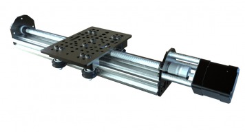
Mark, I need to build a 4-axis foam cutter. I was planning to build something like what you've done here. I want to use ACME 1/2 screws and NEMA23 motors. You have everything needed, but only in NEMA17 size. Any change you can make NEMA23 sized parts? Great site. Great ideas. Will
Hi Will thank you and welcome to OpenBuilds I have not posted it as a build yet, but I started a simple two tower hotwire cutter that uses NEMA 17 since there is no real forces for hot wire foam cutting I would think there would be no need for the 23's unless its a very BIG hotwire But to answer your question, Yes OpenBuilds part store is working into having more NEMA 23 related parts for larger stronger builds.
Mark, Yeah, no doubt NEMA17 is capable of the average foam cutter. I am looking for a 24" x 16" cutting area. I think most people forget that speed is your enemy when it comes to cutting foam...at least to an extent. I will design the parts and pass it on. Will
Very cool Will! Looking forward to your build. I found these bad boys for inspiration that we could use to build car bodies or airplanes http://www.hotwiredirect.com/products/cnc-foam-cutting-machines/8300-cnc-specifications/
Hi @Veej Did you download the example model file? That's the best way to get an idea on how you want to start your build. There are many ways to go about making a build like this and the example models should give you a good start. Hope this helps
Yes I have and I do like both the approaches; one where the lead screw is from the motor to the other end and one where the lead screw does not go the full length of the V slot rail. The questions is if one is more robust than the other? If it is the first one, will the threaded motor mount plate holding the end of the lead screw come in the way for attaching a perpendicular V slot rail? If I follow the second design, this should not be the problem though. Just want to be sure before I order parts since this is my first time!
Hi @Veej NP bro this is what its all about There should be no difference as the robust will come from how well the cart is mounted to the rail not the lead screw. The main advantage of having the bearing plate (threaded rod plate) on the opposite end is for longer runs of the threaded rod so that when turning at high speeds it helps to keep the end from whipping around. on short runs or slower truing machines (hotwire cutter) this will not be an issue. Real world experimentation on what works best for your design is really the best way to see if it will do what you want.
Thank you so much for the clarification. Even though my application does not require fast movement, I think it will be best to go with the full length lead solution. I'll mount the V slot rail that is going to be perpendicular to the mechanism on the back side at the bearing plate end. I believe Universal L brackets should work for a robust mount. If you have other suggestions, please let me know. Thanks for all your help.
Hi, Sorry to butt in on this (dormant) thread - but I thought it a waste to start an identical one. I am an aircraft designer/builder (full size and RC), and I'm sick and tired of buggering up airfoils on my gravity-fed hotwire system. I know other guys seem to produce perfect airfoils with these sorts of systems, but not me. So I thought I'd look into CNC hotwiring them. At first I hit all the big ticket items and ALMOST gave up till I stumbled on the Phlatprinter which fascinated me. And then I found your site. And then saw all your great builds. My favorite so far is the OX. But I only need a hotwire system, which means two Z-towers and 2 X-rails. So I got to thinking I could build a simplified OX with two towers and no Y-gantry. I guess I could - but now I see you're working on a genuine 4-axis hotwire which is GREAT. My only (?) issue is that I need to cut wing cores with chords of 1100mm (X-axis). So I would need something with at least that amount of travel. Z-axis requirements are minimal (a 1100mm airfoil is only 165mm high...) Any advice? Having re-read this post, I think I should have posted it elsewhere, but I'm happy that I got it down, at least... I'm based in Brisbane, so it would mean ordering all the parts from Perth, but even though that is ALMOST another country, it is a lot easier than ordering from the US... Regards, and looking forward to hearing from you. Duncan
I built an x axis similar to the image above but I am having an issue and could use some advice. I can't seem to get the alignment of the lead screw and post on motor correct. when I tighten the motor mount bracket, the carriage won't move smoothly but if I loosen it, then I get a wobbly motion in the bracket. Any suggestions? Also, the Nema 17 motor doesn't seem to have any real torque. Is that to be expected with that size? Thanks in advance.
Build list seems incorrect. You need the 40mm aluminum spacers in order to use the 45mm screws. Not the 1.5 inch spacers
Nope, it's correct. The screw has to pass through a 3mm plate first. With the 1.5 inch spacer this leaves 3.9mm of thread to connect into the motor. The 40mm spacers would only leave 2mm which is a bit short.
Can someone from OpenBuilds let me know when the full NEMA 17 kit (bundle) will be back in stock? I can see that just two of the bundle components are not in stock, but the in-stock date for these has changed from today to unknown. Thank you...
Hello John. We are working hard to restock the parts needed to complete the Bundle. The current ETA is within a week. If you would like to place a pre-order, please contact the OpenBuilds Part Store at http://support.openbuilds.com/support/home and they'll be happy to help. Thank you for your support
Hello everyone, I made some drawings based on the SketchUp file and the STEP documents and published some models in GrabCAD (related to this project) I hope it will be of benefit to everyone First model Second model Third model Fourth model
Hello, Does anyone know what range of static and dynamic loads this build could take is? Also, would it be possible to install a hand-crank in lieu of a motor? Thanks
Hello, Great job on the CAD! I noticed the CAD is the 500mm version. Is there any difference between the 500mm and the 250mm version, aside from the length of the extrusion and lead screw? -Thanks
Well we would always be partial to the BlackBox but the BlackBox is set up really for a cnc machine and you may only need to drive 1 or 2 of these. If thats the case you could use some of the single axis drivers