Welcome to Our Community

Some features disabled for guests. Register Today.

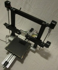
Frauthy 3D Printer

Discussion in '3D printers' started by MechEng, Aug 8, 2014.

  1. MechEng

    MechEng New
    Builder

    Joined:
    Mar 2, 2014
    Messages:
    15
    Likes Received:
    4
    MechEng published a new build:

    Read more about this build...
     
  2. Mark Carew

    Mark Carew OpenBuilds Team
    Staff Member Moderator Builder Resident Builder

    Joined:
    Jun 28, 2013
    Messages:
    2,758
    Likes Received:
    2,440
    @MechEng Great looking machine, thank you for sharing!
     
  3. Seul Kee

    Seul Kee New
    Builder

    Joined:
    Mar 10, 2014
    Messages:
    16
    Likes Received:
    1
    I also thank you for your detailed explanation.
     
  4. Funk

    Funk New
    Builder

    Joined:
    Sep 25, 2014
    Messages:
    4
    Likes Received:
    0
    Awesome. That sure looks like it was designed in SolidWorks. Any chance of getting the part and assembly files?
     
  5. MechEng

    MechEng New
    Builder

    Joined:
    Mar 2, 2014
    Messages:
    15
    Likes Received:
    4
    Hey!

    Sorry for the delayed response. School can be pretty time consuming!

    I do have the SolidWorks files, and I plan on submitting them here once I can package them in a professional manner.

    Happy holidays!
     
  6. Keith Davis

    Keith Davis Veteran
    Builder

    Joined:
    Dec 11, 2013
    Messages:
    507
    Likes Received:
    398
    A suggestion on your change to 60x20 X axis extrusion - move the single wheel on the outside to the center slot instead of the same top slot as the inside top wheel. The resulting triangle will let you adjust the wheel-to-rail tension only on that wheel (assuming the other two on the other side are true)

    Great progress. This looks like an easy to build design. Make a great kit.
     
  7. MechEng

    MechEng New
    Builder

    Joined:
    Mar 2, 2014
    Messages:
    15
    Likes Received:
    4

    Good thinking! Will try that out asap.
     
  8. bobs987

    bobs987 New
    Builder

    Joined:
    Dec 19, 2014
    Messages:
    2
    Likes Received:
    0
    This looks like a great built, Solid. I'm currently sourcing parts for this now, can’t wait to bust the saw out! I too would love to see the assembly files, I'd like to scale it up to accept a 10"x10" bed if not 12"x12". It looks like this can be done by extending the z and x axis members. Is there anything I'm overlooking?
    MechEng, Great idea extending the x axis for more a more ridged build and the suggestion Keith Had is spot one. Will definitely be doing this to my build. Happy Holidays, enjoy your winter break.
     
  9. MechEng

    MechEng New
    Builder

    Joined:
    Mar 2, 2014
    Messages:
    15
    Likes Received:
    4
    Yep you would pretty much just extend the axis proportionally for a larger bed.

    The current lengths I have for the frame for a 200mm x 200mm x 200mm build volume are:

    - (1) 20mm x 80mm x 590mm for the y axis (front to back)
    - (1) 20mm x 60mm x 365mm for lower width of frame
    - (1) 20mm x 60mm x ~510mm for x axis (left to right)
    - (1) 20mm x 40mm x 365mm for upper width of frame
    - (2) 20mm x 40mm x 385mm for height of frame

    A person could probably just barely get a 250mm x 250mm x 200mm (10" x 10" x 8") build volume with those dimensions, but it would be a really tight fit.

    Couple things to note:

    - I'm using a Budaschnozzle hot end, and have it set to drop ~10mm below the x-axis plate and 30mm (from the plate surface to tip of nozzle) out of the x-axis plate. You might consider the depth of the extruder you plan on using before cutting the y-axis extrusion. You should still be fine if you're doing a direct drive extruder, but some of them can get pretty beefy and it's probably just best to check before you make that cut.
    - The solid shaft couplings I have are just slightly too wide at 24.75mm diameter to fit into the pocket behind the x-axis. If I had slightly thinner solid shaft couplings, I would be able to get an additional 30mm of z travel.
    - Currently, my 8mm lead screws are ~370mm in length. I did this so I could experiment with different captive nuts if need be. You can still use 300mm lead screws for 200mm of z travel if you use brass captive nuts or put a taller captive nut oriented length-wise up the lead screw. This is what I'm currently using, but I haven't been able to test their longevity/ reliability:

    http://www.ebay.com/itm/Brass-Flange-Nut-For-DIY-Build-3D-Printer-Z-Axis-8mm-Stainless-Steel-Lead-Screw/141428125155?_trksid=p2045573.c100033.m2042&_trkparms=aid=111001&algo=REC.SEED&ao=1&asc=20131017132637&meid=f835724c6a97455d8e0da864e344d63d&pid=100033&prg=20131017132637&rk=3&rkt=4&sd=381018039835

    - I didn't end up putting the additional bits of 20x80 under the printer. I thought it would help make the printer more rigid, but they just took up space and required more brackets.
    - I'm doing Bowden extrusion. I ended up making a spool holder out of 20x20 that sits behind the printer because I couldn't come up with a place to mount the extruder on the frame where the Bowden tube didn't put a weird bend in the filament. PLA isn't very friendly with sharp turns.

    I think that's about all I really changed. Let me know if you run into any issues.

    Currently working on making a clean looking Ramps/ Arduino enclosure, a micro-fine z-stop mount, a geared (metal) bowden extruder, and a LCD mount. Will post those files here once I confirm they're good to go.
     
  10. MacSpengo

    MacSpengo New
    Builder

    Joined:
    Dec 28, 2014
    Messages:
    4
    Likes Received:
    0
    great build. I have a questions though. How did you mount the wheels on the back side of the X axis? I do not see any plates in you BOM and was just wondering how you did it. Could you post a picture of this as well? Great looking setup, I am building one right now.
     
  11. MacSpengo

    MacSpengo New
    Builder

    Joined:
    Dec 28, 2014
    Messages:
    4
    Likes Received:
    0
    Never mind. If I would have read your update, my questions would have been answered with pictures.

    Great work, looks fantastic. Hope to have mine up and running tomorrow.
     
  12. bobs987

    bobs987 New
    Builder

    Joined:
    Dec 19, 2014
    Messages:
    2
    Likes Received:
    0

    Wow thank you for the detailed reply. I cant wait to get this going, Starting to order the parts this week. I have to build a new desk first, Current one is a bit on the small side. How is the Bowden setup working for you? I've read both good and bad things about this setup.
     
  13. bearwood

    bearwood New
    Builder

    Joined:
    Nov 8, 2014
    Messages:
    4
    Likes Received:
    2
    These updates look like they will do the trick. The solid shaft couplings are a must.
    I had a huge amount of fun and learnt so much building my rendition of the original design. I added a open builds Cube connector to add the 3rd wheel to each side of the X axis gantry.
    I changed the drive over to CoreXZ which is working really well now that I changed over to a Bulldog driven bowden system.
    I look into the Y axis drive that you've suggested, as although it works ok, it adds more length which I'm not sure is needed.
     
  14. MacSpengo

    MacSpengo New
    Builder

    Joined:
    Dec 28, 2014
    Messages:
    4
    Likes Received:
    0
    Would you be willing to share a stl file of your captive nut adapters? It looks like a much easier approach than drilling the metal plate.
     
  15. MechEng

    MechEng New
    Builder

    Joined:
    Mar 2, 2014
    Messages:
    15
    Likes Received:
    4

    I was using a budaschnozzle because that's what I use on my other printer, but I wanted to see how light I could get the x assembly, and I also wanted to maybe dabble in printing polycarbonate.

    For now, I've set aside the budaschnozzle and I'm trying a dual bowden setup utilizing Prometheus hotends.

    http://www.dta-labs.com/products/prometheus-hot-end-v1-1

    Here's a shot of my current extruder setup:

    http://i.imgur.com/bLmKs4r.jpg

    I haven't ran any test prints with the new extruder, but I did with the budaschnozzle. It printed pretty good, but I was using some really horrible filament where the diameter was 3 +/- 0.2mm. When I get this dual extruder setup all bolted up, I'll be sure to post some pictures of the first test prints. Kind of a side note, but if you're going with bowden, I would definitely recommend Ultimachine filament. It's pretty expensive, but the diameter and quality is so consistent, nothing else really touches it.
     
  16. MechEng

    MechEng New
    Builder

    Joined:
    Mar 2, 2014
    Messages:
    15
    Likes Received:
    4

    Sounds pretty slick!
     
  17. MechEng

    MechEng New
    Builder

    Joined:
    Mar 2, 2014
    Messages:
    15
    Likes Received:
    4
    I was hoping to release all finalized files at the same time, but I suppose it wouldn't hurt to release one file.

    Just keep in mind, things could change, or I might change the design for some reason, so use at your own discretion.

    I've posted the adapter plate in the, "files" tab.
     
  18. Huey Brantley

    Builder

    Joined:
    Jan 22, 2015
    Messages:
    2
    Likes Received:
    0
    What stage are you currently in? Close to releasing everything?
     
  19. MacSpengo

    MacSpengo New
    Builder

    Joined:
    Dec 28, 2014
    Messages:
    4
    Likes Received:
    0
    This is fantastic. I was able to get these printed out and they worked like a charm! Thanks so much for posting these, I have been taking pics of the build and will be posting them soon.
     

Share This Page

  1. This site uses cookies to help personalise content, tailor your experience and to keep you logged in if you register.
    By continuing to use this site, you are consenting to our use of cookies.
    Dismiss Notice