Welcome to Our Community

Some features disabled for guests. Register Today.

890KV OX RC spindle

Discussion in 'Other Builds' started by Robert Hummel, Jan 13, 2014.

  1. Rick 2.0

    Rick 2.0 OpenBuilds Team
    Staff Member Moderator Builder Resident Builder

    Joined:
    Dec 20, 2013
    Messages:
    2,892
    Likes Received:
    1,551
    @Marios,

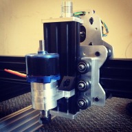
    My apologies, I should have credited the photo. It is from Inventables and is likely a real photograph.
     
  2. mightyevo

    mightyevo New
    Builder

    Joined:
    Mar 13, 2014
    Messages:
    27
    Likes Received:
    1
    hi
    i am having a few silly problems
    sketchup wont(afaik) give me a model or simple shape to export to cambam/solidworks-hsm.
    what toolchain are people here using?
    how do i take this and turn it into parts? i know its me and not the files. or if someone can give me dimensions of holes ect i can redraw in solidworks.
    sorry for all the questions, been making mostly "pretty" things in wood, these will be my first "parts" where everything has to fit together perfectly.
    thnx
    mevo
     
  3. Gareth

    Gareth New
    Builder

    Joined:
    Jan 23, 2014
    Messages:
    15
    Likes Received:
    8
    I've been doing research on Spindles and I'm quite takes with this idea. this seems to be one of the few ways we might get to a 1 killowatt spindle on 120V house current. If you have a 240V circuit then there are any number of VFD units that you can use in the 12KW range. On 120V its either small DC spindles (<500W) or bulky, noisy, heavy routers.

    My only issue is I don't see how you can make one without a lathe or perhaps a really well sorted out CNC machine.
     
  4. David the swarfer

    David the swarfer OpenBuilds Team
    Staff Member Moderator Builder Resident Builder

    Joined:
    Aug 6, 2013
    Messages:
    3,462
    Likes Received:
    1,915
    I use Sketchup + Sketchucam plugin. I am the current maintainer of SketchUcam but a lot of people have been involved in making it work as well as it does.

    SketchUcam is 2.5D, though it does have a 3D mode it is not yet very good at all.
    for an example of cutting a complex part, read this
    http://www.phlatforum.com/xenforo/threads/generating-gcode-for-3d-object.3322/#post-36741

    That aside, Sketchup can export DXF format , and there are plugins for exporting just about everything else, like STL.
     
    mightyevo likes this.
  5. Rick 2.0

    Rick 2.0 OpenBuilds Team
    Staff Member Moderator Builder Resident Builder

    Joined:
    Dec 20, 2013
    Messages:
    2,892
    Likes Received:
    1,551
    If you're willing to settle for settle for square on your first run through, all you really need is a drill press. At its essence, this is really just a series of very precise holes drilled in stacked aluminum plates. Round could probably be achieved using router templates but that would take a fair amount of patience with the thickness of material being used. You could always start with round stock but you would have to take care to get the ends perfectly square.

    Ultimately, the easiest way would probably be getting to know Robert Hummel. ;)
     
  6. Rob Taylor

    Rob Taylor Master
    Builder

    Joined:
    Dec 15, 2013
    Messages:
    1,470
    Likes Received:
    749
    To be fair, there are VFDs that'll convert 120VAC 1~ to 220VAC 3~ for spindles(check out LightObject), but the problem there is that you're limited by the current capacity of a single ring main. Assuming a standard 15A circuit, you can get 1.8kW out of the wall. If VFDs are reasonably efficient (and I hear that's one of their main selling points, depending on how much you believe the manufacturers' claims), you might be able to get 1.2-1.5kW into your spindle. That's at full power too, which isn't necessarily all the time. 1kW shouldn't be hard.

    Obviously, a 220V 40A line will provide over four times that, and if you can afford it, VFDs higher than the typical 1.5-3kW are readily available. There doesn't appear to be any real need if you're using aluminium extrusion to build, though- all you're going to end up doing is flexing your structure. Once you're up to and beyond 1kW, I'm not sure 8020/V-Slot is realistically the way to go, depending of course on the size of your machine, unsupported spans, all that good stuff. Some simple beam deflection calculations would help there, assuming typical load and instantaneous cutting forces by workpiece material, cutting bit, spindle power and maybe feed rate are tabulated somewhere.

    This seems to be rather OT for RC BDC motor conversions though. :p
     
  7. KerryH

    KerryH New
    Builder

    Joined:
    May 26, 2014
    Messages:
    63
    Likes Received:
    21
  8. KerryH

    KerryH New
    Builder

    Joined:
    May 26, 2014
    Messages:
    63
    Likes Received:
    21
    Been a minute since anyone has shared anything in here.

    Any thoughts on using a slower motor such as this 380kv but running it with a 24v psu?
     
  9. Tweakie

    Tweakie OpenBuilds Team
    Moderator

    Joined:
    Jan 18, 2014
    Messages:
    784
    Likes Received:
    326
    Looks good but you may need an 80 Amp PSU with adequate cooling.

    Tweakie.
     
  10. Nick W

    Nick W Well-Known
    Builder

    Joined:
    Oct 22, 2014
    Messages:
    99
    Likes Received:
    61
    I've been investigating using a smoothie controller board for a future build. Since it has a few pwm outputs available it "should" be able to control the ESC. Is this the circuit I need to build to control the brushless motor? I read this thread start to finish again and it seems like there were some jumps from here to the end.
     
  11. Tweakie

    Tweakie OpenBuilds Team
    Moderator

    Joined:
    Jan 18, 2014
    Messages:
    784
    Likes Received:
    326
    Jestah likes this.
  12. Nick W

    Nick W Well-Known
    Builder

    Joined:
    Oct 22, 2014
    Messages:
    99
    Likes Received:
    61
    Ah yeah. That's the part that puts a wrench into the works. I knew there was something I missed.
     
  13. Jeremy Young

    Builder

    Joined:
    Nov 13, 2014
    Messages:
    22
    Likes Received:
    4
    Hey Guys,

    I decided to give this a go, fortunately I have access to a full size CNC mill so modified the design slightly. I haven't had a chance to test the spindle out yet but have a 60A brushless ESC and servo tester which should do the trick.

    Pics Below:

    image.jpeg image (2).jpeg image (1).jpeg

    I did have one question though, I had planned to mount the ESC to my Z axis V-slot and have power cables running all the way to my power supply. I was reading up on some RC aircraft stuff and they recommend adding a pair of capacitors across the power cables for each 10cm of added power cable! Did any of you bother with that? I did notice my ESC already has a pair of caps but the info I read advised adding more.

    Cheers
    J
     
    Shinohara, oni305 and Nick W like this.
  14. Robert Hummel

    Robert Hummel Custom Builder
    Moderator

    Joined:
    Nov 14, 2013
    Messages:
    978
    Likes Received:
    715
    Love it and wish I had the means to make a beautiful housing like that :)
    I would go with 608zz bearings as they are rated for the RPMs you will be pushing.
    I just picked up some flanged 608z for a rebuild :)
    Great work I'm sure it will work awesome
    As for the esc I mounted it in my controller to keep the pwm wires short.
    I then used sheilded power supply cable like they use in hospital grade plugs for the 3 winding wires.
    It was 12 feet long and I had no issues :)
    Keep in mind this is not a RC condition so your not running off a depleting battery ;)
     
  15. Jeremy Young

    Builder

    Joined:
    Nov 13, 2014
    Messages:
    22
    Likes Received:
    4
  16. Robert Hummel

    Robert Hummel Custom Builder
    Moderator

    Joined:
    Nov 14, 2013
    Messages:
    978
    Likes Received:
    715
  17. Jeremy Young

    Builder

    Joined:
    Nov 13, 2014
    Messages:
    22
    Likes Received:
    4
    Hi Everyone,

    @Shinohara expressed an interest in using my model to machine a spindle for himself, so I have exported the models as .STP files and attached them. Obviously you will need access to a CNC mill but feel free to use these models to machine your own.

    A couple of things to consider:
    - These housings are designed to fit 608 2RS bearings (same as 608ZZ, but with rubber instead of metal shields) so the holes are modeled as 22 mm diameter. I altered my CAM sequence to take an extra 0.01 mm of material off to get a perfect push fit on the bearings (22.02 mm overall diameter). I often model on the safe side and perform this "on machine" adjustment as I am machining to get the perfect fit on critical parts.
    - Be sure to assemble the housing and motor using the shaft to align all the components.
    - When mounting to the Z-axis v-slot, the clearance to insert and tighten the mounting screws (10 mm allen cap screws) is quite tight and you'll need to use a ball ended allen key to tighten them, alternatively you could use hex head bolts.

    Cheers,
    J
     
  18. Jeremy Young

    Builder

    Joined:
    Nov 13, 2014
    Messages:
    22
    Likes Received:
    4
  19. Jeremy Young

    Builder

    Joined:
    Nov 13, 2014
    Messages:
    22
    Likes Received:
    4
    Hi Guys,

    I have finally gotten my machine all together, here's a video of it doing it's first cuts.

    www.youtube.com/embed/ExGllS2Ewg0

    This is through 20mm plywood using a 4 mm solid carbide End Mill, 1 mm step-downs, feeding at 1000 mm/min. What are everyone else's experiences with this type of cutting? It's quite slow cutting large pieces but sounds like it's working quite hard, do you think I can take deeper cuts and/or move faster?

    I am slightly worried because I tried cutting aluminum which didn't go so well. It seemed like the machine was struggling, taking 0.1mm cuts at 500 mm/min and in one instance the cutter caught an edge and got thrown around a bit. I feel like the gantry head and z axis just isn't stiff enough to handle metal cutting.

    The other issue could be that the spindle isn't up to the task? Do you think i'd fear better with a router than spins 20k+ RPM??

    Would appreciate some guidance on this!

    Cheers
    J
     
  20. Tweakie

    Tweakie OpenBuilds Team
    Moderator

    Joined:
    Jan 18, 2014
    Messages:
    784
    Likes Received:
    326
    Hi Jeremy,

    I am pleased to see you have your machine up and running - nice job with the build. :thumbsup:

    Whilst some have cut metals with a gantry design of machine it is never going to be totally as successful as a milling machine design. Rigidity is the problem here so anything you can do to stiffen everything up will be beneficial but wood, plastics and many composites are where this design of machine really excels.

    Tweakie.
     
  21. Jeremy Young

    Builder

    Joined:
    Nov 13, 2014
    Messages:
    22
    Likes Received:
    4
    Hi @Tweakie, thanks for you reply.

    Yeah obviously there are limitations with this style of machine.

    I would really like to be able to cut at a slightly faster rate, even through wood, do you think I would benefit from moving up to a 6mm cutter? Hopefully this spindle is powerful enough to handle it.

    Also, do the polycarbonate extreme V-wheels make a big difference?

    I do have my eye on some linear rails and ball screws to build a super mill! Still gantry style though.

    Cheers,
    J
     
  22. Tweakie

    Tweakie OpenBuilds Team
    Moderator

    Joined:
    Jan 18, 2014
    Messages:
    784
    Likes Received:
    326
    I think you will do better with a 6mm cutter but spindle power is something you may have to try and see.
    Unfortunately I have no experience with the polycarbonate wheels, perhaps someone else can advise on this.

    Tweakie.
     
  23. Jeremy Young

    Builder

    Joined:
    Nov 13, 2014
    Messages:
    22
    Likes Received:
    4
    I got hold of a 6 mm wood routing end mill and managed to do some good cuts for a friend that is prototyping a stool design.

    Ended up running at 500 mm/min and taking passes of 3.8mm, still took 5 passes to get through 19mm plywood though! Cut quality was good, even if a bit slow. Does this sound about the same as what you guys would run your machines at with this spindle?

    I feel like I might be able to take deeper cuts, it really was getting very noisy though, so much so that we were wearing ear protection. It was hard to tell, but it sounded like there may have been some cutter chatter happening due to the cutter running through such a deep channel/cut.

    Cheers
    J
     
  24. Jestah

    Jestah Well-Known
    Builder

    Joined:
    Dec 4, 2013
    Messages:
    148
    Likes Received:
    84
    the poly carb wheels are a really good addon for the Z axis.

    Not quite finished with the build so no real world cutting result differences but I can feel the Z is FAR stiffer at the longer travel compared to the standard solid V wheels
     
  25. SecretSpy711

    SecretSpy711 Well-Known
    Builder

    Joined:
    Jan 29, 2015
    Messages:
    31
    Likes Received:
    27
    Forgive me if you've already mentioned it, but have you measured the runout of the RC spindle? Currently I am using a DeWalt DW660 and my runout is horrible, .007" to .010" typically, measured at the cutter shank. This is mostly due to the fact that I can't buy a precision collet for that router.
     
  26. Kyo

    Kyo Veteran
    Staff Member Builder Resident Builder

    Joined:
    Feb 27, 2014
    Messages:
    673
    Likes Received:
    702
    Started on my spindle mount, Decided to try 3d printing it. How long will it last ? not a clue lol but it does seem rather solid.

    Lower Spindle mount. Printed in ABS.... Photos are without any cleanup..
    [​IMG]

    [​IMG]

    [​IMG]

    [​IMG]

    (blue is just a bit of painters tape stuck on.)
     
  27. Kyo

    Kyo Veteran
    Staff Member Builder Resident Builder

    Joined:
    Feb 27, 2014
    Messages:
    673
    Likes Received:
    702
    I think it is about time to get a camera and stop using this old phone. Parts look so much better in person. They printed great. Nice Design Mr. Young! Everything is going together smoothly. Need to place a order for bolts and bearings before finial assembly.

    [​IMG]

    [​IMG]

    If any one else would like to trying printing a set. Attached are the STL files I made from young's stp files above..
     

    Attached Files:

    #177 Kyo, Feb 1, 2015
    Last edited: Feb 1, 2015
  28. Steve B

    Steve B Well-Known
    Builder

    Joined:
    Dec 12, 2014
    Messages:
    47
    Likes Received:
    47
    I was going to ask about this. Given the load, I can't see this pulling a lot of amps, even when cutting. Have you measured the amps while cutting? I have several ESC's laying around 40-50A.

    I just won a motor for $15 w/ shipping from HK. Assuming they follow through with fulfilling the auction.
     
  29. chuangatronic

    Builder

    Joined:
    Aug 7, 2015
    Messages:
    8
    Likes Received:
    1
    Looking for some help on this build.

    I've built this setup using a mystery cloud 80A esc and a servo tester, but it seems like my RPM isn't as high as it should be. Would bearing drag cause this problem?

    Also, could someone give me their max feeds and pass depth they've been able to achieve in aluminum? I've only been able to manage 1/64 pass with a 150mm/min feed
     
  30. chuangatronic

    Builder

    Joined:
    Aug 7, 2015
    Messages:
    8
    Likes Received:
    1
    It's the 890kV motor described in this project running on a 12V 40A meanwell power supply adjusted up to 13.9V. According to the math, I should be running up to 12k RPM. It doesn't seem to be capable of running at that rate and I get an oscillating noise from the spindle, it sounds like my bearings are dragging and are maybe slightly out of alignment. I've done a tear down and reassembly with no real difference in performance.

    Just did another teardown and there's finally evidence that my bearings were toasted. I'm going to remove them and get rid of the spacer stack and run it like the version 1 of this project.
     
    #180 chuangatronic, Apr 1, 2016
    Last edited: Apr 1, 2016

Share This Page

  1. This site uses cookies to help personalise content, tailor your experience and to keep you logged in if you register.
    By continuing to use this site, you are consenting to our use of cookies.
    Dismiss Notice