Welcome to Our Community

Some features disabled for guests. Register Today.

openBuilds FreeBURN-2-Mini V-slot CO2 Laser (40-50w)

Discussion in 'Laser Cutters' started by openhardwarecoza, Jan 20, 2015.

  1. openhardwarecoza

    openhardwarecoza Journeyman
    Staff Member Builder

    Joined:
    Aug 9, 2014
    Messages:
    134
    Likes Received:
    138
    Nick W likes this.
  2. Mark Carew

    Mark Carew OpenBuilds Team
    Staff Member Moderator Builder Resident Builder

    Joined:
    Jun 28, 2013
    Messages:
    2,758
    Likes Received:
    2,440
    Did not expect this, but what an awesome surprise! This is a great idea Peter and we can't wait to see how the Mini FreeBURN CO2 Laser turns out!
    OpenBuilds will do what it can through the FairShare Give Back Program to help with this great open source build.
    Thank you for sharing
    Mark
     
  3. openhardwarecoza

    openhardwarecoza Journeyman
    Staff Member Builder

    Joined:
    Aug 9, 2014
    Messages:
    134
    Likes Received:
    138
    :) Thanks Mark - I'll try and raise some from the community at large first :) I may press on your button for the OpenBuilds parts itself

    Oh and this one WILL have a Z axis - see the 120mm clearance between the nozzle and the floor (;
     
    Mark Carew likes this.
  4. Mark Carew

    Mark Carew OpenBuilds Team
    Staff Member Moderator Builder Resident Builder

    Joined:
    Jun 28, 2013
    Messages:
    2,758
    Likes Received:
    2,440
    That sounds great Peter! This is what the FairShare Program is all about :thumbsup:
    Thank you for taking the time to do this build, its going to be a great addition to our shop here. Can't wait to get one built!
    Mark
     
    Pawlenko M likes this.
  5. openhardwarecoza

    openhardwarecoza Journeyman
    Staff Member Builder

    Joined:
    Aug 9, 2014
    Messages:
    134
    Likes Received:
    138
    Added the front panels, and Z motor cutouts. Started working on the BOM with costing too. Sitting at $714 before cutting the chassis - rough estimate should be under $100 since the Freeburn1 panels was MUCH bigger and cost me $120

    laverv4mini.PNG
     
  6. openhardwarecoza

    openhardwarecoza Journeyman
    Staff Member Builder

    Joined:
    Aug 9, 2014
    Messages:
    134
    Likes Received:
    138
    So couple of updates over the last few days.

    1. Alex Lee sponsored $50 towards the project - a BIG thank you Alex!

    2. Changes to drive system: Initially I had 20x40s on X and Y, and also had the X belt running behind the 20x40 - which all in all needed almost 120mm of X space to accomodate. I changed over to
    2.1 Using Mini V Wheels
    2.2 20x20 V Slot
    2.3 Placing the X belt on top of the axis rail instead of behind it.
    2.4 Aligning the position of the X motor and other parts so they are in the 80mm 'wings' so you loose nothing of the real movable envelope - maximise cutting area
    With the mini v-wheel based carriages that 120mm of dead space dropped to 65mm :)
    explo-drive-mech.PNG

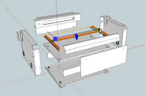
    3. I've started to add the bends, plan the bolt holes, and add HSF8 supports into the base for some 'printrbot style' z rods. I thought about using V Slot for the Z rails but its going to be a LOT bulkier than a 8mm rod and a LM8UU - so unfortunately the LM8UUs wons. Today I must draw the Z carriage. Here's some views of the changes and a exploded view of the new design. Its designed to be made out of 2mm lasercut mild steel and 2mm lasercut aluminum. I will add notes to the model but mostly the side pieces and the middle floor, and top front base and laser tube tray are made of steel - to ensure a very rigid frame. The other components will be aluminum so save some weight.


    explo5.PNG explo3.PNG explo2.PNG explo1.PNG min5.PNG min4.PNG min3.PNG min2.PNG min1.PNG
     
    Kyo and Joe Santarsiero like this.
  7. openhardwarecoza

    openhardwarecoza Journeyman
    Staff Member Builder

    Joined:
    Aug 9, 2014
    Messages:
    134
    Likes Received:
    138
    Ok so the Z axis was quick work. But only because I cheated a little. Using a belt linked setup with pulleys etc would have made it a lot more complicated. Best off all when I did the costing, 4 x NEMA17s from Massdrop costs LESS than a large enough closed loop belt does! So 4 motors it is :)

    Basically in each corner we have a NEMA17 hanging under the floor on 40mm standoffs - this allows the couplers to also be inside the base and provide maximum Z move distance
    Each motor holds a M8 rod and theres a small 3d Printed part in each corner to trap an M8 nut

    A sheetmetal frame sits on trapped LM8UUs in the same little plastic part, and will have mesh stretched over it (blue part in render below)

    Tray suspended on all 4 corners
    z axis.PNG


    Some detail of the nut/bearing trap block
    zaxis.PNG

    View from below the floor showing the motor suspended on 40mm standoffs and the coupler nicely out of the way in this area
    zmotorsfrombottom.PNG
     
  8. openhardwarecoza

    openhardwarecoza Journeyman
    Staff Member Builder

    Joined:
    Aug 9, 2014
    Messages:
    134
    Likes Received:
    138
    Another view of the Z axis, from the front with the front panels and sides hidden:

    z axis viewed from front.PNG
     
  9. Rick 2.0

    Rick 2.0 OpenBuilds Team
    Staff Member Moderator Builder Resident Builder

    Joined:
    Dec 20, 2013
    Messages:
    2,892
    Likes Received:
    1,551
    Are you controlling all 4 motors off one driver?
     
  10. openhardwarecoza

    openhardwarecoza Journeyman
    Staff Member Builder

    Joined:
    Aug 9, 2014
    Messages:
    134
    Likes Received:
    138
    Indeed but i've done before without issue and keep in mind these are not running of dinky little A3988 or DRV8824s. Those DQ542MAs are highly intelligent drivers with enough oomph and control to pull it off
     
  11. openhardwarecoza

    openhardwarecoza Journeyman
    Staff Member Builder

    Joined:
    Aug 9, 2014
    Messages:
    134
    Likes Received:
    138
    @Rick 2.0 - based on your scepticism - and since this is a in-progress design - I'll add in holes to mount screws into F608Z flange bearings / OR / the 4 x motors with a NEMA23 sliding motor mount inside the base too - so if you feel so inclined you can also route a belt and pulleys to turn the 4 screws? Always good to have a set of alternate options built in right? :)
     
  12. Rick 2.0

    Rick 2.0 OpenBuilds Team
    Staff Member Moderator Builder Resident Builder

    Joined:
    Dec 20, 2013
    Messages:
    2,892
    Likes Received:
    1,551
    Please don't perceive it as skepticism. It was more of a case of just askin'.

    And yes, options are always good.
     
  13. openhardwarecoza

    openhardwarecoza Journeyman
    Staff Member Builder

    Joined:
    Aug 9, 2014
    Messages:
    134
    Likes Received:
    138
    :) I prefer to perceive it as sskepticism- because thats a really good thing :)

    Nothing worse than working in / on a project and no-one questions your ideas. Engineering thrives on the input of doubt - either to prove that what you designed will work - or like in this case to say - hold up lets add an option just in case it doesnt work for everyone.

    There's an old saying that goes "If you're the smartest person in the room, you're in the wrong room" - well thats my motto. So please feel free to 'just ask', downright criticise, or give advice and input at any point in this project - someone is bound to learn from it :)
     
    Joe Santarsiero and Rick 2.0 like this.
  14. openhardwarecoza

    openhardwarecoza Journeyman
    Staff Member Builder

    Joined:
    Aug 9, 2014
    Messages:
    134
    Likes Received:
    138
    Z: Done

    Right so I basically struck two birds with one stone on the new Z axis. I cloned the middle floor to be the bottom floor :)
    Now theres two sets of NEMA17 patterns perfectly above each other on the middle and top floor. So if you go for individual Z motors, you simply bolt in NEMA17s to the middle floor with 40mm spacers....

    newz.PNG

    OR: If you want to rig up some pulleys to do a single-belt system. Use OpenBeam's awesome NEMA17 to 608 adapters to mount some 608 bearings in the middle and floor pieces , and slide your leadscrew into them. Put some 8mm bore pulley onto the screws and start routing the belt. If you need idlers you can slide some F608Z bearings onto the smooth rods too.
    (No render yet - sorry)

    http://www.thingiverse.com/thing:78766

    Printable_608_to_NEMA17_Bearing_Adaper_preview_featured.jpg
     
  15. openhardwarecoza

    openhardwarecoza Journeyman
    Staff Member Builder

    Joined:
    Aug 9, 2014
    Messages:
    134
    Likes Received:
    138
    Y Axis: Added mounting holes on the right hand side to mount a NEMA23, with a small closed loop GT2 belt, that drives the rear driveshaft.

    y driveshaft.PNG
     
  16. openhardwarecoza

    openhardwarecoza Journeyman
    Staff Member Builder

    Joined:
    Aug 9, 2014
    Messages:
    134
    Likes Received:
    138
    The bulk of the mechanical design is now finished. So time to start working on the "small" things that usually end up being the BIG time wasters - to plan for wire routing, and small screws, and clearances and and and... you get the picture.

    First part done relatively quickly though: X Minimum and X maximum Endstops.

    Now for many of you the parts may look foreign - but in an industrial design these are the defacto endstop standard. Its called a SN-04 Inductive sensor. They run from 6-30v and is similar NPN type as the 3D printing crowd uses as a Z height sensor. In fact I use them for Z probes too on my 3d printer (see a photo I posted a few months ago https://plus.google.com/104034368033227202956/posts/iQEX28rgKET )
    While great for probes though, I am more interested in the SN-04s for their intended purpose. Endstops.
    This is not my first run with them, for about 6 months or so I have had a few of my machines running on these instead of mechanical switches. Example: https://plus.google.com/104034368033227202956/posts/JSmtJxyiyWX - X endstop on a VSlot based printed.

    The SN04 sensors make for really reliable, highly repeatable and - most importantly inside a sooty laser cabinet - a SEALED sensor that will work reliable for years

    3528_0_Web.jpg

    Incorporated into our laser model, here's where they'll go.
    You may also see another 3rd one below the one on the left (below the X Min endstop) - that will be the Y Max endstop - not in its final position yet

    Xmin-maxendstops.PNG

    Oh, and if you were wondering - they are around $3 each, we need 6 for endstops on the machine, plus two more as door closed sensors (safety first)

    http://www.aliexpress.com/item/24-V...-PNP-normally-open-three-line/2036692956.html
     
  17. openhardwarecoza

    openhardwarecoza Journeyman
    Staff Member Builder

    Joined:
    Aug 9, 2014
    Messages:
    134
    Likes Received:
    138
    Y Max Endstop - sits in a cutout halfway inside the laser tube compartment - its basically in front of the no1 mirror mount's foot but far enough - no issues with clearance :)

    ymax.PNG
     
  18. openhardwarecoza

    openhardwarecoza Journeyman
    Staff Member Builder

    Joined:
    Aug 9, 2014
    Messages:
    134
    Likes Received:
    138
    And it seems this time of day I like doublebacking over my previous design within a few minutes.
    While finding a spot for the X MIN endstop, I figured a more elegant solution to the XMIN and XMAX endstop - so disregard that previous post please :)

    I placed them onto the side panel instead. Using slots instead of screw holes allows tweaking the max and min positions of the axis too:
    newxends.PNG

    So in this orientation, how will we trigger the sensors? Easy - add one simple bend to the X carriage:
    Lets call this a 'flag'
    x end flag.PNG

    And when the carriage moves in under the sensor, the flag is in the correct position and ready to trigger the endstop:
    flag under sensor.PNG


    PS: Don't you just love building things in Sketchup as Components and how it allows you to drag/move them around on the axis's they will move in later to see where they clear/catch/trigger/etc? Love it...
     
    Mark Carew likes this.
  19. AnRkey

    AnRkey New
    Builder

    Joined:
    Jan 25, 2015
    Messages:
    1
    Likes Received:
    0
    I'm so excited!!!!
     
  20. Mordecaix89

    Builder

    Joined:
    Dec 9, 2014
    Messages:
    3
    Likes Received:
    0
    Been following the build and want to say great job.

    For the lens and mirror from Wuhan Laserlands on alixpress, when they want the diameter of the mirrors, the focal length and left or right direction what did you go with?
     
  21. Tweakie

    Tweakie OpenBuilds Team
    Moderator

    Joined:
    Jan 18, 2014
    Messages:
    784
    Likes Received:
    326
    Very neat idea with the end-stops, in fact the whole design is neat.
    Keep up the good work my friend, this is going to be a machine to be proud of. :thumbsup:

    Tweakie.
     
  22. openhardwarecoza

    openhardwarecoza Journeyman
    Staff Member Builder

    Joined:
    Aug 9, 2014
    Messages:
    134
    Likes Received:
    138
    We want 25mm mirrors for no1 and no2.
    For the laser head - its a 20mm mirror for no3, with a 18mm diameter lens. For focal length a 50.8mm is a good all rounder. The 25.xmm focals work better for engraving, while a 70.xmm cuts 'better' in that it has a straighter edge (but slower due to the larger spot diameter - so pretty much a no-go on a small laser)

     
  23. openhardwarecoza

    openhardwarecoza Journeyman
    Staff Member Builder

    Joined:
    Aug 9, 2014
    Messages:
    134
    Likes Received:
    138
    Thanks Tweakie! I appreciate your feedback!

     
  24. openhardwarecoza

    openhardwarecoza Journeyman
    Staff Member Builder

    Joined:
    Aug 9, 2014
    Messages:
    134
    Likes Received:
    138
    Thank goodness I hosted my file here on OpenBuilds. SouthAfrica is currently in the grip of a phenomenon called "load shedding" which is basically a 3rd world government run electricity providers way to handle its own inability to manage the grid by simply "switching off" or "shedding" sections of the grid a few times per day to manage the load... ): - I think I need to figure out how emigration works...

    Anyway in one of these hard power cuts I just lost a drive in my dev box. And yes its the drive where I store my eagles cad, sketchup, dxfs etc... Bad luck. Luckilly the version up here was not far behind so I'll be able to rework it back into what I had lost. And the rest of my stuff are mostly up to date on the last backup I made to an external in Nov last year + github. So not too much lost...

    I also ordered some more parts:

    https://plus.google.com/104034368033227202956/posts/bPuENgyAxHV
     
  25. openhardwarecoza

    openhardwarecoza Journeyman
    Staff Member Builder

    Joined:
    Aug 9, 2014
    Messages:
    134
    Likes Received:
    138
    Took me about a day but I think I added back all the changes lost yesterday :)

    Next I need to run to the hardware store and get some Hinges - having them in hand makes sure the CAD is correct...
     
  26. Mordecaix89

    Builder

    Joined:
    Dec 9, 2014
    Messages:
    3
    Likes Received:
    0
    I could not imagine living in conditions like that, thanks for the information on the mirrors.
     
  27. Rick 2.0

    Rick 2.0 OpenBuilds Team
    Staff Member Moderator Builder Resident Builder

    Joined:
    Dec 20, 2013
    Messages:
    2,892
    Likes Received:
    1,551
    Invest in a UPS/battery backup system, you'll be glad you did. Even the little one I have gives me 5 minutes to shut down and controls any potential spikes that may come through the lines.
     
  28. openhardwarecoza

    openhardwarecoza Journeyman
    Staff Member Builder

    Joined:
    Aug 9, 2014
    Messages:
    134
    Likes Received:
    138
  29. openhardwarecoza

    openhardwarecoza Journeyman
    Staff Member Builder

    Joined:
    Aug 9, 2014
    Messages:
    134
    Likes Received:
    138
    Added the lid and lower front panel
     
  30. openhardwarecoza

    openhardwarecoza Journeyman
    Staff Member Builder

    Joined:
    Aug 9, 2014
    Messages:
    134
    Likes Received:
    138
    Started the flattening process to get workable DXFs to send off to the factory this week :)

    1. Sort out the components to be made
    flatpack.PNG

    2. Convert them to flat version

    flattened.PNG
     

Share This Page

  1. This site uses cookies to help personalise content, tailor your experience and to keep you logged in if you register.
    By continuing to use this site, you are consenting to our use of cookies.
    Dismiss Notice