Welcome to Our Community

Some features disabled for guests. Register Today.

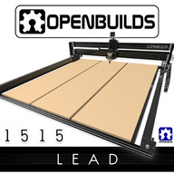
OpenBuilds LEAD CNC Machine 1515 (60" x 60")

Discussion in 'CNC Mills/Routers' started by OpenBuilds, Sep 29, 2020.

  1. Peter Van Der Walt

    Peter Van Der Walt OpenBuilds Team
    Staff Member Moderator Builder Resident Builder

    Joined:
    Mar 1, 2017
    Messages:
    14,917
    Likes Received:
    4,290
  2. Brian Hagen

    Builder

    Joined:
    Mar 14, 2021
    Messages:
    21
    Likes Received:
    8
    Every motor works fine along with it’s associated wiring as long as I don’t plug them into the y2 slot of the black box. If I take the vibrating motor and plug it into the z axis slot, it works fine.
     
  3. Peter Van Der Walt

    Peter Van Der Walt OpenBuilds Team
    Staff Member Moderator Builder Resident Builder

    Joined:
    Mar 1, 2017
    Messages:
    14,917
    Likes Received:
    4,290
    Ok, contact the store via Support for further assistance
     
  4. romamaker

    romamaker Well-Known
    Builder

    Joined:
    Nov 14, 2017
    Messages:
    69
    Likes Received:
    56
    I've got a question about the 1515. Description mentions working with 4' x 4' sheets, but the specs list the working area as 46" x 49".
    My question is, can you load up a full 48" wide sheet in the machine, but it just can't reach the outer 2 inches? Or is there only room to handle a 46" wide piece?
     
  5. Giarc

    Giarc OpenBuilds Team
    Staff Member Moderator Builder Resident Builder

    Joined:
    Jan 24, 2015
    Messages:
    3,008
    Likes Received:
    1,676
    You can load up a full sheet. The space between should be approximately (a little over) 1350mm (53") if my math is right.
     
    #155 Giarc, Feb 21, 2022
    Last edited: Feb 21, 2022
  6. Eddie T. Head

    Builder

    Joined:
    Mar 8, 2022
    Messages:
    1
    Likes Received:
    0
    I would like to build a large torsion box 75" x 65" out of wood. Is there a good way to join two torsion boxes that are dead flat? I have searched the inter-google until my fingers are numb and have not been able to find any answers--any help or direction would be greatly appreciated!
     
  7. Metalguru

    Metalguru Veteran
    Builder

    Joined:
    Dec 29, 2015
    Messages:
    752
    Likes Received:
    547
    Eddie

    Probably your best bet is to make two 65x37.5" torsion boxes, with MDF top and bottom. Then join the two boxes together to make your final size, gluing the joint. Have 2 more sheets of MDF 75x32.5" ready and glue them on across the joint between the two boxes (while the glue in the joint is still wet). If you want to make absolutely sure, do the same on the bottom of the torsion boxes.

    You could use thinner 3/8" or even 1/4" MDF to skin the boxes, and then use 3/4" for the second skin. White PVA glue will give you a little more working time than yellow Aliphatic glue. Or, as I assume it won't be getting wet, Titebond liquid hide glue has even better open time.

    MG
     
    Giarc likes this.
  8. Evilspawn

    Evilspawn New
    Builder

    Joined:
    May 4, 2022
    Messages:
    34
    Likes Received:
    7
    What's the best way to route the power cable to the spindle? It's not long enough to run through the drag chain/flexible tubing as far as I can tell.
     
  9. Peter Van Der Walt

    Peter Van Der Walt OpenBuilds Team
    Staff Member Moderator Builder Resident Builder

    Joined:
    Mar 1, 2017
    Messages:
    14,917
    Likes Received:
    4,290
    Put it in a swing arm Swing Arm
    Don't put it in the cable chain, it can cause EMI: docs:blackbox:faq-emi [OpenBuilds Documentation]
     
  10. rtlee

    rtlee New
    Builder

    Joined:
    Aug 4, 2022
    Messages:
    2
    Likes Received:
    0
    Hi all — I'd like to extend the y-axis of the 1515 to double (or even triple) the length. I think it would be fairly straightforward to extend the C-beam itself but could use some advice on what to replace the lead screws with to cover this span effectively. Should I opt for something like rack and pinion over that kind of length?

    Any advice or pointers to relevant builds would be appreciated, thanks.
     
  11. Metalguru

    Metalguru Veteran
    Builder

    Joined:
    Dec 29, 2015
    Messages:
    752
    Likes Received:
    547
    Not sure why you would want to do this, what do you make surfboards or something? Just curious: why on earth would you need a 20ft bed?

    This is not really an answer to your inquiry, I just thought I would bring it up for fans of the larger machines. A company called makerstore.cc out of Oz is now selling "c-beam heavy", a much strengthened version of c-beam with 2.7x thickness on all the webs and 72% higher strength over regular c-beam. This should be a worthwhile upgrade for the x axis on any machine. They have a US warehouse, and the material is available in lengths up to 2.4m.

    C-Beam HEAVY - Maker Store USA

    They also stock plastic rack and pinion that fits inside the v-slot rails, it comes in 500mm lengths which can be butted together to form any length rack. Pinion gears are available in several different sizes as well.

    Gears and Racks Archives - Maker Store USA


    MG
     
  12. Evilspawn

    Evilspawn New
    Builder

    Joined:
    May 4, 2022
    Messages:
    34
    Likes Received:
    7
    That's an interesting product.
    Their site feels...off to me. It's very strange that their logo is identical to Openbuilds' just blue instead of black. Is that even legal?
     
  13. Metalguru

    Metalguru Veteran
    Builder

    Joined:
    Dec 29, 2015
    Messages:
    752
    Likes Received:
    547
    I've purchased a LOT of stuff from them and have had no issues whatsoever. They are very responsive and answer questions promptly. Just be aware that the US distribution hub is just a warehouse, there is no support staff here. All email inquiries go to Oz, so be patient since there is a large time difference and it usually takes 24-48 hours for them to get back to you. The only issue I have is that their shipping rates are pretty high, OB has brokered a deal with Fedex to get killer rates, whereas Makerstore just ships at Fedex's regular prices. If you have any kind of account with a shipper like DHL or Fedex, you should probably arrange for your own shipping to save some money.

    As far as the logo is concerned, I don't know, but I believe the OB logo itself is open sourced just like the products. In any case, the Makerparts logo is just enough different to not infringe, IMHO. I think anyone selling the open sourced parts are able to use the logo. Don't quote me, I'm no lawyer.

    See this thread: Is OpenBuilds itself Open Source?

    MG
     
  14. rtlee

    rtlee New
    Builder

    Joined:
    Aug 4, 2022
    Messages:
    2
    Likes Received:
    0
    Thanks for the pointer. I want to build a large cnc for flattening large wood slabs as well as smaller things like joinery, signs, engravings, etc.
     
  15. Tyler Skelton

    Builder

    Joined:
    Feb 16, 2023
    Messages:
    9
    Likes Received:
    2
    Im currently attempting to build the LEAD 1515 and have run into a lot of questions, concerns and troubleshooting following the assembly videos both mechanical and electronics. The video itself is well made, Matt does a great job at breaking down each step of the build process but there are certain times in the videos were his wording has left me confused and caused me to double back several times to insure I followed along correctly and id like to see if anyone could clear those up.
    -Step 3 @(6:06)
    The parts listed on this step include (4) Aluminum spacers 3mm but when Matt is going over the parts and pointing out each part individually, they are not included visually, nor does he use 3mm spacers while completing the step. This reoccurs in Step 6 @(20:15), Step 9 @(30:55), Step10 @(34:27) After so many steps asking for these spacers but not incorporating them into the step left me confused and began to lose confidence in my build and I had to double-back several times. (To my recollection, I only used 3mm aluminum spacers for the nut blocks and have (12) spacers left after completing the mechanical build video. This seems incorrect, although I have not encountered any alignment or spacing issues?
    - Step 4 @(15:15) Matt explains a method to get the v-slot rail flush with the gantry plate by pressing the v-slot down onto your level working space to achieve alignment. But if the eccentric wheels are in the fully open position they protrude past the gantry plate which brings the v-slot below the gantry when pressing it down to the work surface. Not being able to achieve similar results made me think I had the wheel assembly built incorrectly when really it was just the fully open position of the wheels which he adjusts back to the fully open position a few seconds later making me realize that his eccentric nuts changed while he was tightening down the wheel assembly. That being said, to simplify this step you just need to align the bottom of the v-slot with the bottom of the gantry plate and don't overthink it like I did. This reoccurs @(27:00) and @(52:25) in the video. Please let me know if this is inaccurate
    - Step 6&9&10 @(20:15), @(30:55), @(34:27) previously mentioned 3mm Aluminum spacer not being used
    - Step 14 @(1:05:45) The single L bracket placement is concerning since it will be raised higher than the opposite end of the beam when you install the T-nut to secure the drag chain. Im assuming this rise is too little to effect the precision since its approx 2mm?

    At the end of the mechanical build I had random parts not used, this is concerning since most parts did not have extra, while others had an additional+10units of such as 3mm aluminum spacers and 5m 20mm screws?

    Electronic video

    -Step 6 after assembling all the wiring and fitting them into the flex tube, he says, "im going to come here to the left side of the machine" (when really he is working off the back, right side of the machine). hearing that made me think that I had just wiring everything backwards, when really he was positioned behind the machine and states that he is working from off of his left. I realized this was just my incompetence flexing itself but wanted to leave it here in case someone else encounters the same situation. This happens a few more times like when he mentions he will be mounting the blackbox on the right side, he just means his current right since he is behind the machine but location wise, the black box was mounted on the back left side of the build.
    - Step 7 Black box mounting location. im installing a Blackbox 32x and noticed the SD insert would be inaccessible if mounted it according to the video? Also the location itself seems it would be subject too debris? I work with epoxy and corian a lot and could see it settling into the blackbox since its so ventilated?
    - Step 8 wire management. Id personally wait on this step, zip tie the connectors together before checking if you have proper connection and power could result in having to snip those zip ties. I struggled getting a single zip tie around the connector and found that they are not long enough to do so, although Matt accomplished it in the video, im skeptical on if he actually caught a tooth when tightening down. If so he is a zip tie wizard! Not being able to do so myself lead to frustration since this seems like the simplest of tasks. Easy solution that took me way too long to think of, tie two zips together extending the length and making it struggle-free.
    -Installation and connection
    In the video he connects to COM 6, while I only had COM 5 option. I assume this is fine, would just like to know more in detail what this means.

    - Tensioning lead screws
    My Y1 motor will not engage and therefore cannot tension, checked wiring and colors match up and connectors are fully engaged on motor connections and blackbox. So with only 9 minutes left of instructional video, I am stuck here with an eerie feeling that im still hours or even days away from completion. my incompetence knows no bounds, so feel free to get a good laugh at it, I sure do. Ive attached some photos that may help explain my troubleshooting.

    Any tips or advice would be greatly appreciated!
     

    Attached Files:

  16. Tyler Skelton

    Builder

    Joined:
    Feb 16, 2023
    Messages:
    9
    Likes Received:
    2
    Not exactly sure what the black plate was for? my guess was it is a mounting plate for the power supply box?
     
  17. Giarc

    Giarc OpenBuilds Team
    Staff Member Moderator Builder Resident Builder

    Joined:
    Jan 24, 2015
    Messages:
    3,008
    Likes Received:
    1,676
    He does not mention them, but yes they are listed onscreen. I believe he mentions the nut blocks were already attached prior to the steps which come after 6:06. That is what they were for.

    In the parts list, there should have been a total of 14. Maybe you got a bunch of extras. If not, then you must have forgot to use them on all the nut blocks.

    upload_2023-2-17_17-18-4.png
     
  18. Tyler Skelton

    Builder

    Joined:
    Feb 16, 2023
    Messages:
    9
    Likes Received:
    2
    Giarc, Thanks for your prompt response! Checked all my nut blocks, and confirmed i used a total of 14. So, im gonna chalk it up to i was given double the amount needed. Thanks again
     
    Giarc likes this.
  19. Tyler Skelton

    Builder

    Joined:
    Feb 16, 2023
    Messages:
    9
    Likes Received:
    2
    Currently trying to work through fault indicators on my Blackbox32x (3 out of 4 triggered). So I went back to the video where Matt explains proper wire alignment @(1:06:23) where he says " from left to right, we are going to insert Red,Blue,Green, and Yellow. I imitated his wiring, ensured all wires are locked in and additionally inspected to see if i had shoved the wires in too much and clamped the plastic tubing but all was well. Tried again and faults are still present. So i pulled up the NEMA23.png document and it displays the exact opposite in wire configuration (yellow, green, blue, red)?! Which is correct?
     
  20. Alex Chambers

    Alex Chambers Master
    Moderator Builder

    Joined:
    Nov 1, 2018
    Messages:
    2,772
    Likes Received:
    1,358
    Depends whose motors they are - Openbuilds instructions are correct for recent steppers from Openbuilds, but there is no standard colour coding for motors from other suppliers.

    docs:blackbox-4x:faq-identify-motor-coils [OpenBuilds Documentation]

    Alex.
     
  21. Peter Van Der Walt

    Peter Van Der Walt OpenBuilds Team
    Staff Member Moderator Builder Resident Builder

    Joined:
    Mar 1, 2017
    Messages:
    14,917
    Likes Received:
    4,290
    Contact the store via Support > New Ticket for assistance. Please include a link to this thread
     
  22. crash5050

    crash5050 New
    Builder

    Joined:
    Oct 10, 2014
    Messages:
    21
    Likes Received:
    2
    With the way the LEAD1515 machine is set up, using 4 separate "quads" for the spoil board, has anyone figured a way out to do a vacuum hold down system on it?
     
  23. crash5050

    crash5050 New
    Builder

    Joined:
    Oct 10, 2014
    Messages:
    21
    Likes Received:
    2
    Oh, and is anyone else running multiple Z gantries on their machines?

    Crash5050
     
  24. Evilspawn

    Evilspawn New
    Builder

    Joined:
    May 4, 2022
    Messages:
    34
    Likes Received:
    7
    Does anyone know the weight of the 1515 (fully loaded version) with MDF spoil board, and the modular table to match?
     
  25. Andrew A

    Andrew A New
    Builder

    Joined:
    Jul 11, 2021
    Messages:
    6
    Likes Received:
    2
    Yup. Me.
     

    Attached Files:

    #175 Andrew A, Aug 24, 2023
    Last edited by a moderator: Aug 24, 2023
    mike dauteuil likes this.
  26. Fifth_rendition

    Builder

    Joined:
    Mar 2, 2023
    Messages:
    22
    Likes Received:
    4
    I have a fully loaded 1515 with mdf spoiler boards, mdf on the below shelf and the modular table. I don't know of any way I could weigh it for you. It's HEAVY with the MDF is on. I could probably push it without the wheels on, if the spoil board wasn't on.
     
  27. Pierre St-Denis

    Builder

    Joined:
    Aug 29, 2023
    Messages:
    1
    Likes Received:
    0
    Hello Mark,

    interested in purchasing the 1515 but with the higher Z axis. I don't see it as an option in the kit, so do I have to order the individual items using the parts list and replace the side columns, C-Beam and Lead screw or is there another way to just click the bundle and request the Higher Z axis.

    Thanks
     
  28. Peter Van Der Walt

    Peter Van Der Walt OpenBuilds Team
    Staff Member Moderator Builder Resident Builder

    Joined:
    Mar 1, 2017
    Messages:
    14,917
    Likes Received:
    4,290
    You can contact the store directly via Support > New Ticket to interact with the Store itself for order/sales/shipping questions.
     
  29. alphabeta77

    Builder

    Joined:
    Jan 10, 2016
    Messages:
    21
    Likes Received:
    3
    Hi there,

    Interested in the Lead1515, however I read a lot of people pointing towards linear rails as being superior to ballscrews and wheels.

    Certainly on my existing openbuilds CNC (much older) I note lots of dust builds up on the wheels which ultimately may affect accuracy.

    Are there any opinions/thoughts on how much improvement that linear rails would make?
     
  30. JustinTime

    JustinTime Veteran
    Builder

    Joined:
    Dec 18, 2013
    Messages:
    780
    Likes Received:
    257
    I use linear rails AND ballscrews. Nothing wrong with the ballscrews. It's the wheel that some people object too.
     

Share This Page

  1. This site uses cookies to help personalise content, tailor your experience and to keep you logged in if you register.
    By continuing to use this site, you are consenting to our use of cookies.
    Dismiss Notice