Welcome to Our Community

Some features disabled for guests. Register Today.

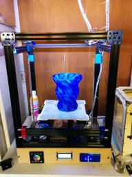
Triple C-Bot

Discussion in '3D printers' started by adamcooks, Feb 11, 2015.

  1. adamcooks

    adamcooks Well-Known
    Builder

    Joined:
    Nov 6, 2014
    Messages:
    244
    Likes Received:
    65
    adamcooks published a new build:

    Read more about this build...
     
    Dark-Noir likes this.
  2. Carl Feniak

    Carl Feniak Journeyman
    Builder

    Joined:
    Mar 18, 2014
    Messages:
    654
    Likes Received:
    246
    Can you post a pic of how the lead screw belt pullys are attached and how the lead screws are supported? Do the lead srews neck down in size or are they continuous diameter?
     
  3. adamcooks

    adamcooks Well-Known
    Builder

    Joined:
    Nov 6, 2014
    Messages:
    244
    Likes Received:
    65
    IMG_20150211_203138.jpg
    The Zen Toolworks lead screws are turned down to 5mm from the TR8*8 20mm on both ends. Its pretty simple mounting, the leadscrew sits in a flange bearing, gravity and 36T pulley with set screw locks whole thing in place. The shafts are round on the screws and flatted on the stepper so I can sync the screws easier.
    IMG_20150119_140513.jpg
    That was my first attempt at making a 16mm hole for my bearings, silly me i told the CAD to make a 16mm hole, and not 16.19. I started with your motor mounts, to keep the spacing consistent with the acme nut holder.
     

    Attached Files:

  4. Bclough

    Bclough New
    Builder

    Joined:
    May 27, 2014
    Messages:
    2
    Likes Received:
    0
    Imagine having all three lead screws on independent drivers. That would be an interesting yet complicated bed leveling technique.
     
  5. adamcooks

    adamcooks Well-Known
    Builder

    Joined:
    Nov 6, 2014
    Messages:
    244
    Likes Received:
    65
    You could use it to autolevel fairly easily. put the nozzle in a predetermined location, and drive the bed up to it.... would be sync nightmares all day while printing.

    The spacing of the crossmembers of my Z stage is based on the Replicator. When Scott releases his brilliant mechanical auto leveling I planned on using it. [​IMG]Read about it here
    [​IMG]
     
  6. adamcooks

    adamcooks Well-Known
    Builder

    Joined:
    Nov 6, 2014
    Messages:
    244
    Likes Received:
    65
    I have been re-modeling Carl's parts in autodesk's Fusion 360. I was introduced to Fusion 360 through 3D hubs, they held a demo, here in NYC, with an autodesk rep. It is a fully parametric, history based cad modeler, free ( for non commercial use), and I found it pretty intuitive once I got into it. There are plenty of youtube videos associated with it. I will add some parts to the files as they finsih. Most of them are just Carl's parts scaled in one way or another. I had to lower the base for my leadscrews and Z motor to get the pulleys to line up better with the idler pulleys on the lower crossmembers, fusion made that much easier then i expected. I am printing the test piece right now, when I know they are right I will upload the stl's.

    edit, had to go another 3 mm lower
     
    #6 adamcooks, Feb 25, 2015
    Last edited: Feb 25, 2015
  7. adamcooks

    adamcooks Well-Known
    Builder

    Joined:
    Nov 6, 2014
    Messages:
    244
    Likes Received:
    65
    Here are the Leadscrew bases and the motor mount. They had to be lowered a touch for belt alignment. My 8mm leadscrews are turned down to 5mm. Leadscrew base takes F625ZZ bearing, screw sits on that, 36T Gt2 pulley holds it in.
     

    Attached Files:

  8. ruggb

    ruggb Well-Known
    Builder

    Joined:
    Jan 11, 2015
    Messages:
    135
    Likes Received:
    16
    thx Adam - I'll look at those - though I think I am good - My drive now looks like yours and I am going to cut the screw into 345mm pieces - if they ever get in stock. I am trying to determine if I have enough wrap on the 2 screw side - I don't have an idler between the 2 (yet) but the motor is very close to the screw on the 1 side and I get 180° wrap on those b/c I have 2 idlers either side of the adjuster bearing which gives me about 105° wrap on the 2 screw side. I didn't know how tight the bearing would hold the screw so I added a thrust bearing to my mount. Cheap over kill maybe.

    I am looking at that auto adjuster also. It has been a long time since his last post so I don't know what is happening there. I have modeled the arm based on the pics and the cam (sort of) based on logic but I have not figured out how the first level is set. It may be that the coarse level is sufficient to guarantee that if u set it to 1/2 its travel the other 2 will fall within +- 1/2 of that. Now to figure out how to refine the design to make it printable. I may have enough parts (motors, worm gear, switches, springs, etc) to build it even. Need to work out the pin arrangement, mounting it all, and the program, though I don't know what output I will use to drive it. I have a Ramps bd with an extra fan board. Do u have any idea what those pins r that he used?

    Got a cheap E3D hotend - problem is the USPO ran over it with a truck. If this keeps up I may not have all my parts till july 4th.
     
  9. adamcooks

    adamcooks Well-Known
    Builder

    Joined:
    Nov 6, 2014
    Messages:
    244
    Likes Received:
    65
    triple_C.jpg
    Not bad. Looks like I have to model a nut catch. Learn by doing, quite frustratingly fun. All done in Fusion 360, few touch ups here and there. I still have to finish the holes in the back idlers.
     
  10. bhalkett

    bhalkett New
    Builder

    Joined:
    Apr 13, 2014
    Messages:
    52
    Likes Received:
    12
    Adam,

    I bought some of the eSun PETG and have had no success with it. :( I'm using a stock j-head so I'm wondering if I'm just not getting the filament hot enough.

    Is it still working for you? What hotend are you using? What settings...temp, speed...etc. are you using?

    Thanks,
    Brian
     
  11. adamcooks

    adamcooks Well-Known
    Builder

    Joined:
    Nov 6, 2014
    Messages:
    244
    Likes Received:
    65
    What temps are you using? Are you cooling your fins, sorry I dont know all the bowden lingo, but I think that active cooling on the cold side is the key to printing with these materials.

    I am currently getting some mixed results with the PETG, and I attribute my issues with heat creep. But I believe that its self inflicted. I have removed my left stepper and extruder, for some maintaince, my next experiment is to attach only the fan and heatsink for the left side, so both fans and heatsinks are cooling my cooling bar. I print at 255C, .4 nozzle, 35mm/sec, on glass with aquanet, 70C HBP. I measure my filaments, and adjust extrusion multiplier for each spool that I use. Last part I printed is sitting on my desk, HBP_Rear.jpg


    My setup is probably much different then yours and I am using a MBI stlye clone(ish). My current hot end starts with a E3d nozzle and heaterblock, as it uses themore readily available 6mm heater cartridge instead of the 6.3 and is threaded to accept an eyelet terminated thermocouple. My thermal barrier is a stepped bore design by Carl Raffle, it is a actaul copy of the original MBI thermal barrier, not what was on the drawing. My thermal barrier has a 2.2 diamerter bore 10mm deep starting from the hot end and going to just about the heat break, with a 1.9ish bore through the rest. I only know the 2.2 diameter because its a #42 drill bit, this step can be done at home with a drill and lock collar. The stepped bore essentially helps to shear any molten filament before it gets attached to the cold end wall during a retract. I linked a few points here . After that my thermal barrier is in a larger aluminum cooling bar, again by Carl Raffle. The bar on the left is the cooling bar from QU-BD, the bar in the middle is the newer stlye non threaded thermal barrier design, it uses a set screw to maintain nozzle position. The bar on the left is the one in my bot now, I know that its dual v's single, I am using the middle one on the coreXY, the thermal barrier is going through the mounting screw, I am going to tap the thermal barrier side to M8 and use that to mount to my gantry. Some people using the thinner cooling bars have put a thin m6 brass nut on the bottom side, above the heat break to further pull heat from the cold side. The Carl Raffle bar has an aluminum protrusion that essentially builds in, on a larger scale, the brass nut trick. My extruders, by DHeadrick are all aluminum srping loaded bearing on a grooved drive wheel. cooling bars.jpg
     
  12. bhalkett

    bhalkett New
    Builder

    Joined:
    Apr 13, 2014
    Messages:
    52
    Likes Received:
    12
    I've tried printing at 238-240C. I don't want to go higher with the stock j-head. I do have active cooling on the cold side of the hotend. The big problem right now is that the first layer alternates between a VERY rough first layer (I'll try to get some pics) and the nozzle coming around and knocking off previously laid layers. Note that I'm printing on a cold bed using Elmer's extra glue stick on my Mini Kossel.
     
  13. adamcooks

    adamcooks Well-Known
    Builder

    Joined:
    Nov 6, 2014
    Messages:
    244
    Likes Received:
    65
    It sounds like you are over extruding. you do the 100mm in /100mm out test for ramps?
     
  14. adamcooks

    adamcooks Well-Known
    Builder

    Joined:
    Nov 6, 2014
    Messages:
    244
    Likes Received:
    65
    I pulled all the .stl's from the download page. I went through last night and touched up a few spots. Carl put a .2mm layer into his horizontal counterbore holes, WOW what a difference that makes for printing, they were added. I just finished modeling v1 of my nut catch for the ACME nut, going to print it and check for tolerances. I got in some of these , a tiny, tidy package with the switch on the narrow end, made my Z axis endstop easy. z endstop render.jpg I am going to netfabb all the stl's and repost them
     

    Attached Files:

  15. adamcooks

    adamcooks Well-Known
    Builder

    Joined:
    Nov 6, 2014
    Messages:
    244
    Likes Received:
    65
    .STL's reposted, all run through netfabb
     
  16. adamcooks

    adamcooks Well-Known
    Builder

    Joined:
    Nov 6, 2014
    Messages:
    244
    Likes Received:
    65
    I printed the new gantry plates for the mini endstop switch and found out that my nut trap was too small at 6.4mm point to point for a M3 nut, increased to 6.8mm. I also added the .2mm layer into the horizontal counterbore holes. The two files are edited and reposted.
     
  17. ruggb

    ruggb Well-Known
    Builder

    Joined:
    Jan 11, 2015
    Messages:
    135
    Likes Received:
    16
    Curious-- why bother with a nut? seems like it would be easier just to screw into the plastic. the only pull out force would be gravity - or am I missing something?
     
  18. adamcooks

    adamcooks Well-Known
    Builder

    Joined:
    Nov 6, 2014
    Messages:
    244
    Likes Received:
    65
    Mostly the honest answer is " thats how Carl's was". I think that screwing into the plastic is fine for the endstop switches, I would be hesitant to mount my belt clamps and my extruder bracket without a nut and blue locktite ( I have loctite OCD from my paintball years). I have been toying with the idea of increasing the thickness of my gantry plate to use nylon lock nuts.
     
  19. ruggb

    ruggb Well-Known
    Builder

    Joined:
    Jan 11, 2015
    Messages:
    135
    Likes Received:
    16
    yes, I agree about the belt clamps. All the bearing screws do not need nuts - even the extruder - but I didn't think of chkg the size b4 I printed so it may or may not work for that though I may have to reprint it.- I just got my screws and assembled the idlers and did not use nuts, and they r pretty tight. I am trying to figure out where to mount the X axis endstop. I made a plate for the Y that screws to the rail and just mt a sw to that. The H end will hit it. I can slide it on the rail for adj but don't expect to need any fine adjustment.
     
  20. adamcooks

    adamcooks Well-Known
    Builder

    Joined:
    Nov 6, 2014
    Messages:
    244
    Likes Received:
    65
    Are you trying to avoid mounting the switch on the gantry plate, for the x axis?
     
  21. adamcooks

    adamcooks Well-Known
    Builder

    Joined:
    Nov 6, 2014
    Messages:
    244
    Likes Received:
    65
    Also, are you using my gantry front plates? mine are for a direct drive makerbot style extruder, not a bowden mount.
     
  22. ruggb

    ruggb Well-Known
    Builder

    Joined:
    Jan 11, 2015
    Messages:
    135
    Likes Received:
    16
    not sure if that ? was directed at me. But I am mounting the sw on the rail b/c it does not move and using the h end to trip it.
    the X axis ( i define as the hotend movement on the gantry) I am trying to mt on the h end so I only have 1 degree of movement to content with. HOWEVER, running the wire with the filament tube is an option since it is there anyway. I am using a Bowden config.
     
  23. kbud

    kbud New
    Builder

    Joined:
    Mar 8, 2015
    Messages:
    13
    Likes Received:
    2
    I've been looking at the model in fusion 360. Looks amazing!

    I exported stls from fusion 360 for all of the xy parts. They look good but the motor mounts don't quite fit the motors i bought from openbuildspartstore. The thicker wall on the bottom half pushes the motor about 2mm off the mounting holes. The holes are all perfect size and spacing relative to each other (if you put the motor in upside down it fits perfectly).
    Photo Mar 13, 1 41 55 PM.jpg Photo Mar 13, 1 42 12 PM.jpg

    i'm going for an 18" x 18" x 18" build volume..
    xy sides = 594mm
    xy slider = 670mm
    xy back = 644mm
    xy front = 644mm
     
  24. adamcooks

    adamcooks Well-Known
    Builder

    Joined:
    Nov 6, 2014
    Messages:
    244
    Likes Received:
    65
    Oh wow, looks like I made a mistake copying the originals. Sorry about that. I will check the models tonight and make adjustments.
     
  25. adamcooks

    adamcooks Well-Known
    Builder

    Joined:
    Nov 6, 2014
    Messages:
    244
    Likes Received:
    65
    I have made the changes to the models in the main branch. They are saved as X and Y motor mounts V2. Again, there was some math error there all 5 holes needed to be moved. This is where Fusion really shined, select the wayward hole, which highlights the hole in the timeline. edit the hole and input new numbers for distances.

    I will print the new mounts before I post the .stl's

    18" square, thats a big bot. What size nozzle are you planning on using? are you going up to a nema23 for your Z?
     
  26. kbud

    kbud New
    Builder

    Joined:
    Mar 8, 2015
    Messages:
    13
    Likes Received:
    2
    mostly 0.4. I'm sure if i ever printed anything that was actually 18v18 i'd want to go bigger
     
  27. adamcooks

    adamcooks Well-Known
    Builder

    Joined:
    Nov 6, 2014
    Messages:
    244
    Likes Received:
    65
    motor_fit.png

    So the motor should fit now, then then I noticed that the spacing for the vrail is not right. the grooves are 5.5mm apart and not 11.

    Another rookie mistake. I will apologize again. I fixed the V2 file. Again, it was a simple fix, I found the sketch on the timeline, edited the measurement value and saved. Learning where to constrain what to where was my big epiphany lately. Since most of my holes are measured to the groove it adjusted everything downstream.

    I had my big breakthrough while constructing the model for the vrail I started like normal with a 20x40x10 box, then added the profiles for the slots in the rail, cut the rails in then chamfered. When I went to set the length of the overall rail, I wanted to be able to select the top face ( assuming we are building the rail up vertical ) and push pull it to whatever length I wanted, 420mm 710mm etc. When I pulled it up, the grooves stayed only in the initial 10mm. Instead of using dimensions to dictate the groove, I made the top and bottom of the groove rectangle colinear with the original box. I only used dimensions to dictate width of groove, 9mm, and distance from edge 5.5mm.

    Looks like the clouds are down with autodesk. You should be able to open it from a360.com . Also on a side note, looks like the original developers from solidworks are starting some cloud CAD. It looks like it is going to be github based, which i am really interesed in. IMO forking is easier then sharing. http://www.onshape.com/ took me 48 hours to get my invite. I have not really had time to play with it too much
     
  28. kbud

    kbud New
    Builder

    Joined:
    Mar 8, 2015
    Messages:
    13
    Likes Received:
    2
    i signed up for onshape.. looks cool but i'm very new to cad.

    I found what i think might be a tiny inconsequential error in the 'assembled' drawing. The xy gantry slider bar is the same length as the 20x20 top rear bar. i think those 2 bars should be 25-30mm different in length?

    Also, on the xy bar end, the cutout on the side that slides along the extrusion, what's the cutout for? a belt to pass through?
     
  29. kbud

    kbud New
    Builder

    Joined:
    Mar 8, 2015
    Messages:
    13
    Likes Received:
    2
    nevermind.. they are different by 26mm. like i said.. i'm very new to cad!
     
  30. adamcooks

    adamcooks Well-Known
    Builder

    Joined:
    Nov 6, 2014
    Messages:
    244
    Likes Received:
    65
    No worries, I think we are all new to this really. The groove on the back of the slider is for LED clearance. I got some 5050 RGBWW to run all the way around the top of mine. Run it off the HBP PWS.

    [​IMG]
    This is Carls Bot
     
    gwandad and Mark Carew like this.

Share This Page

  1. This site uses cookies to help personalise content, tailor your experience and to keep you logged in if you register.
    By continuing to use this site, you are consenting to our use of cookies.
    Dismiss Notice