Welcome to Our Community

Some features disabled for guests. Register Today.

Triple C-Bot

Discussion in '3D printers' started by adamcooks, Feb 11, 2015.

  1. Mark Carew

    Mark Carew OpenBuilds Team
    Staff Member Moderator Builder Resident Builder

    Joined:
    Jun 28, 2013
    Messages:
    2,758
    Likes Received:
    2,441
    Great build @adamcooks ! Any chance we could get a zip of all the STL files added to the files section? I would like to grab them all at once :)
    Thanks in advance and thank you for sharing this awesome build.
    Mark
     
    gwandad likes this.
  2. adamcooks

    adamcooks Well-Known
    Builder

    Joined:
    Nov 6, 2014
    Messages:
    244
    Likes Received:
    65
    Sure thing, that sounds like a good idea. I am just printing up the last of the parts that I have copied from Carl. When I am sure there are no errors I will zip them up and post.
     
    Mark Carew likes this.
  3. Mark Carew

    Mark Carew OpenBuilds Team
    Staff Member Moderator Builder Resident Builder

    Joined:
    Jun 28, 2013
    Messages:
    2,758
    Likes Received:
    2,441
    Thank you sir :)
     
  4. kbud

    kbud New
    Builder

    Joined:
    Mar 8, 2015
    Messages:
    13
    Likes Received:
    2
    adam, your bom doesn't call out wheels. Do you use the same one's that carl does?

    I have the solid v-wheel kits in-house and have the mini kits on the way..

    Which size did you target with your parts?
     
  5. adamcooks

    adamcooks Well-Known
    Builder

    Joined:
    Nov 6, 2014
    Messages:
    244
    Likes Received:
    65
    The BOM lists 24 extreme mini v, they're in the frame section. Openbuilds changed their design from Carl's build and you will need more presicion mini v shims. each axle in the core xy requires 3 instead of two, for a total of 52 Mini V Wheel Precision Shim, each wheel kit comes with 2, you will need to order at least 8 extra Mini V Wheel Precision Shim.

    I used the 45mm M5 Low Profile screws to attach the z bar ends. This will allow the car to pass the extra crossmembers that I have on the left and right sides. Carl's build called for 40mm m5 socket head.

    I have printed, but not installed my CoreXY motor mounts or Idlers. They look right, but as of now are untested. If you want to be safe, use Carl's. I taught myself CAD by copying his files from 123D into Fusion 360. All other parts are printed and installed.


    "Which size did you target with your parts?" Is this referring to the wheels?
     
  6. kbud

    kbud New
    Builder

    Joined:
    Mar 8, 2015
    Messages:
    13
    Likes Received:
    2
    Yes, i was referring to the wheel size. I have the x/y gantry built/moving with the non-mini wheels. So far i've only installed the top wheels. I ordered the mini-wheels once i realized i had the wrong ones. I also ordered extra shims.

    I've came across the issue with the lack of precision shims. When you tighten the bolts the wheels bind right up. I assume the correct order is bolt->plastic->spacer->shim->wheel->shim->spacer->plastic->nut? With perhaps a couple of washers outside the plastic.


    I was also going to ask about the extra crossmembers you installed. I have the frame complete except for those extra crossmembers. So far it feels very stiff. Did you notice much need for the bracing? or was it just-in-case?

    I was amazed at the x/y bar ends after assembly. I was nervous about pushing the 3mm nuts too far into the slots because i was sure i would never be able to pull them back if i pushed them too far. Turns out that if you push them all the way in they line up perfectly with the bolt hole.

    The accuracy of all the printed parts is amazing!

    video of first movements in x/y
     
    adamcooks and Carl Feniak like this.
  7. adamcooks

    adamcooks Well-Known
    Builder

    Joined:
    Nov 6, 2014
    Messages:
    244
    Likes Received:
    65
    with the mini v wheels, there needs to be a shim in between the bearings inside the wheel. bolt / plastic / spacer / shim / wheel ( bearing / shim / bearing ) shim / spacer / plastic / nut.

    My frame would turn like a steering wheel if I grabbed it from the top, I attributed that to the fact that my vertical legs are 710mm.

    I am posting up a zip file of all the .stl's, As far as the BOM goes, it is still missing a few parts, some 25mm bolts for the Z belt idlers, off the top of my head.

    Nice looking video also.
     

    Attached Files:

  8. adamcooks

    adamcooks Well-Known
    Builder

    Joined:
    Nov 6, 2014
    Messages:
    244
    Likes Received:
    65
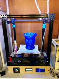
    Got some more construction done, It is essentially mechanically built.
    [​IMG]
    [​IMG]
    [​IMG]
     
    Muh_3d and Brian Totten like this.
  9. adamcooks

    adamcooks Well-Known
    Builder

    Joined:
    Nov 6, 2014
    Messages:
    244
    Likes Received:
    65
    Got my drivers set up tonight. I am using the 4988 blacks, to make them compatable with the mightyboard i had to solder them upside down. Needed to use some jumpers to access the trim pot. Jetguy's answer to my question about setting VREF. "If so, most of them use 0.4V Vref = 1A so just multiply your value in desired Amps times 0.4V= Vref. So 1.5A= 0.6V Vref , 0.8A for the extruder is 0.8*0.4V= 0.32V Vref
    8 days until moving truck arrives.....
     
    #39 adamcooks, Apr 7, 2015
    Last edited: Apr 7, 2015
  10. Joseph Ecker

    Builder

    Joined:
    Apr 5, 2015
    Messages:
    30
    Likes Received:
    3
    Hello,

    Would you have a link to someplace that describes the process of getting the 4988 drivers connected up to a mightyboard? Unclear about the "needed to use some jumpers to access the trim pot."

    I've been studying your design as well as the C-Bot...

    Thanks much
     
  11. adamcooks

    adamcooks Well-Known
    Builder

    Joined:
    Nov 6, 2014
    Messages:
    244
    Likes Received:
    65
    I'm not sure why these pics didn't attach the first time. Basically I used a m/f jumper to connect the driver to the MB. two of them, one on ground and one on VDD . Another jumper from the other ground to my DMM, aligator clipped. You measure the VREF at the pad that I circled. The worst part of the operation was having to power cycle inbetween drivers. DSC_0423.JPG DSC_0425.JPG DSC_0426.JPG a4988_pic.jpg
     
  12. adamcooks

    adamcooks Well-Known
    Builder

    Joined:
    Nov 6, 2014
    Messages:
    244
    Likes Received:
    65
    i thought i had posted this as well. remove the pin in the MS3 slot, then solder bridge to MS2. I should have rotated the inverted one to show the missing pin better. The close up in the post above shows that pretty well. DSC_0412.JPG
    [​IMG]
     
    #42 adamcooks, Apr 7, 2015
    Last edited: Jul 15, 2015
  13. Joseph Ecker

    Builder

    Joined:
    Apr 5, 2015
    Messages:
    30
    Likes Received:
    3
    Oh, so you hook up the driver with jumpers, adjust the trim-pot and then attach the driver to the mightyboard?

    I think I've got it :)

    Thank you very much for the great pics!
     
  14. Joseph Ecker

    Builder

    Joined:
    Apr 5, 2015
    Messages:
    30
    Likes Received:
    3
    on a side note, I think I have that exact same dmm... lol
     
  15. adamcooks

    adamcooks Well-Known
    Builder

    Joined:
    Nov 6, 2014
    Messages:
    244
    Likes Received:
    65
    That's interesting, I didn't read any explicit directions and I only stumbled onto that pad that I used. My screwdriver is ceramic, I don't think your method would have worked for me.
     
  16. adamcooks

    adamcooks Well-Known
    Builder

    Joined:
    Nov 6, 2014
    Messages:
    244
    Likes Received:
    65
    It appears that the clip the lead to the screwdriver is the preferred method. Learning every day for me.
    [​IMG]
    [​IMG]
    [​IMG]
    [​IMG]
    [​IMG]
     
    Mark Carew and Carl Feniak like this.
  17. runninfarmer

    runninfarmer Well-Known
    Builder

    Joined:
    Feb 22, 2015
    Messages:
    99
    Likes Received:
    48
    Nice lookin build! Is the build plate pretty stable and easy to balance? I'm thinking about implementing your 3 screw design in a build.
     
  18. adamcooks

    adamcooks Well-Known
    Builder

    Joined:
    Nov 6, 2014
    Messages:
    244
    Likes Received:
    65
    Adjusting the Z is fairly easy. Loosen the set screw on the pulley, rotate the lead screw, tighten set screw.

    The belt runs super smooth, but has not seen any electricity yet. I think my mbi style stepper cables are not compatible with these stepper. Moving truck comes tomorrow, ran out of build time.
     
  19. adamcooks

    adamcooks Well-Known
    Builder

    Joined:
    Nov 6, 2014
    Messages:
    244
    Likes Received:
    65
    Printe IMG_20150420_000214:nopm:.jpg IMG_20150419_220608.jpg d my first cube tonight. Borked my first stepper driver tonight. First print had some belt tension issues. I think my ssr for my heart bed is defective also. Full time on with no input signal. The HBP heats up very quickly.
     
    #49 adamcooks, Apr 20, 2015
    Last edited: Apr 20, 2015
  20. adamcooks

    adamcooks Well-Known
    Builder

    Joined:
    Nov 6, 2014
    Messages:
    244
    Likes Received:
    65
  21. hax0red

    hax0red New
    Builder

    Joined:
    Feb 26, 2015
    Messages:
    57
    Likes Received:
    14
    My 40 amp FOTEK SSR I purchased from Amazon also died within an hour or two of use. Let us know what you end up using for a replacement as I'm still using my Azteeg X5 directly for a 160mm heated bed.

    How do you like the MK8 extruder setup? Can you post the mount design? I'd like to give one a try since some of the Makerbot 2's print quality I've seen have been really great.
     
  22. adamcooks

    adamcooks Well-Known
    Builder

    Joined:
    Nov 6, 2014
    Messages:
    244
    Likes Received:
    65
    It turned out to be user error with my ssr, the output side is directional. + is input -is output side. Once I hooked it up properly it functioned fine.

    The mount for my extruder is just a universal dual extruder mounting plate, with a90 degree bend in it. I plan on replacing that with a aluminum right angle. Pretty easy mount. I will post some photos when I can, the bot is currently behind a wall of moved boxes.

    The short, all metal, stepped thermal barrier is the best in my opinion. You get actual retraction, and coupled with sailfish you get best print quality on8 bit. Driving one direct drive stepper around with two kysan's should be no trouble, my clone uses one .8A stepper to move my dual extruding carriage.p
     
  23. adamcooks

    adamcooks Well-Known
    Builder

    Joined:
    Nov 6, 2014
    Messages:
    244
    Likes Received:
    65
    [​IMG]
    First ugly no cooling fan PLA. was a sample of some pre lubricated stuff. Also, stepper motor was loose, every time it tried to change filament direction there was some deflection of the motor/filament drive. I have updated my to-do list

    To-Do List
    1. correct sag in HBP
    2. reprint shorter lead screw base, allowing clearance of cross-member
    3. model strain relief for gantry
    4. remodel gantry plate to accept extruder bracket better
    5. center rear leadscrew
     
  24. Carl Feniak

    Carl Feniak Journeyman
    Builder

    Joined:
    Mar 18, 2014
    Messages:
    654
    Likes Received:
    246
    One things you may want to do is put a cross beam under the center of your bed platform and install a spring off of it under the center of the bed. This might help with the sag you mentioned.
     
  25. adamcooks

    adamcooks Well-Known
    Builder

    Joined:
    Nov 6, 2014
    Messages:
    244
    Likes Received:
    65
    My plan with the HBP is to put a angle aluminum extrusion under it.
     
  26. adamcooks

    adamcooks Well-Known
    Builder

    Joined:
    Nov 6, 2014
    Messages:
    244
    Likes Received:
    65
    It has been a long slow process getting the last little bits straightened, and nit picky fine tuning. I finally have a nice flat plane to print on. I got the 300mm aluminum plate from lulzbot and mounted my PCB under it. I think i will use some 1mm ginopads to allow some expansion differences in the different materials. I need to make a support brace, holding the pcb against the bottom of the plate, the same sag that was causing me grief with the glass has returned, under the aluminum the only problem is low thermal conductivity. Luckily I just made nice with an employee at instructables who might be able to get me some flo-jet time. order up a k shaped brace to support the pcb and clear the thermister.

    next bug to squash, finding center offsets for slicer calibration. I need to run the centering script from repG, sailfish displays the information on the LCD. That information needs to go into S3D.
     
  27. Joseph Ecker

    Builder

    Joined:
    Apr 5, 2015
    Messages:
    30
    Likes Received:
    3
    Hi Adam,

    I'm really interested in your design for an 18x18 (~450mm*~450mm) printer. I'd be really interested in how you overcome the sag in the hbp. Do you think some sort of sag-leveling screw in the middle of the plate would work? I've been busy studying several of the corexy designs here and am preparing to nail down sources for the BOM.

    Thanks
     
  28. Zappo

    Zappo New
    Builder

    Joined:
    Nov 30, 2014
    Messages:
    16
    Likes Received:
    0
    Hi Adam,
    Some fine work being done here. Post some more detailed pics of your prints. Always good to have for comparisons.

    Folks have had pretty good luck with stacked belt loops. However the stacked loops can introduce a torque moment where the X carriage arm attaches to the Y rail, and at the X carriage itself for various acceleration directions. I see the main design goal of 3CB was to create a 3 screw version of Carl's C-Bot, but you also site tempo502 and Dan Newman's designs as inspiration.

    http://www.thingiverse.com/thing:393155 https://www.flickr.com/photos/d-newman/sets/72157645313526624/ http://www.thingiverse.com/thing:612857

    So totally not a criticism, interested in everyone's opinion. It seems like a single level belt system like dnewman's would offer advantages in that the belt/carriage moments would be reduced.

    The stacked belt meshes nicely with using a 20x40 X rail, but without having done any deflection calcs, I am having trouble believing that its extra sag rigidity is required vs a 20x20 section. Going to a 20x20 would reduce the X rail mass. Also the 20x40 increases the separation between the opposing carriage wheels, which reduces their effectiveness in countering carriage moments. We tend to stick all kinds of fans, leveling sensors, leds, cameras and other junk on the X carriage, so at the end of the day is it really tough to know where the center of mass will be.

    Flip side to this is I cannot find any discussions about the belt crossing scheme dnewman did. Dan obviously knows what he is doing and appears happy enough with the scheme, and from his flickr albums, has built a series of machines with this design. But these belts are in contact with each other, toothed side to smooth side. Are they a consumable like filament? Might create print artifacts or make noise?

    dnewman.jpg
    Another interesting design does a belt crossing on the half twist after the steppers so only the smooth belt sides might contact each other. Also guessing that with a few mm shift on where the belts ride on the pulleys, they would miss each other all together. http://forums.reprap.org/read.php?397,417806,page=1

    belt crossover.jpg

    So you could argue I am focused on a non-existent problem, but it seems like reducing arm mass and reducing unwanted moment asymmetries can only help, and might allow use of 3 wheeled carriages.
     
  29. adamcooks

    adamcooks Well-Known
    Builder

    Joined:
    Nov 6, 2014
    Messages:
    244
    Likes Received:
    65
    after a much too long hiatus on this project, I have begun to slowly creep froward with this project. I re-modeled the gantry plates, the front to hold the extruder bracket more securly, and the rear plate to include a anchor for a umbilical anti strain attachment point. I am going to mod enstop to anchor the other end. my umbilical will be supported by two pieces of 3mm filament or some CF rod I have in my kite bag.
    gantry back v2.png
    the gantry back prints in two pieces.
     

    Attached Files:

  30. adamcooks

    adamcooks Well-Known
    Builder

    Joined:
    Nov 6, 2014
    Messages:
    244
    Likes Received:
    65
    Some fine work being done here. Post some more detailed pics of your prints. Always good to have for comparisons.

    As soon as I get some good prints from it, I will put them up. I just got my HBP sag under control. My printer was sidelined for a few months with a cross country move. I just turned it on for the first time since april.

    I see the main design goal of 3CB was to create a 3 screw version of Carl's C-Bot, but you also site tempo502 and Dan Newman's designs as inspiration.

    It was their inspiration to use the mightyboard and sailfish as a firmware. My slicer just thinks my printer is a big plated Rep1. Any print on my rep1 sd card can be put into the 3C and press print.

    The stacked belt meshes nicely with using a 20x40 X rail, but without having done any deflection calcs, I am having trouble believing that its extra sag rigidity is required vs a 20x20 section. Going to a 20x20 would reduce the X rail mass. Also the 20x40 increases the separation between the opposing carriage wheels, which reduces their effectiveness in countering carriage moments. We tend to stick all kinds of fans, leveling sensors, leds, cameras and other junk on the X carriage, so at the end of the day is it really tough to know where the center of mass will be.

    The 20x40 really allows the belt to be hidden and run completely inside the rail. I had thoughts on acrylic side panels mounted on standoffs to allow the gantry bar cars to slide.


    Flip side to this is I cannot find any discussions about the belt crossing scheme dnewman did. Dan obviously knows what he is doing and appears happy enough with the scheme, and from his flickr albums, has built a series of machines with this design. But these belts are in contact with each other, toothed side to smooth side. Are they a consumable like filament? Might create print artifacts or make noise?

    I think the crossed belt idea was Jetguy's and he defends it vehemently, and most people just give up arguing with him. I have seen his 4'x4'x4' ulti replicator print with this setup. 1mm nozzle chewing from 10# spools of 3mm filament in ginormous vase mode, no artifacts. All three have reported no issues with belt wear. That top comes up on the google group from time to time with some regularity.


    So you could argue I am focused on a non-existent problem, but it seems like reducing arm mass and reducing unwanted moment asymmetries can only help, and might allow use of 3 wheeled carriages.

    I read an conversation between tempo and the creator of the bukito discussing this, I believe that it was in the context of a delta bot, but I think it would apply. I will have to search for it when I have a chance. They had decided that 3 wheels led to an imbalance in force and 4 was better, IIRC. I also use my clone as an example, a single crappy .8A stepper ( y axis ) moves the wight of 3 motors, two hot ends a dual carraige and all the related rods belts and such. 3C uses two 1.5A Keysan steppers, working together to move the gantry and a single extruder
     

Share This Page

  1. This site uses cookies to help personalise content, tailor your experience and to keep you logged in if you register.
    By continuing to use this site, you are consenting to our use of cookies.
    Dismiss Notice