Welcome to Our Community

Some features disabled for guests. Register Today.

Godzilla - a 3ft x 3ft CNC Router/Mill - Goals are strength, power and speed

Discussion in 'CNC Mills/Routers' started by stargeezer, Apr 7, 2015.

  1. stargeezer

    stargeezer Journeyman
    Builder

    Joined:
    Feb 20, 2015
    Messages:
    328
    Likes Received:
    117
  2. Serge E.

    Serge E. Journeyman
    Builder

    Joined:
    May 6, 2014
    Messages:
    730
    Likes Received:
    252
    :nailbite: Mega OX ... there may be rights on the name "Godzilla" (?) You could always name it gOXilla.

    Looking forward to following this build.
     
    stargeezer likes this.
  3. sgspenceley

    sgspenceley Veteran
    Builder

    Joined:
    May 27, 2014
    Messages:
    249
    Likes Received:
    292
    Good luck with the build. I look forward to reading more.
     
  4. Lee Whiteley

    Builder

    Joined:
    Sep 14, 2014
    Messages:
    23
    Likes Received:
    3
    Keep the information coming!!

    Lee
     
  5. stargeezer

    stargeezer Journeyman
    Builder

    Joined:
    Feb 20, 2015
    Messages:
    328
    Likes Received:
    117
    I LIKE OXilla!!

    Name Change time
     
  6. stargeezer

    stargeezer Journeyman
    Builder

    Joined:
    Feb 20, 2015
    Messages:
    328
    Likes Received:
    117
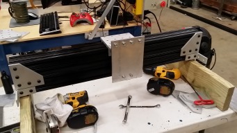
    Today I managed to get the side plates attached and you may notice that I have exchanged the triangular pieces I had placed near the ends of the gantry for rectangular pieces. These plates act as joining plates for the two 3x3 square extrusions that make up the gantry and I saw that the gantry slide hit the triangles 2" short of the side plates.

    Today also marked the first time I could move the gantry on it's rails. These 20mm rails are super smooth. So smooth that I'm second guessing the use of the 8020 linear bearings, which have much more loading on them and are far harder to slide. Now is the time for a decision, it seems to me.


    [​IMG]


    [​IMG]


    And here's the control panel where important things happen (that I don't understand :) ) Just Kidding! It's a bit sloppy, but I'm the one who has to work on it.

    [​IMG]

    4/9/15
    Larry
     
    #6 stargeezer, Apr 9, 2015
    Last edited: Apr 9, 2015
    GrayUK and sgspenceley like this.
  7. sgspenceley

    sgspenceley Veteran
    Builder

    Joined:
    May 27, 2014
    Messages:
    249
    Likes Received:
    292
    Larry, a great build thread, thank you for sharing. I know I was impressed with the linear bearings from China, good value for the money.
    Personally I would go for frame rigidity and smooth movement. CNC machines do lots of rapid changes in direction, so drag is not good. It will be very interesting to see it running under power and if it makes any difference.

    What size stepper motors do you plan to use?
     
  8. stargeezer

    stargeezer Journeyman
    Builder

    Joined:
    Feb 20, 2015
    Messages:
    328
    Likes Received:
    117
    I've got several sets to select from now, from NEMA 17's in 42 and 72 inoz, NEMA 23's in 120, 240 and 425 inoz. The control box I built will handle any of them and is way over kill for the 17's, but I'm inclined to go with the 425's just for the strength. I the gantry slide has a lot of drag compared to the lower 20mm bearings - they are like on air.

    I have another set of 20mm bearings that I could throw at it very quickly, but I'm really wanting to at least try the 8020 bearings. I should add that I've not lubed the 8020 bearings yet (dry graphite lube), so that may change everything when I do.
     
  9. sgspenceley

    sgspenceley Veteran
    Builder

    Joined:
    May 27, 2014
    Messages:
    249
    Likes Received:
    292
    If the 8020 bearings work well it will open up many new cost effective and simple solutions for builders. I looked at this solution I wondered if it would work, so I will watch with interest.

    Very good you have a selection of stepper motors and a backup plan! I hope the 8020 works well! With the 429 oz I'm guessing the 8020 slides will work well...
     
    #9 sgspenceley, Apr 9, 2015
    Last edited: Apr 9, 2015
  10. stargeezer

    stargeezer Journeyman
    Builder

    Joined:
    Feb 20, 2015
    Messages:
    328
    Likes Received:
    117
    One of the other forums I'm a member of is CNCZone.com and when I was planning this build I did a lot of searching for builders who may have tried these UHMW bearing material or specifically the 8020 bearings. I found a handful and of those every one had high praise of them. Conversely I was told by a large number of people that they would never work - none of these people had ever tried them. They just rejected them based on opinion. This was when I decided to try them and even though I have everything I need to replace the 8020 bearings with 20mm bearing and supported rails like I have used under the gantry.

    I had a conversation a little while ago with a 8020 factory rep who lives a few miles from me. He's going to stop by and check out my build in a couple days and evaluate how I've setup my gantry to see if I've properly adjusted them. I hope what I have is just an adjustment. According to the 8020 website, you simply back the screws that hold the UHMW pads in place a quarter turn and wack the assembly with a rubber mallet. It seems simple enough.
     
    GrayUK and sgspenceley like this.
  11. stargeezer

    stargeezer Journeyman
    Builder

    Joined:
    Feb 20, 2015
    Messages:
    328
    Likes Received:
    117
    Today a friend stopped by and we were debating the build. Since I was a bit frustrated with how the x axis tightened up as I bolted a mounting plate across the two parts of the slide. As soon as I loosened the plate, the sliding part became free. Close inspection revealed that the two bolts with washers on the lower sliding part were not allowing the mounting plate to completely seat in the lower frame due to the washers being too wide. This was the source of the binding and replacing the washers that were 1/8" narrower solved the problem.

    The 8020 linear sliding bearing is now super smooth and there is little difference in the load between it and the 20mm linear bearings and rail the y axis rides on.

    Today's update photo does not show a lot of change except the addition of cross pieces in the base, but the biggest change doesn't show in a photo.


    [​IMG]

    In this next photo you can see one of the four corner plates with a 3/8" hole where the leveling feet will be mounted.

    More to come in a couple days - Honey-do list item tomorrow will keep me out of the shop. But only for a day! ;)
    Larry
     
  12. stargeezer

    stargeezer Journeyman
    Builder

    Joined:
    Feb 20, 2015
    Messages:
    328
    Likes Received:
    117
    I've been making some progress the last few days. Here's some updated photos;

    [​IMG]

    [​IMG]

    The hole you see in the lower corner plate is to accommodate adjustable feet that you will see added later.

    The photo below was taken after the machine was removed from the low table where I made most of the major assembly and placed on the table where it will live. You might be able to just barely see the adjustable feet in this image. You can also see my long awaited Z axis assembly (yes, I wimped out and bought one instead of building that part - I feel so bad.....not!).

    [​IMG]

    Spindle is ON!!!

    [​IMG]

    Got to see it again? A different angle......

    [​IMG]

    Next up, Acme screws and steppers.
     
  13. sgspenceley

    sgspenceley Veteran
    Builder

    Joined:
    May 27, 2014
    Messages:
    249
    Likes Received:
    292
    Larry, It's looking great.... Love the spindle!
     
  14. stargeezer

    stargeezer Journeyman
    Builder

    Joined:
    Feb 20, 2015
    Messages:
    328
    Likes Received:
    117
    Thanks Steve. That 1.5kw water cooled spindle was the cause of the entire build (OK, I admit I wanted to build this in the first place). It was SO massive, I was afraid it was going to twist my little Shapeoko gantry into a pretzel. :)

    See ya. Off to work in the garage today!
    Larry
     
  15. sgspenceley

    sgspenceley Veteran
    Builder

    Joined:
    May 27, 2014
    Messages:
    249
    Likes Received:
    292
    It's funny how our CNC projects evolve and how one upgrade leads to another.

    It's also wonderful to see the creativity of people all trying to solve the same problem moving a spindle accurately along 3 axis.
     
  16. stargeezer

    stargeezer Journeyman
    Builder

    Joined:
    Feb 20, 2015
    Messages:
    328
    Likes Received:
    117
    Now the mechanical assembly is finished and the wiring is all but finished. Wiring is in need of being tided up and checked out. The first run of Mach 3 showed a bit of tightness in the Y axis so that needs sorted out too. Of course I need to post pics.
     
    sgspenceley likes this.
  17. stargeezer

    stargeezer Journeyman
    Builder

    Joined:
    Feb 20, 2015
    Messages:
    328
    Likes Received:
    117
    I suffered the first setback with my build this weekend when one of the acme screws the drive the X axis sheared off between the motor coupler and the bearing block. After I removed the stepper and broken coupler and end stub of the screw, I discovered that the screw was extremely hard to rotate. My immediate suspect was a bearing, but the real culprit turned out to be a problem with the spindle carriage - specifically the linear bearings/spindle plate had shifted out of alignment and twisted so much it was acting like a brake. As soon as I unbolted the carriage from the acme rod follower the screw became smooth when I rotated it by hand. As soon as I loosened the spindle from the carriage, the carriage slid smoothly across the axis.

    To correct the problem I have decided to do away with the 8020 linear "bearings, and replace them with fully supported 20mm linear rails and bearings. I soon had the carriage ore down the carriage and split the two 3x3 extrusions in order to get more distance between the bearings and rails. The carriage now glides much smoother.

    I have a new Acme rod already in order for another project that should be here in the morning. - diverted!

    Pics to follow soon.
     
  18. SaltyPaws

    SaltyPaws New
    Builder

    Joined:
    Jun 19, 2015
    Messages:
    3
    Likes Received:
    0
    Very nice CNC! :)

    Could you tell a bit more about how you get hold of your plates? How did you get the L shaped brackets machined?
     
  19. stargeezer

    stargeezer Journeyman
    Builder

    Joined:
    Feb 20, 2015
    Messages:
    328
    Likes Received:
    117
    Hi Salty Paws. I'm not to sure which brackets you mean, but all the L shaped connectors started out as 8020 parts. A LOT of these ended up being modified to meet whatever need I had.

    Side plates started out as a piece of 1/2"x10"x36" plate that I picked up on Ebay. Those were the perfect example of how the perfect tool for making a CNC router IS a CNC router. Due to my Shapeoko not being finished yet, I drilled and bored every hole with a drill press that was very carefully adjusted. I'm working on DXF files to reproduce all my plates now that the machine is finished. Maybe by next weekemd I'll have those up in the files area.

    The machine is now finished and works great! I'll be posting some pics tomorrow. Sorry that I had not updated sooner but there were several problems that cropped up as I was starting the tuning. For one thing the VFD blew up and I had to wait for a couple weeks for a replacement. Then I had some strange action on the Y axis that made no sense at all. It acted like RFI, but even after a complete rewire using very high quality shielded cable I still have the dancing steppers. Somebody on one of the CNC forums suggested that my driver might be the problem - I wish I could remember who it was because they were right! As soon as I replaced that everything started acting as it should.

    More to come later..........
     
  20. SaltyPaws

    SaltyPaws New
    Builder

    Joined:
    Jun 19, 2015
    Messages:
    3
    Likes Received:
    0
    Keep those pictures, files and build stories coming! :)

    Did you drill the 8020 L brackets yourself, or order them from 8020 pre drilled? I dont have access to a CNC router that can do aluminium (part of the reason I'd like to have one:eek:). I am thinking of ordering the plates machined from 8020, but I am a bit worried about the costs of this operation.
     
  21. stargeezer

    stargeezer Journeyman
    Builder

    Joined:
    Feb 20, 2015
    Messages:
    328
    Likes Received:
    117
    The 8020 brackets come with holes drilled to match the series of extrusion they mate to. For example, my build is based on the 15 series extrusions - that is that the size everything is based on multiples of 1.5". The extrusions I used for my gantry are 3"x3" and to complicate things a bit, 8020 makes heavy and light version of these larger extrusions. I used the heavy version, and wow is that 3x3x36 extrusion heavy!

    The extrusions used to build most of the Ox's you see are 20 series - but these are METRIC extrusions whose dimensions are based on a 20mm metric. You also need to think about how you are going to move your gantry around. If you are going to use belts like a low of the Ox builds, the V Rail that are sold here on OpenBuilds is the right choice. 8020 does not sell this extrusion.

    If you are opting for linear bearings, rails and feed screws of some type, your extrusion options are unlimited.

    There are a number of folks here that do cut Ox based plates for builders of these machines. If you inquire I'm certain somebody will sell you a very well made set of the plates you need to build a Ox for yourself.
     
    SaltyPaws likes this.
  22. SaltyPaws

    SaltyPaws New
    Builder

    Joined:
    Jun 19, 2015
    Messages:
    3
    Likes Received:
    0
    Hi Stargeezer. Thank you for the comprehensive reply. I was thinking of using the SBR30 linear rails, with 25 mm ball screws from the familiar seller on ebay. The hole space on the SBR30 series rails is 40 mm, so I could easily mount these on the 40 series extrusion, using the T slots. However, the hole space on the carts is 55 mm, and this does (not?) easily fit a 8020 bracket. You managed to nicely mount your linear rails to the extrusion, and also the cart to the L plate. The hole spacing on the cart is larger than the one on the rails, so please let me know how you managed to go about these connections.
     
  23. stargeezer

    stargeezer Journeyman
    Builder

    Joined:
    Feb 20, 2015
    Messages:
    328
    Likes Received:
    117
    Well gang, I'm passing the 98% mark with these photos. Shows the areas that have been questioned and I hope shows my "good enough for me" solutions. Along the way to this point it became very clear that there is more than one way to do any of this construction and still get a working end product. I now have enough spare parts to build another machine, or perhaps two. :)

    I also have a "add on table" under construction that will allow me to double the length of the Y axis. By changing the acme screws, the lower frame rails that the linear rails are mounted to and replacing them with longer acme screws, linear rails and a frame extension, I'll be able to double the size, using parts I already have in my garage. I think it would take about a hour to make the changeover.

    Along the way I experimented with three different stepper types before going back to the 425 ozin pieces I started with. You might notice the VFD that beside the CNC. That was the 2nd VFD that was used. The first one became a casualty of my early testing. The post mortem showed aluminum shards shorting out the regulator board, which caused a violent disruption and internal arcing from the VFD. It sounded just like welding with a mig. The little VFD was just in the wrong place as I was test cutting some aluminum. The chips evidently entered the ventilation slots you can see on top and on the sides of the VFD when the cutter moved to just the right angle. I now have the VFD mounted with a shield around it to block the chips. Expensive lesson buddy.

    I started out using 8020 brackets everyplace I needed to mount something. Some of this 1/4" thick brackets were just not strong enough to do the job. They would flex as the gantry changed direction acting like a spring, bouncing slightly. I replaced a number of these with simple, 1 /2 x 1 1/2 x 5" aluminum bars, that I cut to fit.

    Another change I made shortly after I got the machine functional was to replace the single start acme screws with 5 start acme screws. These give a movement of 1/2" per revolution! They really helped by lowering the RPM's I was asking them to produce with the 10 turns per inch.

    Things still needed done;
    1. Dust shoe
    2. fine tuning the gantry (its just a bit off level)
    3. lights under the gantry and spindle
    4. Chip shields to protect computer, monitor, keyboard and OP :)
    5. jog controller on left side
    6. build set of drawers to mount below CNC. For tooling
    7. Buy lots of wood.
    More to follow.

    Please feel free to ask any questions.

    Larry


    [​IMG]


    [​IMG]

    [​IMG]


    [​IMG]


    [​IMG]

    And how best to end this photo essay except with an appearance by His Majesty (actual title). Please check your "humor bone" and read below before commenting.

    [​IMG]
    For those not familiar with the sculpture, it was contracted as a rendition of George Washington in the "Heroic Style" that was gripping Europe at the time. It currently resides in the basement of the Smithsonian Fine Arts building. I'm uncertain if its actually on display or not. To me, as a artist, placing the head of our first black president on the Heroic body of our first president seemed somehow "interesting". This has been remarkably well received and displayed in several art expositions. I offer it here to express how this build has progressed, starting with great promise and heroic fanfare, passing through periods of excitement and more than a few failed experiments, coming eventually to a point where the construction is finished and all that's left is promises of future success (we hope).

    Larry
     
    GrayUK likes this.
  24. stargeezer

    stargeezer Journeyman
    Builder

    Joined:
    Feb 20, 2015
    Messages:
    328
    Likes Received:
    117
    We're voting on it??? :) My desire is always to make people think and consider how all things are interwoven and use humor as much as possible. As a full time artist, I'm always looking for inspiration and the opportunity to present what's going on in my life. I don't ask that others accept or agree with it, just think about why I present it. In this case, building my Oxilla has been exactly as I described it and I think the message is valid. Like a new born baby, the completion of my Oxilla is not the end of the adventure, it's the beginning. Like the completion of any project the founding of our nation was the birth of a great experiment, and in many ways the election of our first black president was as historic as President Washington was. Just as the nation had great promise with that first election and presidency our current leader is presenting us with a promise.

    All that said, what did you think about the Oxilla?
     
  25. Florian Bauereisen

    Florian Bauereisen Well-Known
    Builder

    Joined:
    Feb 24, 2014
    Messages:
    188
    Likes Received:
    60
    .....
    All that said, what did you think about the Oxilla?


    HI,
    nice effort - but since you asked:
    your desire had been a strong machine but to my eye you have missed a couple of chances:
    connect the horizontal x-axis extrusions in order to minimise bending by
    -the weigth of spindle
    -cutting or rather drilling forces.
    a say 10mm aluminum plate will do nicely. Use a wooden plate if you want to minimise vibrations..

    Space your lower wagons as far appart as possible to minimise tilting aound your y-axis... rule of thumb is 2:3 meaning 3 high needing at least 2 spacing appart.
    While at it- try getting the spindle or rather its cutting bit right in line of the wagon on y. (no overhang)

    Use at least supported rails on Z, as these unsupported ones will bend as soon you are trying to mill something harder than lightply. It will be most noticable when milling in +/- 45 deg. to x/y. or i.g. a circle.
    Just take two straws and connect them at their ends - still they will twist easylie.
    Supported rails would have been a far better choice.

    Another mod that comes almost for free is to mount the "Wagons"/"cars" upon your x-z plate while mounting the supported rails onto your z-plate. (just mirrored to your setup).
    This will
    -stiffen your z-plate aditionally
    -give you a better lever onto your wagons - so less flex. (at least when spinlde is higher up- like milling in a vice)

    Your side plates will be the weak part in your setup. They look a bit on the flimsy side to me and might flex when accellerating or stopping apruptly on x.
    Just screw on some alum. brackets.

    Once you stiffen one part than the next will be the wakest one...in the end the machine will weight tons -LOL
    After stiffening up your side plates the wagons on your supported rails will be the weak link - they will tend to "roll" aound the rail when going hard on x...
    so in the end the square type of rails will give the best results..

    While building a cnc its generally important to watch out for levers. lenght and hights always factor in tripple so do not build a generous z when you do not intend to use it. keep your machine slim on x when you do not whish to use full sice wood-plates anyway....
    Keep forces as close to the wagons as possilbe.

    A couple of this tips are generally meant and not for your setup specifically but i thought i would give a complete answer

    Just food for thought

    greets from munich germany

    Flo
     
    #25 Florian Bauereisen, Jul 16, 2015
    Last edited: Jul 16, 2015
  26. stargeezer

    stargeezer Journeyman
    Builder

    Joined:
    Feb 20, 2015
    Messages:
    328
    Likes Received:
    117
    Thanks Flo. I'll consider several of your points, but disagree that the 1/2" (13mm) side plates are flimsy. I did start out with the horizontal extrusions (that are 75mm square) stacked, but discovered that I had flex in the coupler that linked the spindle to the leadscrew and placing it between the extrusions solved that. The linear rails in the Z axis are 20mm and are 8" long. I know there's a lot of tool pressure, so I'll keep a eye on that. I've been cutting aluminum and haven't seen it flexing yet.

    The pics might be a bit deceiving but the sideplates are 10 inches wide and the upper linear rail is 12" above the y axis linear rail carts. So the x axis extrusions are a total of 6" out of 12" of contact. I intend to add a plate linking the extrusions as soon as it arrives. I didn't think about using wood for it, it may be added until the aluminum plate comes in.

    I totally agree about the spindle sticking out so much, but at this point I'm just not to certain how to eliminate this problem without starting from scratch.

    On to better things. Bavaria. That jewel of Germany! We lived for three years outside of Bamberg. It was my last duty station before my retirement. We did a lot of touring while we were there and enjoyed Munchen whenever possible.

    Best to you,
    Larry
     
  27. Florian Bauereisen

    Florian Bauereisen Well-Known
    Builder

    Joined:
    Feb 24, 2014
    Messages:
    188
    Likes Received:
    60
    Sorry i misjudged the pics then. 13 mm seems ok.
    But still in relation...
    as mentioned before, first one upgrades the x-beam, now the side plates are the weak point, after stiffening these the weak link moves toward the wagons...
    ending in 1-3 ton machines -LOL
    Well as hobbyists we need not take everything that important but it is good to understand the principle and design acordingly.

    Ever want to come back? gimme a shout.

    greets

    flo
     
  28. stargeezer

    stargeezer Journeyman
    Builder

    Joined:
    Feb 20, 2015
    Messages:
    328
    Likes Received:
    117
    I'd love to come back! But I'm now wheelchair bound and not exactly the man I was 30 years ago. :)
     
  29. Paruk

    Paruk Journeyman
    Builder

    Joined:
    Jul 13, 2014
    Messages:
    397
    Likes Received:
    149
    It would be fascinating if you were!;)
     

Share This Page

  1. This site uses cookies to help personalise content, tailor your experience and to keep you logged in if you register.
    By continuing to use this site, you are consenting to our use of cookies.
    Dismiss Notice