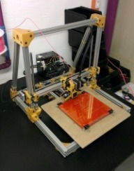
Here is a X-axis Plate for use with the Openbuilds 8mm nut block. I will try and draw up the Y-axis plate for the nut block after work tomorrow.
The ends don't use the OB nut plate, just a socket to hold bearings that hold the 8mm shaft. The threaded part fits the X-carriage (in the middle.
What i meant to right was just looking at modifying the axis parts to use the nut plate. in otherwords the backwardy and forwardy things that move the tool and bed, too and throw.
Here you go, New X-axis plate for use with the Openbuilds nut plate. ( The X-axis plate holds the nut and moves the tool head left and right in this case a extruder) If this is what you are looking to do, I can draw up a Y-axis for you as well (Y-axis plate mounts the nut to the heat bed and moves it front to back )
This is exactly what I am looking ToDo Yes please do draw that up for me thanks Just ordered my parts from Ozznest all the OpenBuilds components
Here is the Y-axis plate... Let me know how they work out as I don't have any nut plates on hand to test print / fit them..
Another one to keep a eye on is Kevin Smith's build. He is using Standard TR8*8 Screws as well. Plus a number of other upgrade's like a Kraken hotend. Not sure if he posted his files any where I can not seem to find them but he has a number of photos. https://plus.google.com/wm/1/101384566588558800558/posts
Is there really any downside to using standard TR8*8 screws instead of the 10 Start 25mm pitch screws, other than your X and Y movements being slower? Does anyone have any experience with the TR8*20 or TR8*12 threaded rod steppers from Robotdigg. I'm really interested in this design, just trying to figure out which direction I want to go with lead screws; just use TR8*8 on all axes, or try the TR8*12 or TR8*20 on the X & Y. From reading through this thread, the price and headache of sourcing a 10 start 25mm pitch screw seems insane..
Hey Could i get X-Axis ends with Nutplate add on. I have some weird ebay nuts that don't quite work. This would also make it more accessible to british people who don't have access to robodigg
Hi It could be my volcano setup but these need to fit a little larger on the centre hole in order to work not much at all probably around 0.2mm [0.1mm +/- NIL ] in order to fit. Can I ask you a favour i've be struggling all day to modify the x-axis ends. I'm used to Inventor so sketchup isnt really my thing hence the struggle. I was wondering weather you could quickly modify the ends to fit this nut http://www.ebay.co.uk/itm/131456875216?_trksid=p2060353.m1438.l2649&ssPageName=STRK:MEBIDX:IT I don't imagine it would take an experienced person long at all. and this is really just the final two parts that are holding the build up. If the bearing holder on the X-axis end. could have it's bearing holder made bigger using the 608zz Bearing that would also be great Thanks John.
Hi everybody, I'm just want to ask do you still believes this printer will cost 700 dollars after almost a year? Thanks, Adriano Bertoni
Johnr24 -- I will work on the x-axis ends for that lead screw when i get home, only have my mobile and linux laptop with me right now.. Florian -- Looks great! I am not sure about the OB nut I have not used any yet. Jaspion3d -- For the base frame and printed parts needed $700 is about right, With electronics / hot end / heat bed / lead screws / shipping / power supply / glass / misc parts nuts n bolts / ect. it can go up. I have about $1400-1700 into mine already. However I have to pay shipping on almost everything I buy ( lack of local stores in such a small community ) I also went with a usa supplier for all my electronics not ebay / china. ( aliexpress / alibaba black list my state ) So I could have saved a huge chunk there. Another thing I learned with this build is dont buy nuts and botls one at a time as you need them locally that really eats $ and time. I already learned my lesson on that one and ordered a small stock for my next builds
Thanks Kyo. Do you have a list of the things I will need to have to build such printer like yours? Thanks Jaspion
I made some that work with my brass ebay screws. I translated all of the measurements from sketch up into autodesk inventor I have included. the autodesk Inventor files for this as well as STLs. STEPs and others available on request.
I followed the US b.o.m provided in the files tab. With changes to the Heat bed and electronics, I went with Makerfarm 12in pcb heat bed and full ramps 1.4 kit with a full graphics lcd. Along with the X and Y axis leadscrews, I went with machined 12mm dia 6 start 18mm lead with nuts. I apologize, I completely forgot to do that after I got home. Glad to see you were able to get it done..
Sorry if this has been asked before, but are there any compatible leadscrews on mcmaster-carr that would work with this printer? I'd really like to build one, but I am having trouble finding the 10 start 25mm pitch leadscrew. I guess my main question is, does it matter if the leadscrew is a 1/2" diameter and only have 5 starts?
well...that is sorta true...depending on the screws and nuts, you might have to redesign some of the parts and attachment methods. Luckily, some of them have been shared as they were created by other users who got stuck trying to figure this all out.
Time to pick up the pieces of a failed build and get it back on track. I'm trying to get back to school on top of a full time job (that I've finally been able to trim hours down to 50+ week) and get other students interested in 3D printing. I had a 14" X 14" X 14" printer named "Igor". It was an OK printer, but needed work to improve beyond just acceptable prints. Lots of newbie mistakes and in the early days I didn't have a reliable hot end. We had started a printer club on campus and were making some decent progress. There was a senior project team that didn't have a project and decided to build a printer. Since Igor was needing some real engineering I pitched in Igor for parts and let the team start working on their own design using Igor's bones and various bits. I don't think I've ever seen as complete a senior project fail as theirs. 8 months into a 9 month class and I wander into the lab to check progress. They "finally" have the frame mostly together. I ask where the motor mounts were, and they answer with "yeah, guess we should figure that out". They passed the class. But what should have been an easy build is just a pile of chopped up 80/20 and random bits. It was supposed to be the anchor machine for the 3D printing lab we are pulling together on campus. So I picked up the debris and did a couple of quick iterations to try and get the thing finished. I had been fighting with motion of the bed in the Y axis. We had decided to make a moving bed design with a 14" X 20" build area. Z is supposed to be somewhere in the range of 20" to 24". This meant the bed would be fairly heavy and using linear bearings and Thompson rod didn't work all that well. Too much sag in the middle. I switched to bearings with low friction nylon pads ridding on top of 80/20. Belt driven with a beefy NEMA23 motor. But I couldn't get past far too high an amount of friction just moving the bed by hand, let alone with a decent sized part on it. I'd been searching for an alternative when I ran across openbuilds and started poking around in the forums. It looks like I should be able to adapt the Lautr3k to what we are striving for. I picked up the Makerfarm 12" iV3 to see how the v-slot works and I'm pretty happy with it (only up and running for a few days so far). So I have a few questions if anyone would like to help me out: How difficult would it be to scale the NEMA17 parts to NEMA23? My 80/20 is 1" X 1" and 1" X 2". Looks like I'd also need those parts scaled. I have a Kraken set-up that I'm probably going to upgrade to Volcano tips. That way I can cut down on build times for the large parts. I'd like to see if there is a quick-change option for the X gantry hot end mount to let us swap back and forth depending on the print needs. We are also trying to work with the NinjaFlex materials, so I need to make sure I have a dual setup for a direct drive option on at least one of the nozzles ( means a second mount next to the Kraken). Sadly, I've spent more than a bit on Acme threaded rod from McMaster-Carr. All single start. :-( I'm willing to spend more for threaded rod for X and Y, but I'm pretty firm about not sourcing anything from China. I try and buy local whenever possible. So I've seen lots of discussion on the rods, but the link in the BOM doesn't seem to be working. I'll dig a bit more in the thread and see if I can find the links again. Has anyone gotten gear from Misumi? I keep getting adverts from them, but I just haven't had a lot of time to dig through their site. I'm not a CAD monkey at all. I'll be downloading Sketchup and installing it on my home machine. But it really isn't something I'm good at. The X carriage will need clearance on both sides but I'm going to try and limit the width of the machine to 32". I'm still trying to wrap my head around how to place the extruders and the motor for the stage to keep from loosing build area. But that is probably more than I should be asking at this stage anyway. All help is greatly appreciated. Just feels like I've finally found a workable solution that might get us printing by the start of Fall term. Thanks, Mike
Hello Mike, welcome aboard. I am only a heat bed mount away from getting my lautr3k based printer "Fina" up and running.. I think it is a great base that accepts mods well. I am also running a Makerfarm I3V 10". I think you will be very happy with yours! I have well over 1,000 hrs of solid run time on mine and it is still going strong will be coming out for a tear down and rebuild into a enclosure here soon. I order a lot from Misumi, once you get a hang of the site they have some great products at good prices and offer cutting and machining at no extra cost. They have always cut my parts exactly to spec and turn around time has been on time. Can not recommend them enough. If upgrading to nema 23 motors. The X axis parts that mount the Z axis lead screw nut will need to be remodelled. The nema 23 being larger will place the motor shaft closer to the inside of the printer then a nema 17 and the lead screw and nut would no longer align with the mount on the X axis parts. For the Y axis I would double check the bed will clear the larger motor. The weight of a nema 23 hanging off one side of the X axis going up and down may cause problems but i am not sure. I look forward to seeing your build, sounds like it is going to be one large printer. I started a build with a similar bed size ( 15 x 24 x 6 tall ) Parts of It sit in the corner staring at me, reminding me of my failure lol I will get back to it one day, It had bed sag issues at 24in wide. It was either flat and heavy or light and saggy. never did find a ideal solution..
Yeah, I like what I've seen so far on the Makefarm. I have it at work at the moment, but there is a terrible A/C draft in the corner I'm trying to work in. First ABS parts warped pretty bad. I've been calling the lab "Ice Station Zebra". :-/ But I just cleared room in the apartment, and the extra 80/20 that is laying around should make a quick enclosure and filament stand without a lot of effort. I'll be sure to post some pics of both printers as I move forward. I also have some of Monster before I tore it down today. Feels good to finally start making some progress. I'd like to keep the 23's if I can. They are 48V monsters that really crank the torque. They are from a large format 2d solid ink printer (Xerox 9300 series). They are used to generate 2100N of force to press the ink into the paper, though that was through a gear system. I was planning on running them at 24V but I'm beginning to wonder if maybe I should use a 48V supply instead. The motor has an encoder on it, but I don't remember if we have to specs to actually use the output. The motor body is roughly 4" deep. Maybe counter-balance the weight on the other side? I'm thinking that if I can make the gantry generic enough we may be able to use it for light CNC work or put some paste extruders on it. There are several of the girls that really want a chocolate printer.
Has anyone ever done this design in Inventor or Solidworks. I use inventor and am interested in making this build using the RobotDigg stepper mounted screws and it would be preferable to me to lay it out in Inventor to check all the lengths first. I have the stl files and I could just lay it out from there, but I thought if someone had already done it, then it would save some time.
I just started to draw up my next lautr3k inspired build in Fusion 360 Ultimate ( free for makers ) I have only done two parts as of yet. So far I am liking it. Started to use it so I can learn the cad/cam functions it offers prior to a upcoming cnc router and mill build. Can not beat the free built in 5-axis hsm cam. I look forward to what you draw up.
It will be a few weeks before I have the time to devote to modeling the new parts. Inventor Pro can convert the stl files back into part files, so that part is easy. Once I get it done I will try to get you a copy of the finished assembly.
You designed a great printer skarab. After a few days tuning my drivers / motors and dialing in my firmware, I am starting to get some great prints! Thanks again for sharing so all of us can build our own.. Cain't wait to try some abs.. PLA Nozzle 190 *c Glass Bed ( with tape no heat bed ) 60 mm/s 0.35 First Layer Height 0.2 Layer Height 0% Infill Pink Panther ( 20% Hexagon Infill For 3DBenchy ) 3 perimeter layers