Welcome to Our Community

Some features disabled for guests. Register Today.

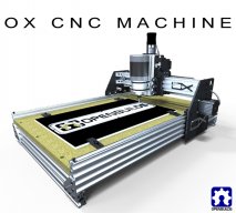
OpenBuilds OX CNC Machine

Discussion in 'CNC Mills/Routers' started by Mark Carew, Dec 15, 2013.

  1. lawrenceyy

    Builder

    Joined:
    Jun 14, 2015
    Messages:
    8
    Likes Received:
    0
    Hey Mark Carew,

    Great videos, you've inspired me to build my own CNC router. I'll probably build the bigger version. I only recently discovered this website, but the aluminum beams and components look really awesome. And since there is free shipping this weekend, this is the perfect time for me to order all my parts.

    I just had a few question for you:

    1. I did buy a small C-beam linear actuator bundle from the parts store the other day. I put it together and it works great. If I swap out the C-beam gantry plate for the X shape gantry plate on the Z mechanism of the OX, would that sufficiently replace the current Z mechanism (20x60 v-slot riding between 6 wheels)?

    2. In theory, could I use a C-beam to replace the two side-by-side 20x60 V-slots that make up the X axis rail? Would that be more precise? And even crazier, could we just use a C-beam linear actuator for X axis motion? So we would have a C-beam gantry to C-beam gantry connection where X and Z rails meet? You would have less stuff sitting on the X rail, but moment might be an issue for the gantry plate. And would speed be an issue (I have not tested my linear actuator yet since the stepper hat for my raspberry pi could not supply enough amperage to drive the motor)?

    Hopefully you can respond before midnight.

    Thanks,

    Lawrence
     
  2. Mark Carew

    Mark Carew OpenBuilds Team
    Staff Member Moderator Builder Resident Builder

    Joined:
    Jun 28, 2013
    Messages:
    2,762
    Likes Received:
    2,446
    Hello @lawrenceyy
    Thank you for contacting us and thank you for your support
    The Z axis of the OX build uses 60mm wide V-Slot and the C-Beam is 80mm wide so that would not work for that plate.
    However you can make a Z axis like your thinking you would just need to use a plate like the V-Slot universal gantry plate that can accept the 80mm wide C-Beam.
    Take a look at this build by CWidt CAndC - CNC Machine
    http://www.openbuilds.com/builds/openbuilds-candc-cnc-machine.2086/
    He has done a great job to show examples of how some of the axis could be built using C-Beam.
    I don't think you will need to worry about the speed at all, there will be plenty for a CNC router.
    I hope this helps. We wish you all the best with your build and again thank you.
    Mark
     
  3. Torslen

    Torslen New
    Builder

    Joined:
    Jun 15, 2015
    Messages:
    4
    Likes Received:
    0
    Hello Mark Carew,

    This looks like a very professional build and comes at a much better price than other builds that are commercially available. I have been very excited to fill out an order for parts and start building my own. I have two questions however.

    For my build I am planning on making a larger cutting bed so I am using 20x80 extrusions that are 1500mm long for the x axis and 20x40 extrusions that are 1000mm long for the Y axis so the bed will be approximately 1500mm x 1000mm. Will a bed that size maintain the strength needed for a stiff structure and accurate cuts?

    Secondly the only piece that I have not been able to source is the Nut Block for 8mm Metric Acme Lead Screw. It is currently out of stock and I was wondering if there is an expected time frame for when it will be back in stock or if there is an alternative solution for completing the linear rail system for the z axis.

    Thank you for all the time, resources and information you have provided on the OpenBuilds discussions and in other videos. It makes this experience much easier.

    Cheers,

    Thomas
     
  4. dddman

    dddman Journeyman
    Builder

    Joined:
    Mar 2, 2014
    Messages:
    468
    Likes Received:
    187
  5. Torslen

    Torslen New
    Builder

    Joined:
    Jun 15, 2015
    Messages:
    4
    Likes Received:
    0
  6. lawrenceyy

    Builder

    Joined:
    Jun 14, 2015
    Messages:
    8
    Likes Received:
    0
    Hey @Mark Carew ,

    Thanks for your response before, I decided that I would just build the Z with a V slot like you did. I've ordered all the parts and can't wait to start building (those are some really expensive wheels though).

    One question I have is in regard to the Y motors. In your video you connect the two motors to the same wires coming out of the board. Does sharing the same output have any adverse implications to the steppers' performance? Does the amperage get split? Something electrical must be split 50-50, right?

    And what is the best way to cut down theses V slots to size? How do we deal with error and wiggle room?

    Thanks.
     
    #2526 lawrenceyy, Jun 20, 2015
    Last edited: Jun 20, 2015
  7. Mark Carew

    Mark Carew OpenBuilds Team
    Staff Member Moderator Builder Resident Builder

    Joined:
    Jun 28, 2013
    Messages:
    2,762
    Likes Received:
    2,446
    Hello @lawrenceyy
    OpenBuilds wheels are individually lathed to insure they are as accurate unlike so there is a cost factor there.
    As long as you are using the same motors you should be fine. I do this for many of my builds without any noticeable issues.
    V-Slot comes a little longer 3-4mm to allow for the width of a saw blade for say when cutting in half.
    Here is a link to a thread about easy ways for cutting V-Slot
    http://www.openbuilds.com/threads/cutting-aluminum-extrusion.20/
    Hope this helps, have fun with your build. :thumbsup:
    Mark
     
  8. John Eriksson

    Builder

    Joined:
    Jun 9, 2015
    Messages:
    4
    Likes Received:
    4
    Hello all, I am another newbie, and have ordered my Ox kit from Melbourne.
    I first thought of building a robot but soon discovered most are just toys, then I found the Openbuilds site, so the idea of building the Ox was borne.
    Now comes the (hopefully short) wait for the kit to arrive. I have gone with the Nema 23 and 17 motors, and have ordered a 4 axis TB6600 controller. I think that running 2 Nema23s in parallel off one chip might be asking for trouble. In the meantime, while awaiting for bits and pieces to arrive I am reading up on the experiences others have had with this project.
    Roll on the start of construction!!!
     
    GrayUK and Joe Santarsiero like this.
  9. John Eriksson

    Builder

    Joined:
    Jun 9, 2015
    Messages:
    4
    Likes Received:
    4
    I am looking for some details on slaving the two Y axis steppers using the Grbl controller but cannot find any reference. Everything leads back to the Mach3 controller, but no mention of the Grbl.
    Does this mean I will have to outlay another couple of hundred dollars for a single Mach3 hobby license? (Kind of makes it difficult when the desktop is in the study and the machine will be in the shed as this will require two licenses.)
    I don't want to have to run both steppers off the one chip.
    Has anyone else slaved the steppers using one of the free open source controllers?
     
  10. Joe Santarsiero

    Joe Santarsiero OB addict
    Staff Member Moderator Builder

    Joined:
    Oct 30, 2014
    Messages:
    902
    Likes Received:
    196
    Hey John, I think this is going to be handled on the hardware controller end. Any code received from the grbl control software will translate to both motors by the hardware through hardware setting or by using the same driver. Mach will send step and direction to two separate drivers if a slave axis is designated on the software side of things.
    On another note, mach3 can be installed on multiple machines with one license. Mach4 cannot.

    Joe
     
  11. Rick 2.0

    Rick 2.0 OpenBuilds Team
    Staff Member Moderator Builder Resident Builder

    Joined:
    Dec 20, 2013
    Messages:
    2,898
    Likes Received:
    1,556
    Which Grbl controller? If you ordered a 4 axis TB6600, you are not using a Grbl controller, you are using a controller which requires Mach3. It is also capable of running 4 separate steppers so there is no need to double tap a driver.

    If you are looking for a cheap Grbl controller, consider the TinyG controller as it also has 4 axis compatibility (i.e. 4 driver connections).
     
    Joe Santarsiero likes this.
  12. Josh B

    Josh B Well-Known
    Builder

    Joined:
    Nov 4, 2014
    Messages:
    116
    Likes Received:
    42
    After many hours of tweaking:confused:, head scratching (banging):banghead:, and a few cold beverages:cool:, my OX-alike is cutting like butta! Thought I would share some photos of 1/9th scale P40N fuselage former's cut by the Ox-alike. These are cut out of 1/16" birch ply using a 1/16" end mill at
    26 in/min or 660 mm/min. Couldn't be happier! Thanks again, Mark Carew, for a great design. And thanks to the countless others who provided loads of technical help. This is awesome, no more buying 100 count packs of #11 blades:thumbsup:...
     

    Attached Files:

  13. Mark Carew

    Mark Carew OpenBuilds Team
    Staff Member Moderator Builder Resident Builder

    Joined:
    Jun 28, 2013
    Messages:
    2,762
    Likes Received:
    2,446
    Well done @Josh B ! That nested sheet looks amazing and really shows the accuracy for these kinds of projects that can be achieved on these OX style CNC machines. Love it, thank you for sharing. :thumbsup:
     
  14. Josh B

    Josh B Well-Known
    Builder

    Joined:
    Nov 4, 2014
    Messages:
    116
    Likes Received:
    42
    Thanks Mark Carew. If I had just a tad bit more patience, i think I could have fit a couple more pieces on that 12"x 24" sheet. I do need to clarify that I did not cut all of them in one cutting session. I believe that sheet was done in 8 separate cutting sessions, about 23 minutes each. That's the beauty of using Sketchucam in SU 2015, I just add in 2 or 3 pieces as I go, leaving the ply stuck to the spoiler board. Why so many separate cut files? Because I have a 5 yr old son and a 2 yr old daughter....you know the story.
     
  15. Mark Carew

    Mark Carew OpenBuilds Team
    Staff Member Moderator Builder Resident Builder

    Joined:
    Jun 28, 2013
    Messages:
    2,762
    Likes Received:
    2,446
    Also be sure to check out the g-code joiner that David added it may be helpful for your set up.
    Yes yes we do :)
    I turned out great and again I thank you for sharing this. We hope to have a media section for each user to share pics of their projects soon here on OpenBuilds and this would be perfect for that.
    Mark
     
    #2535 Mark Carew, Jun 25, 2015
    Last edited: Jun 25, 2015
  16. davidbrowne

    Builder

    Joined:
    Jul 25, 2014
    Messages:
    30
    Likes Received:
    20
    I'm having too much trouble with my cnc xpro drivers and thought I might pick up a set of TB6600 drivers
    from ebay. The prices vary quite a bit and my funds are limited, so can anyone suggest which drivers to get or which to avoid. I know some people have problems with the amount of torque they get out of them, but I only require 2.4 amps so thought running a 5 amp driver at half its rating should avoid any problems with overheating. There must be others who can also profit from past experiences of old hands.
     
  17. cgfandrich

    Builder

    Joined:
    Jun 6, 2015
    Messages:
    2
    Likes Received:
    0
    It's hard to tell if anyone has mentioned this in 87 pages of comments, so I apologize if it's already been asked ...

    The Parts List says you need 17 1/4" spacers but the OXCalculator spreadsheet says 19. I can see how 19 works:
    4 for each Y gantry plate (1 per wheel on top row) = 8
    3 for the Z plate (1 per wheel on one side) = 3
    6 for the top 2 sets of wheels on the X plate (3 per set) = 6
    2 for the bottom 2 sets of wheels on the X plate (1 per set) = 2
    8+3+6+2 = 19

    Is there another way to build this with 17 1/4" spacers? Am I missing something? ... apart from 2 spacers :)
     
  18. bowlie1010

    Builder

    Joined:
    Dec 15, 2014
    Messages:
    1
    Likes Received:
    0
    I believe you do need 19, not 17.
    I placed an order recently for wheel kits, spacers etc to get my machine build started. Only to come up short on the 1/4" spacers. Luckily I had ordered the 1/8" spacers for the rest of the build, so I used four of those instead :/
     
  19. cgfandrich

    Builder

    Joined:
    Jun 6, 2015
    Messages:
    2
    Likes Received:
    0
    Thanks for the suggestion. That should work - and I'll use some of the extra precision shims I have to space the x motor off the plate.
     
  20. Torslen

    Torslen New
    Builder

    Joined:
    Jun 15, 2015
    Messages:
    4
    Likes Received:
    0
    I have been trying to find dimensions for the Gantry Plates that need to be cut. I have access to a machine to cut them myself but I don't have the dimensions. The "V-Slot OX_Build_81_DXF Plates.dxf" file opens up in my AutoDesk AutoCAD 2015 program but doesn't contain any dimensions. Could I be provided with the files needed to cut the Gantry Plates?
     
  21. Rick 2.0

    Rick 2.0 OpenBuilds Team
    Staff Member Moderator Builder Resident Builder

    Joined:
    Dec 20, 2013
    Messages:
    2,898
    Likes Received:
    1,556
    @Torslen, the DXF files are in millimeters and are to scale. The only really critical spacing is the center/center of the opposing wheels. At the 80mm V-slot the spacing is 99.8 and at the 60mm V-slot the spacing is 79.8 (i.e. section depth + 19.8mm). Plates shown in the Sketchup files are also correct.
     
    Mark Carew likes this.
  22. Torslen

    Torslen New
    Builder

    Joined:
    Jun 15, 2015
    Messages:
    4
    Likes Received:
    0
    Perfect Thank you!
     
  23. Jonny Norris

    Jonny Norris Well-Known
    Builder

    Joined:
    Aug 17, 2014
    Messages:
    491
    Likes Received:
    95
    Okay think I'll explain this one more time for people that have already read this and I hope others will pass on this info. From personal experience the toshiba drivers don't actually emit their rated current. They are rated on their peak current which is possible if the voltage is correct and constant at the drivers chip. These chips have been optimised for higher current output by the use of huge value resistors so that higher voltages than the chips are capable of handling can be used, this gives a higher peak current but has a detrimental effect on repeatable current. it has been documented that there is a drop in voltage across the chip with this type of circuitry, and ohms law tells us that a drop in voltage also means there is a drop in current, this occurs during periods of demand for continuous current of more than the milliseconds required for the manufacturers to rate these drivers. As a rule of thumb and from recorded figures, max repeatable current from a toshiba tb6600 chip is around 2amps. I don't believe any toshiba chip is capable of 5amps this is a huge over statement which the manufacturer will have no intention of trying to prove.

    So to conclude they will run your 2.4 amp nema 32's at a max current of 2amps. They will struggle with any motors larger than that and from past experience they lose steps during cutting load with 3a motors.

    these chips really are for 3d printing with nema 17 and have been tweaked to apear suitable for cnc. I have approached various companies to hear their comments on this, the best one was "current cannot be measured" though I did manage to get one to admit that the current output in their spec was peak current and not repeatable current. As good as a full confession in my eyes.

    Then there is always the question that the chip is not a fake, market is flooded with fake chips which when attached to a tool that is potentially lethal is a worrying thought.

    I now use mosfet, they don't lie lol.

    With material and bit prices which can add up to more than the drivers themselves, it's worth paying out for descent drivers from the offset. with a £80 bit cutting a £50 piece of material or more if your adapting an expensive part say, your putting a lot of trust in those drivers to be error free. I learnt the hard way and the money I wasted through errors with these drivers I could have paid for better drivers times over.

    You may find people claiming they are using these with nema 32s without problem and in the case of the lower current version motors, they may well be getting reasonable results but the likelyness is the users are not aware of the capabilities of the machine, something that you become more aware of with time, and Subsequently being overly conservative. Being popular amongst beginner builders as they were myself, and due to that they appear to work to begin with, get credited as such regularly on forums. but in forums, still remain the most problematic driver on the market.

    Driver selection choice also comes down to what you would like to achieve with the machine. For instance if you are looking engrave, our eyes are very attuned to lettering so you need a high level of accuracy, which to achieve electronic improvement would require a microstepping driver. These are usually slightly more expensive and you can get toshiba or mosfet versions for around the same price. So if you wish to be able to engrave your choice gets very simple in that a mosfet microstepping driver is the one to go for.

    There are variations of these such as hexfet and dsp. But a mosfet will always be smoother than a chip.
     
    #2543 Jonny Norris, Jul 2, 2015
    Last edited: Jul 4, 2015
  24. lawrenceyy

    Builder

    Joined:
    Jun 14, 2015
    Messages:
    8
    Likes Received:
    0
    @Mark Carew Hey, I built my OX over the July 4th weekend! I just wanted to report back some of the hiccups I encountered.

    • The self tapping screws didn't work for me. Those holes at the end of the V-slots are way too small. I could barely get the screw in half way before it stopped turning.
    • The ACME nut block does not seem to be tapped. The hole is actually too big to tap. I cannibalized 2 M5 20mm from my C-beam linear actuator and dropped in 2 nylon insert nuts to get that ACME nut block to mount.
    • For some reason my Y axis is rather stiff- not to the point where it does not move, but much more resistant than the X (this is even before I put on the belt). If I loosen the wheels, not all the wheels have equal contact/pressure, so I am going to keep it tight for now. I'll loosen if the motors are unable to get the thing to move.
    I have not mounted the bed or setup my TinyG yet, but hopefully that goes smoothly.

    Out of curiosity, what material is the ACME nut block made of? Some of the treads frayed away a little when I first put in the ACME screw. What kind of plastic is the solid V wheels? Mine are already incurring hairline scratches from hitting the rail during the rail's insertion.
     
    #2544 lawrenceyy, Jul 7, 2015
    Last edited: Jul 7, 2015
  25. dddman

    dddman Journeyman
    Builder

    Joined:
    Mar 2, 2014
    Messages:
    468
    Likes Received:
    187
    your stuff seems way too tight!
     
  26. Mark Carew

    Mark Carew OpenBuilds Team
    Staff Member Moderator Builder Resident Builder

    Joined:
    Jun 28, 2013
    Messages:
    2,762
    Likes Received:
    2,446
    Hello @lawrenceyy
    First congrats on finishing your OX Build over the weekend! :thumbsup:

    I could barely get the screw in half way before it stopped turning. - These will not give you a problem if when tapping screws you back the screw out and drill it a little deeper each time. This helps to clear the hole of the cuttings. ( I will add this to the parts description)
    The ACME nut block does not seem to be tapped. The hole is actually too big to tap - That is because these holes are not supposed to be tapped as they receive two M5 nuts on the hex side of the nut block. Please see this picture for a better understanding
    http://cdn1.bigcommerce.com/server2.../DSC03609__86741.1394590658.1280.1280.JPG?c=2
    You can also download a few of the example models to see how they can be mounted:
    http://www.openbuilds.com/resources/nut-blocks-nut-plates.148/
    For some reason my Y axis is rather stiff- not to the point where it does not move, but much more resistant than the X - This sounds like it may be an issue with the plat makers machining tolerances. It does not take much to have these not work properly. You right to keep it tight for now, as the machine is used it should break its way in.
    Hope this helps
    All the best with the rest of the build
    Keep up the good work
    Mark

     
  27. sw3Dp

    sw3Dp New
    Builder

    Joined:
    Apr 26, 2015
    Messages:
    29
    Likes Received:
    8
    Hey Mark,

    What ever happened with the spoil board clamps?

    jack
     
  28. Mark Carew

    Mark Carew OpenBuilds Team
    Staff Member Moderator Builder Resident Builder

    Joined:
    Jun 28, 2013
    Messages:
    2,762
    Likes Received:
    2,446
    Hi Jack :)
    Do you mean the black rectangular hold down plates? If so, I do apologize as we made a few sets of them but did not pursue continuing to make them. Not really for any particular reason other then now I usually screw the work piece down or use double sided carpet tape on my OX spoiler. If there is a demand for them I will look into getting theses up and running again. In fact I could use a set on a new build we are working on :cool:
    Thanks for the reminder
    Mark
     
    marlin adams likes this.
  29. sw3Dp

    sw3Dp New
    Builder

    Joined:
    Apr 26, 2015
    Messages:
    29
    Likes Received:
    8
    Hey Mark,
    Yes I liked the idea of the design, basic and cheap. I'm trying to determine how to clamp the work piece, first part to machine tool aluminum 40x50mm that needs to be surfaced from 3/4" to 18mm thickness and four M6 bolt holes. Making a spoiler board with tee nuts grid of 24 to clamp larger material but might pick up a tool vise for the small stuff but still will need to secure it somehow. When I get the skill set and courage to cut a 10" x 32" x 3/4" mold half I will bolt it directly to the extrusion (my original plan was to have an additional extrusion bed but when it priced out over $400 I switched to a $24 mdf.)

    jack
     
  30. Mark Carew

    Mark Carew OpenBuilds Team
    Staff Member Moderator Builder Resident Builder

    Joined:
    Jun 28, 2013
    Messages:
    2,762
    Likes Received:
    2,446
    I hear what your saying on the extrusion bed as cool as it would be its just too expensive, although I wonder if laying 20x80 side by side would be doable for a bed. The other thing you may want to lok at is a hybrid MDF/ extrusion for hold downs. Check out how Daz did his build table, it may give you some ideas: http://www.openbuilds.com/builds/not-just-another-ox.2129/
    Then there is always the vacuum hold downs, but for these I find that you need to use a sheet that covers the entire vac table to ensure a good connection.
    Mark
     

Share This Page

  1. This site uses cookies to help personalise content, tailor your experience and to keep you logged in if you register.
    By continuing to use this site, you are consenting to our use of cookies.
    Dismiss Notice