Welcome to Our Community

Some features disabled for guests. Register Today.

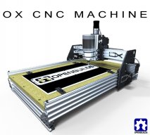
OpenBuilds OX CNC Machine

Discussion in 'CNC Mills/Routers' started by Mark Carew, Dec 15, 2013.

  1. Gareth

    Gareth New
    Builder

    Joined:
    Jan 23, 2014
    Messages:
    15
    Likes Received:
    8
    I'm working on an MDF version of the OX. MDF has great dimensional stability but on a small scale it lacks the hardness of Aluminum, Steel and Garolite. Forces on the parts will cause the holes to deform which results in sloppy linear motion over time. To make up for this in the design, I'm going to pass all of the 'axles' for the V-Wheels through a torsion box structure. This gives them two support points at least 20mm apart. It will act as if the the part was a 1" thick solid block of MDF but it will be made from 1/4" MDF sheets you can get at Home Depot and cut on a 50W laser. The belts will all run outside the aluminum rail so it will be possible to use 9mm x 3mm GT3 belts. The X rails are secured to the vertical torsion box members as well as the outside plate. They are spaced further apart than in the OX design so that the V-Wheels contact centers form a square when viewed from the side. I'm also planning for a taller Z and spaced the Z wheels out further. These two changes combined should give us a very rigid Z-axis.

    Y Gantry Plates MDF.png

    I'm still finishing up the X/Z axis core. I realize that there needs to be some play to align the X rails to be parallel and match the final width of carriage. Making something thats rigid, long lasting, easy to assemble and easy to adjust (you have to reach all of those eccentric spacers!) is a difficult challenge in wood. But its fun to try :thumbsup:
     
    Mark Carew likes this.
  2. Tweakie

    Tweakie OpenBuilds Team
    Moderator

    Joined:
    Jan 18, 2014
    Messages:
    784
    Likes Received:
    326
    Interesting approach Gareth and it certainly looks promising. I look forward to seeing the finished result.

    Tweakie.
     
  3. Gadroc

    Gadroc New
    Builder

    Joined:
    Feb 3, 2014
    Messages:
    8
    Likes Received:
    0
    Mark thanks for posting up this design. I recently built a 2x4' shapeoko and I'm not entirely happy with how it scaled up. I setup mine with a 4' X gantry for easier use in the garage. Unfortunately this X gantry twists easily even after adding an addition 20x40 and bolting them together. I'm going to be converting it over to a OX with a 2' X axis and I'm currently in the CAD phase and have a couple questions.

    I use Mach3 and I've noticed it would be incredibly helpful to have a Z home switch. My CAM software ends up each job moving the Z to machine zero and then to Y zero. It's really easy to forget to manually move Z up to before ref all home making it really easy to run into fixtures. Has anyone figured out a good way to put a limit switch on the Z axis?

    The Z access threaded rod plates have a recess of 16mm for a 5x16x5 bearing and a lock collar is used to keep it in place. Unfortunately the only 8mm lock collars I can find all have a 16mm OD. This will cause the collar to rub against the outer shoulder of the bearing instead of spin freely with the threaded rod. I'm currently planning on using two thin 8mm hex nuts instead of the lock collar. Snug up the bearing with the first and then tighten another nut against it. Doing this on both axis. Anyone see issues with this?

    What type of garolite are people using and where are they sourcing it in the US? McMaster has several different grades and I'm not sure which is most appropriate in this use case. Since I have the shapeoko or access to a 4x8 showboat if necessary, I should be able to go slow and either do 1/4" aluminum or garolite. Should I just go straight to the aluminum?
     
    #333 Gadroc, Feb 10, 2014
    Last edited: Feb 10, 2014
  4. Mark Carew

    Mark Carew OpenBuilds Team
    Staff Member Moderator Builder Resident Builder

    Joined:
    Jun 28, 2013
    Messages:
    2,758
    Likes Received:
    2,441
    @Gareth Nice looking design, looks like its going to be a very strong machine. Looking forward to your build :thumbsup:

    @Gadroc Thank you for the tip on the lock collar tip :)
    Here what I used
    Mcmaster Garolite http://www.mcmaster.com/#85315k134/=qmsx0i

    Just wanted to say Its awesome to see this design being tweaked to perfection! This is what a maker community is all about, keep up the good work guys :)
     
  5. Robert Hummel

    Robert Hummel Custom Builder
    Moderator

    Joined:
    Nov 14, 2013
    Messages:
    978
    Likes Received:
    715
    A friend of mine built a cnc with MDF and had issues with the wood chipping/wearing at the wheel bolts so he cut new parts and sprayed them with a hard laqur finish to harden.
    He said it worked for him, maybe something you might want to try
     
  6. Robert Hummel

    Robert Hummel Custom Builder
    Moderator

    Joined:
    Nov 14, 2013
    Messages:
    978
    Likes Received:
    715
    Rick 2.0 likes this.
  7. Greenman

    Greenman New
    Builder

    Joined:
    Jan 21, 2014
    Messages:
    63
    Likes Received:
    19
    Gareth- Sounds like a great idea. I had an idea a while back of stacking laser cut thin plywood to create a part. If you have a laser you could cut several layers of say baltic birch plywood instead of mdf. If you are worried about the wheel shafts deforming the mdf you could add bronze bearings or even drill bushings. I don't know how long you want it to last long enough to mill out some better ones. I use baltic birch a lot for jigs and fixtures. It is hard and stable and relatively easy to find. You can often find it very thin that is used in making model airplanes. Keep us posted with how you make out. Best Bill
     
    Gareth likes this.
  8. Gadroc

    Gadroc New
    Builder

    Joined:
    Feb 3, 2014
    Messages:
    8
    Likes Received:
    0
    @Robert Hummel Thanks for the link. The sites I was looking at had the same for about $55. Looks like I'll be ordering some aluminum. Any recommendations on bit to pick up for working on this?

    One other question around tolerances. The standard v-slot build plates have clearance between wheel holes of v-slot thickness + 20.64. The OX plates had 1-2 millimeters additional. Was this intentional or just sketch up inaccuracies? I'm in the middle of converting the drawings into another cad system which support arcs / circles and can push back up some DXF without the sketch up off by partial millimeters problems.
     
  9. Gadroc

    Gadroc New
    Builder

    Joined:
    Feb 3, 2014
    Messages:
    8
    Likes Received:
    0
    @JustinTime Sketch up does not (at least last time I used it) handle circles as arcs. Cut a hole in something and it's immediately a set of line segments and when exporting it converts arcs to line segments as well. This can be seen in Mark's DXF files. This leads to several small inaccuracies in the resulting files and potential problems with CAM / machining if you have to many segments per arc.

    I'd highly recommend anyone using sketch up for mechanical parts look at Autodesk Fusion 360. It has parametric features more suited to designing things like this and has a free hobby license level and built in community design features. SketchUp is free as in beer, but not open source so there is not really a philosophical reason to stay with it.

    I was not referring to bit size, but type as for these plates you have to use 1/8th cutter since M5 holes < 6.35mm. Machining 6061 is it best with a straight flute, o-flute, downcut, uncut, etc… Any recommended or avoided coatings.
     
  10. Gareth

    Gareth New
    Builder

    Joined:
    Jan 23, 2014
    Messages:
    15
    Likes Received:
    8
    I used MArk's drawings as reference in my CAD program but I replaced all the holes with real circles...

    Ill have to check out Autodesk Fusion 360.
    My current favorite parametrics CAD tool is Moment of Inspiration: http://moi3d.com/
    Made by the same dude that wrote Rhino. Outputs to OpenNURBS format and STL.
     
  11. Mopar32985

    Mopar32985 Well-Known
    Builder

    Joined:
    Dec 7, 2013
    Messages:
    128
    Likes Received:
    47
    Had some more parts that came in today. Got some more done on the z axis. Just waiting for some extruded aluminum to come in
     

    Attached Files:

    bobt, Robert Hummel and Mark Carew like this.
  12. Dave M

    Dave M New
    Builder

    Joined:
    Dec 30, 2013
    Messages:
    15
    Likes Received:
    5
    Wow. So cool Great job. Can't wait, my parts are shipped.
     
  13. Gadroc

    Gadroc New
    Builder

    Joined:
    Feb 3, 2014
    Messages:
    8
    Likes Received:
    0
    Fair enough, but I'd say the same to you
    SketchUcam is not another CAD system, so the tangent is meaningless. I don't care that SketchUcam can back track SkethUp line-segments back to arcs for generating g-code. The CAD piece is important to me as I'm realigning some things to fit with other components I already have, and I already have more capable CAM software. Quite honestly DXF output from SketchUp is about as useful as STL for anyone trying to modify a design, which is to say crap. Circles/arc don't have dimensions or center points and I've never seen a SketchUp design that was dimensionally accurate. All dimensions are off by fractions of millimeters, which means they are a pain to align in an assembly, as hole patterns don't line up. You end up redrawing them dimensionally accurate and replacing all arcs with fitted arcs and then re-dimensioning them because the are always again fractions of a mm off. In my opinion SketchUp is a great free form design system, but rubbish for detailed mechanical parts or CNC work. To each their own.
     
  14. The Dude

    The Dude Well-Known
    Builder

    Joined:
    Jan 2, 2014
    Messages:
    243
    Likes Received:
    103
    Here's how I did my z limit+home switches http://www.openbuilds.com/builds/optical-limit-home-switches.512/

    Instead of lock collars I used nuts and drilled+tapped a set screw to lock them in place. It allows me to pretension the threaded rod into place and then lock it there.... seems to help. My bearings are 608 so the nut only touches the inner race. I tried just the nut but it spun loose.
     
  15. David the swarfer

    David the swarfer OpenBuilds Team
    Staff Member Moderator Builder Resident Builder

    Joined:
    Aug 6, 2013
    Messages:
    3,462
    Likes Received:
    1,915
    then it is time you upgraded both Sketchup (at least to 8) and SketchuCam (1.1b) because both most definitely DO produce true arcs. You cannot see the arcs in Sketchup because it draws them at straight lines, but the Gcode will contain G03/G02 commands for the arc segments
    IF!
    you have not exploded or edited the arcs in such a way that makes Sketchup think they are lines segments.

    DXF files can be a real export/import problem and I'm never surprised when something goes wacky in them ;)
    in particular arcs getting converted to polygonals.

    example I just drew and created Gcode from in Sketchup8
    this is a 100mm square with the top right corner rounded off.
    Code:
    %
    (Generated by SketchUcam {1.1c-beta})
    (Bit diameter: 3.2mm)
    (Feed rate: 2000.0mm/min)
    (Plunge Feed rate: 1500.0mm/min)
    (Material Thickness: 4.0mm)
    (Material length: 2500.0mm X width: 1300.0mm)
    (Overhead Gantry: true)
    (Retract feed rate NOT limited to plunge feed rate)
    (Optimization is ON)
    (www.PhlatBoyz.com)
    (Davids defaults)
    G90 G21 G49 G61
    M3 S15000
    G0   Z5.000    
       X48.351       Y76.545   
    G1   Z-5.600     F1500
       X151.551    F2000
       Y132.684  
    G17 G3   X151.151      Y138.781      Z-5.600       R47.114   
       X149.949      Y144.826      Z-5.600       R47.114   
       X147.968      Y150.662      Z-5.600       R47.114   
       X145.242      Y156.190      Z-5.600       R47.114   
       X141.818      Y161.315      Z-5.600       R47.114   
       X137.754      Y165.948      Z-5.600       R47.114   
       X133.120      Y170.012      Z-5.600       R47.114   
       X127.996      Y173.436      Z-5.600       R47.114   
       X122.468      Y176.162      Z-5.600       R47.114   
       X116.632      Y178.143      Z-5.600       R47.114   
       X110.587      Y179.345      Z-5.600       R47.114   
       X104.490      Y179.745      Z-5.600       R47.114   
    G1   X48.351   
       Y76.545   
    G0   Z5.000    
    G0 X0 Y0 (home)
    G0   Z35.560   
    M05
    M30
    %
    
     
    Mark Carew likes this.
  16. Gadroc

    Gadroc New
    Builder

    Joined:
    Feb 3, 2014
    Messages:
    8
    Likes Received:
    0
    @JustinTime, It is and I understand why people use it… and people get passionate about their tools! I just do more than SketchUCam can do, which btw is AWESOME value. This means Sketchups anemic export capabilities (3D Surfaces or segmented 2d) becomes a major stumbling block. For wood and foam I would agree… but for something like building an OX I'm a little more careful. A small inaccuracy in a plate could lead to HOURS of frustration trying to square up or track down amplified inaccuracies at the cutting tool.

    Back on topic. My first parts order arrived yesterday, thanks @kram242! I just need to finish up the CAD model to get my cut area where I want it and order the last bits of table support extrusion from misumi and cut the plates (one the aluminum for them arrives.)

    @The Dude have you worked out how/where to mount the limits for the Z axis. It's tight fit to get things where the Z motion would trigger them.
     
  17. Aleksandar

    Builder

    Joined:
    Feb 9, 2014
    Messages:
    37
    Likes Received:
    24
    I am really looking into building OX as I have been looking to build one router for a while now. The plan is to bild with Aluminium, BUT shipping cost from US is a kill.
    Anybody knows if V-Slot is available in Europe?
     
  18. DelMar63

    DelMar63 New
    Builder

    Joined:
    Feb 12, 2014
    Messages:
    19
    Likes Received:
    1
    I am intresting too building OX and I am also from Eurepe . But I would like to know the cost for the OX 2*4 complete kit with the plates. and an estimation for the shipping will be good.....
    Indeed it looks awesome machine.
     
  19. Greenman

    Greenman New
    Builder

    Joined:
    Jan 21, 2014
    Messages:
    63
    Likes Received:
    19
    There's a guy in England that is a distributor he is called Robo-Cutter Uk. Go to the openbuild store and check the news that is where the announcement of distributors it. Good luck in your builds!
     
  20. DelMar63

    DelMar63 New
    Builder

    Joined:
    Feb 12, 2014
    Messages:
    19
    Likes Received:
    1
    Good morning Thanks guys. I will look right away. !!
     
  21. Colin Russon

    Builder

    Joined:
    Dec 4, 2013
    Messages:
    47
    Likes Received:
    24
    Just a short note to write that my VPS server is down, the host company (GoDaddy) are onto it but I did not want anybody to think that the website was down for any other reason then the hosting company seems to be having problems with the server. The correct link is www.robocutters.co.uk (when its working again), thanks.

    Colin.
     
    #351 Colin Russon, Feb 13, 2014
    Last edited: Feb 13, 2014
  22. Rick 2.0

    Rick 2.0 OpenBuilds Team
    Staff Member Moderator Builder Resident Builder

    Joined:
    Dec 20, 2013
    Messages:
    2,893
    Likes Received:
    1,552
    The website appears to be working fine. For some reason however the link you provided doesn't click through with the ".uk" at the end so it goes nowhere. Adding the .uk at the end in the address bar allows it to connect. www.robocutters.co.uk
     
  23. Colin Russon

    Builder

    Joined:
    Dec 4, 2013
    Messages:
    47
    Likes Received:
    24
    Thanks for the info and yes, all working again now (phew!) and URL edited to go to the website as well...
     
  24. DelMar63

    DelMar63 New
    Builder

    Joined:
    Feb 12, 2014
    Messages:
    19
    Likes Received:
    1
    Hey guys. Did anyone try ever to move the whole X axis up and down as Z axis , using two steppers but making the connection of the router more strong because it will stand only at X axis wheels ? Of course this increase the cost of the construction , but do we gain something of it ? More stability let say as more clearance of the height ?. I am asking you because I am going to order materials to construct my own machine and just I had that thought.
     
  25. Tweakie

    Tweakie OpenBuilds Team
    Moderator

    Joined:
    Jan 18, 2014
    Messages:
    784
    Likes Received:
    326
    Very interesting idea.
    I use Mach3 as my machine control software and this will only allow for 2 axes to be slaved (such as Y and A for the 2 motors driving the Y axis back and forth). Other machine control software may be different.

    Check out this build http://openbuilds.com/builds/spunks-cam.522/

    Tweakie.
     
    #355 Tweakie, Feb 13, 2014
    Last edited: Feb 13, 2014
    DelMar63 likes this.
  26. Colin Russon

    Builder

    Joined:
    Dec 4, 2013
    Messages:
    47
    Likes Received:
    24
    Do you mean like this?
    http://www.openbuilds.com/builds/spunks-cam.522/
     
  27. Tweakie

    Tweakie OpenBuilds Team
    Moderator

    Joined:
    Jan 18, 2014
    Messages:
    784
    Likes Received:
    326
    My apologies Colin - I must have been editing my post to add the link at the same time you were making your post. :oops:

    Tweakie.
     
  28. Colin Russon

    Builder

    Joined:
    Dec 4, 2013
    Messages:
    47
    Likes Received:
    24
    no need to apologize we were both on the same track :)
     
  29. Mopar32985

    Mopar32985 Well-Known
    Builder

    Joined:
    Dec 7, 2013
    Messages:
    128
    Likes Received:
    47
    Well since it was a snow day today (around 18" and counting). I got some more dont on my OX. This thing is really starting to impress me very fun build.
     

    Attached Files:

    Mark Carew likes this.
  30. Mopar32985

    Mopar32985 Well-Known
    Builder

    Joined:
    Dec 7, 2013
    Messages:
    128
    Likes Received:
    47
    @JustinTime , trust me i cant wait. This V-slot is amazing its like an erector set for machines. The more i use it the more im impressed with it
     

Share This Page

  1. This site uses cookies to help personalise content, tailor your experience and to keep you logged in if you register.
    By continuing to use this site, you are consenting to our use of cookies.
    Dismiss Notice