Welcome to Our Community

Some features disabled for guests. Register Today.

Triple C-Bot

Discussion in '3D printers' started by adamcooks, Feb 11, 2015.

  1. Zappo

    Zappo New
    Builder

    Joined:
    Nov 30, 2014
    Messages:
    16
    Likes Received:
    0
    Glad you're back on the thread. Keep the improvements coming! Triple C is my fall back.

    Heard that the Sailfish code is highly tuned compared to Marlin.....but Marlin should still be viable assuming some ifdefs?

    Having the belts hidden in the rails is pretty clean. I'm more interested in creating a heated chamber, than an outside shell on the printer, so the steppers would be mounted outside in cool air. Also planning to do the twist-belt-cross-over so the return belt from the stepper would still be inside the 20x20 Y rail.

    I'm starting printing tweaks on a 3 wheeled xy_barEnd with inline belts for a 20x20. The tension wheel on the bottom looks like http://www.thingiverse.com/thing:110283. With stacked belts, 4 wheels would be the only way to go.

    Dan Newman's designs use linear bearings and round rails. An advantage of this is he doesn't have the X rail separating the belts as they connect the X-carriage, creating a torque moment. The belt forces are pretty much inline driving the X-carriage. I'm trying something similar, by putting both pulleys on one side of the X rail.

    xy_end.jpg
     
  2. adamcooks

    adamcooks Well-Known
    Builder

    Joined:
    Nov 6, 2014
    Messages:
    244
    Likes Received:
    65
    Interesting layout, I can't wait to see it whole.

    Dan and el have all said that at this size unsupported round rod could be problematic.
     
  3. Joseph Ecker

    Builder

    Joined:
    Apr 5, 2015
    Messages:
    30
    Likes Received:
    3
    Hi Adam,

    A friend and I are building off your design and I came across something odd (after printing them, doh!) with the X and Y Idlers. Is there a reason the dimensions for the v-slot spacing is different between the front/back and side openings?

    I'm doing a mock-up in Blender before making the big "cut extrusion" commitment and noticed that one of the openings is larger than the other. I also verified with some calipers that they are about 0.4mm off (one opening on a printed part measures 40.15mm and the other opening is 39.75)

    Also, for the Z-end 1 and 2, there are two of each, right? Trying to reference your pictures and it looked like you had one of them printed in red...

    Thanks much,

    -Joe
     

    Attached Files:

  4. adamcooks

    adamcooks Well-Known
    Builder

    Joined:
    Nov 6, 2014
    Messages:
    244
    Likes Received:
    65
    Let me check the idlers. This was the exercise in self taught CAD.

    there is a top and bottom to the Z ends. one of the has a flat on it for tripping the Z endstop. Each side uses one #1 and one #2
     
  5. adamcooks

    adamcooks Well-Known
    Builder

    Joined:
    Nov 6, 2014
    Messages:
    244
    Likes Received:
    65
    The part printed in red was the modified car that used with my z endstop. The original C-bot used different style switch, and mounted to the rear Z slider. When I found the mini endstop switches I used that to mount directly to the vrail and trip on the car.

    I attached the idlers from Carl's thread, idlers and motor mounts are the 4 common parts
     

    Attached Files:

  6. adamcooks

    adamcooks Well-Known
    Builder

    Joined:
    Nov 6, 2014
    Messages:
    244
    Likes Received:
    65
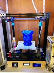
    Have been using the Triple-C a bit more these days, the little gremlins to chase are getting fewer and fewer. My neighbor came over with a broken screen door handle, and said " what can you do about this?" 45 minutes later...
    [​IMG]

    A single wall vase, eSun PETG printed at 245c/70. 85mm/sec
    [​IMG][​IMG]
    [​IMG]
     
  7. Mark Carew

    Mark Carew OpenBuilds Team
    Staff Member Moderator Builder Resident Builder

    Joined:
    Jun 28, 2013
    Messages:
    2,758
    Likes Received:
    2,441
    Looks like you really have it dialed in now @adamcooks Its a great feeling when a printer gets to this point. Really nice work on this build congrats :thumbsup:
     
  8. Joseph Ecker

    Builder

    Joined:
    Apr 5, 2015
    Messages:
    30
    Likes Received:
    3
    I've got a couple outstanding questions while I wait for more parts to arrive:
    1) What did you do with your thermocouple wires? Did you use normal copper cable (twisted?) to extend them down to your mightyboard? I saw some lengthy discussion on a google groups forum about using "type-k" wire for the thermocouples...
    2) Where can I find the 2 and 4 position connectors for the mightyboard? (i.e. power, ex1/ex2, hbp, thermocouples, and cs-fan) I found this one on digikey, but not sure if it's the right one:
    http://www.digikey.com/product-detail/en/20020038-H021B01LF/609-4585-ND/2683192

    Thanks in advance for any info/help...
     
  9. Elmo Clarity

    Elmo Clarity Journeyman
    Builder

    Joined:
    Jan 17, 2015
    Messages:
    505
    Likes Received:
    149
    Any standard hookup wire should work for the thermistor. Type-K is not a wire type, but a type of thermal couple. Those are not used much since the thermistor tends to be more accurate and it takes special circuitry to use a thermocouple.


  10. Joseph Ecker

    Builder

    Joined:
    Apr 5, 2015
    Messages:
    30
    Likes Received:
    3
    Thanks for the reply, Elmo...

    However, the controller I'm using, a mightyboard, uses thermocouples for the hot-ends. I have two thermocouples, but the wires are a few feet shorter than what I need (unless I end up mounting the mightyboard up above the printer)...
     
  11. Elmo Clarity

    Elmo Clarity Journeyman
    Builder

    Joined:
    Jan 17, 2015
    Messages:
    505
    Likes Received:
    149
    Any hookup wire will still work. Try using the same guage wire as what is currently on them.
     
  12. adamcooks

    adamcooks Well-Known
    Builder

    Joined:
    Nov 6, 2014
    Messages:
    244
    Likes Received:
    65
    That is not true of thermocouple. The two wires are of a different material and must be extended using special terminal blocks and type k wire. I found extra long tc's on eBay and didn't have to extend them. I was going to mount the motherboard on the back as opposed to extending them.

    Thermocouple are far more accurate and can withstand higher temps

    Those are the correct plugs from digikey. I purchased cables from uncle Chuck and extended them instead of crimping. I believe the stepper cable connectors are listed on my BOM.
     
  13. adamcooks

    adamcooks Well-Known
    Builder

    Joined:
    Nov 6, 2014
    Messages:
    244
    Likes Received:
    65
    Thought I would update the thread here. Turns out that my X axis is mirrored. I was printing a box for a heating system for my replicator with a hole offset to one side of the case, well it printed on the wrong side. My build area is rotated 90degrees clockwise, as looking at the printer X axis is front to back Y axis is side to side, and I will try again to get it more "clone like". The traditional replicator homes, XY max, in the back right corner, X would be width and Y would be depth.

    So in thinking about this post, I just realized that my printer is homing Y min, X max. My build area is rotated, but my homing locations are correct. I do remember the fun of setting up the steppers and endstops initially. With standard cartesian setup you are chasing a single stepper, coreXY really could be either motor, or just inverting an axis in repG. This will be a fun gremlin to chase.
     
  14. adamcooks

    adamcooks Well-Known
    Builder

    Joined:
    Nov 6, 2014
    Messages:
    244
    Likes Received:
    65
    Took a few hours but I did mange to get my printer orientated correctly, all endstops are in the correct location, and it is now laid out exactly like my replicator. As long as it will fit on the build plate, I can print the same file on 2/3 of my printers, and I am working on my third. My side project is running sailfish on my prusa i3 via an Azteeg x3. The main benifit of sailfish is offloading the conversion of gcode into stepper pulses freeing up much needed space in our mr coffee 8 bit chips. I feed my Triple C .x3g files which is unreadable to human and simply machine code telling it what to do. I got a few large parts off for the cabin heater on my replicator and decided that it was printing way too nicely to leave alone, so I installed a volcano heaterblock and 1.2 mm nozzle. Fun times. It was like looking down the barrel of a shotgun. I used my .3mm feeler gauge to level my nozzle. The Z endstop on the TripleC was ridiculous easy to set. With it loose, and resting on the Zstage I just ran the belt until the bed hit the nozzle, then tightened. 1/4 turn of my bed screws and I was printing.
    Heres a good pic of it installed, I only lost 9mm of z height
    [​IMG]
    [​IMG]
    Just a little over extruded, but otherwise pretty good, 20x20x10 cube.
    [​IMG]
    The cube was like jello when it was done, took a few minutes for it to cool and solidify.
    Quick video of it printing bridge test part

    1 minute of printing at 75mms, this is pushing a ton of plastic. Notice how fast the extruder drive gear is turning.


    I now need a cooling fan I think. I have no more room at the front of my frame to fit a fan, I think I will have to attach it to the back side of the XY gantry. A big big blower I think.
     
  15. adamcooks

    adamcooks Well-Known
    Builder

    Joined:
    Nov 6, 2014
    Messages:
    244
    Likes Received:
    65
    2hours 58 minutes, 71.2mm tall, 79.8 meters of filament
    [​IMG]
     
  16. Joseph Ecker

    Builder

    Joined:
    Apr 5, 2015
    Messages:
    30
    Likes Received:
    3
    The pictures don't seem to be showing for me, but the vids are definitely impressive!

    I'm very interested in hearing about you getting Sailfish running on your Azteeg X3. From what I can tell, the Azteeg board looks to be a bit more robust than a Mightyboard. Are you able to use ReplicatorG and/or Makerware with it?

    I've downloaded the source ball from github a while back, and also installed the toolchain(s) in order to compile it. Any other gotchas with loading Sailfish on the X3?

    My build is progressing... I just ordered my closed-loop GT2 belt this week and I temporarily hooked up all the steppers to a RAMPS board I have (in order to test steppers, wheel fittings and such) and got it moving :)

    I also modeled/printed two brackets for the X and Y endstops. At this point, I'm trying to determine which is going to be my X and Y axis and whether or not my endstops are going to be MIN or MAX. Looking at your videos, I think my X will run parallel to your moving Z-bar, and my MIN will be in the far right corner.

    Thanks for keeping us updated on the tuning/tweaking of your build!
     
  17. adamcooks

    adamcooks Well-Known
    Builder

    Joined:
    Nov 6, 2014
    Messages:
    244
    Likes Received:
    65
    The installation of the X3 went through RepG, point to sailfish beta site, it was quite painless. Start Gcode is a different story. Im not sure whats going on with the photos, new problem for me. I am excited to get this big nozzle tuned and printing well.
     
  18. adamcooks

    adamcooks Well-Known
    Builder

    Joined:
    Nov 6, 2014
    Messages:
    244
    Likes Received:
    65
    Hese some pics of my first Benchy
    IMG_20150904_110851.jpg IMG_20150904_110859.jpg IMG_20150904_110908.jpg IMG_20150904_110939.jpg
    1.2mm nozzle, at 75mm/sec. I need cooling. Printing the smokestack, looked like peanutbutter being smeared into shape.
     
  19. CapnBry

    CapnBry Well-Known
    Builder

    Joined:
    Jun 13, 2015
    Messages:
    100
    Likes Received:
    54
    Hey Adam, how did you go about fixing your mirrored prints? Just move the endstop to the other side and flip the wires to the stepper? I've got about a kilo of prints here that I've realized are mirrored. I was going to blame Simplify3D's FLIP setting, but no matter which direction I flip it, the print comes out the same so it appears that setting is only for visualization in the gui.

    EDIT: Wait, fixed my X mirroring by inverting both motor plugs and also swapping them. then telling the firmware to home to max on the X direction.
     
    #79 CapnBry, Sep 5, 2015
    Last edited: Sep 5, 2015
  20. adamcooks

    adamcooks Well-Known
    Builder

    Joined:
    Nov 6, 2014
    Messages:
    244
    Likes Received:
    65
    I thought I had fixed them. My parts are coming out correctly, end stops all functioning properly, orientation in the"proper"fashion, slicer preview matching what is on my screen...... But then I find out that I'm jogging backwards.
     
  21. CapnBry

    CapnBry Well-Known
    Builder

    Joined:
    Jun 13, 2015
    Messages:
    100
    Likes Received:
    54
    It's always something! In Octoprint I can flip the jog controls to match the printer, because mine is the same way depending on how you look at it. Looking from the front, the origin is the back right corner so which direction does the "Up Arrow" move the axis? It is a mystery!

    After spending all that fun time building the bowden force sensor I am not super happy with the bowden concept (9mm of retraction just to get rid of 90% of the blobbies!). Did you make your own mount for your extruder? I see that the XY carriage has a block to mount it to, but I'm wondering if there's a plastic part on the extruder that mates with that or if the mount is part of the extruder assembly you have.
     
  22. adamcooks

    adamcooks Well-Known
    Builder

    Joined:
    Nov 6, 2014
    Messages:
    244
    Likes Received:
    65
    Yes, I'm beginning to see that octoprint is the future. I have a flashed image but haven't powered it on, there's been a solar flare in the wedding season this year preventing me from having any leisure time.

    Currently I'm on v2 of my extruder mount. It's just an extruded aluminum L shape to fit into the pocket on the plastic. My first version didn't have that pocket and it jiggled. I just received a new bracket to mount the extruder on. I will have to do a v3 of my gantry with a bigger pocket. This bracket is the steel one found on the duplicator i3, it shares extruder design with my bot. This will allow me to use the cooling fans for the i3 as well. http://www.thingiverse.com/thing:1004798 should do nicely. Just need to accommodate the volcano block spacing. I may even ditch the volcano block and use the standard e3d .8 nozzle. Jetguy's ulti-replicator 2 ( 4' cube build) uses a homemade 1.2mm nozzle on the standard heater block, although I think it was brass. Switch to direct drive you will never look back.
     
  23. CapnBry

    CapnBry Well-Known
    Builder

    Joined:
    Jun 13, 2015
    Messages:
    100
    Likes Received:
    54
    I do love non-bowden. My i3 was a J-head with a wade's extruder, which probably cost a total of about $30 and it produces some really really great prints. It's just the machine around it is pretty unreliable that prompted this whole upgrade. Now I've got a $200 hotend that needs a fan running on it all the time and the quality has gone down. I'm not a big fan of having to sling around a motor on the XY carriage but my i3 does it just fine so I don't know why I was so hesitant to just do the same thing. The torque doesn't seem to be an issue though so it should be fine without the wade's gearing and just using a direct filament gripper like you are.

    I definitely need a part cooling fan though too because that makes so much difference in print quality. That one you linked is a monster, I love it!
     
  24. Austin Seagers

    Austin Seagers Well-Known
    Builder

    Joined:
    Oct 13, 2015
    Messages:
    88
    Likes Received:
    48
    Hi Adam,

    Firstly, thanks for sharing your build!

    I'm designing my own printer with a heavy influence from yours. Just wanted to ask for a few close-ups of your Z leadscrew where it meets the lower mount and bearing. Are you using leadscrews with turned down ends that just slot into the inner bearing race? If so, aren't these bearings not rated for axial loads?

    Thanks,
    Austin

    EDIT: Just seen the picture and description of this on the first page of the discussions. These bearings aren't rated fro axial laods though. Have you put a heavy weight on the print bed and noticed any increased friction at all?
     
    #84 Austin Seagers, Nov 3, 2015
    Last edited: Nov 4, 2015
  25. adamcooks

    adamcooks Well-Known
    Builder

    Joined:
    Nov 6, 2014
    Messages:
    244
    Likes Received:
    65

    Sorry it has taken me so long to respond to your requests, after a build hiatus due to cross country move, I had tuning hiatus due to renting a house with bad juju and deciding to buy another house here in Cali. So, I find myself just unpacking "printlandia", as my wifecountant calls it. 2/3 printers set up and my clone printing a caliblock . Hopefully I can get up to speed over in the C-bot thread, I had a google now card pop up about a big switch to direct drive.

    Some pics of my leadscrew mounts. My 8mm leadscrews are turned down to 5mm shaft 20mm on each end. You are correct that the bearings are not rated for axial loads, my test placed 5Kg of filament on the bed and had no difficulty homing ( other then timing out ). I will pose the question over in the google group and see what folks much smarter then I have to say.
    IMG_20151110_010159.jpg IMG_20151110_010206.jpg IMG_20151110_010215.jpg IMG_20151110_010221.jpg IMG_20151110_010239.jpg
     
    Austin Seagers likes this.
  26. Austin Seagers

    Austin Seagers Well-Known
    Builder

    Joined:
    Oct 13, 2015
    Messages:
    88
    Likes Received:
    48
    No worries! At least you're back up and running...

    Thanks for the pictures. If you could link to the google group/thread you mentioned I'd appreciate it.
    And regarding the bearings. It sounds like you had it wrapped up already. 5Kg sounds plenty capable. I suppose the only issue I could foresee is a slow wear and widening of the bearing grooves in between the races resulting in play in the Z axis.

    Nothing to be worried about though i'd imagine.

    Thanks again.
    Austin
     
  27. Elmo Clarity

    Elmo Clarity Journeyman
    Builder

    Joined:
    Jan 17, 2015
    Messages:
    505
    Likes Received:
    149
    So where in Cali did you end up?
     
  28. Carl Feniak

    Carl Feniak Journeyman
    Builder

    Joined:
    Mar 18, 2014
    Messages:
    654
    Likes Received:
    246
    Typically a ball type bearing and handle ~25% axial load relative to it's radial capacity.
     
  29. adamcooks

    adamcooks Well-Known
    Builder

    Joined:
    Nov 6, 2014
    Messages:
    244
    Likes Received:
    65
    I'm in the 707, few blocks from the Vallejo ferry
     
  30. adamcooks

    adamcooks Well-Known
    Builder

    Joined:
    Nov 6, 2014
    Messages:
    244
    Likes Received:
    65
    My kitchen brain said "order the biggest bearing you can find with a 5mm ID"
     

Share This Page

  1. This site uses cookies to help personalise content, tailor your experience and to keep you logged in if you register.
    By continuing to use this site, you are consenting to our use of cookies.
    Dismiss Notice