Welcome to Our Community

Some features disabled for guests. Register Today.

V Rail 3D printer

Discussion in '3D printers' started by Josh B, Sep 8, 2015.

  1. Josh B

    Josh B Well-Known
    Builder

    Joined:
    Nov 4, 2014
    Messages:
    116
    Likes Received:
    42
    Awesome! That would be a dream job for me.
     
  2. Josh B

    Josh B Well-Known
    Builder

    Joined:
    Nov 4, 2014
    Messages:
    116
    Likes Received:
    42
    Thanks Stargeezer, do you always drink beer? LMAO, love your pic.
    Yes, the costs are adding up fast. I'm starting to think "cheap" as I complete the drawings. Down to the Y axis and I can't decide on the linear motion assembly. I have one rendition using 12mms linear rods and bearings. Now I'm drawing one with vrail and wheels. The problem with the wheels is that any adjustments will be a "PITA" once the build plate is installed. The 12mm linear rods s and bearings would be the cheapest option but will require more maintenance over the life of the printer.
    BTW, I've started to sell some of the rc airplane kits, I've had stashed away, to pay for this build. Dang hobbies, need more time and money!
     
  3. stargeezer

    stargeezer Journeyman
    Builder

    Joined:
    Feb 20, 2015
    Messages:
    328
    Likes Received:
    117
    It's a bit involved Josh. The full graphic reads "I don't always downshift when I see a Prius....Unless I'm in my truck". You see, I drive a very, very large, diesel powered truck. It's 4 doors of stretched, Cummins powered funmobile that's got 11" of lift under the suspension, dual rear wheels, and is complete with it's own private elevator. Not everybody understands why I enjoy seeing eye to eye with a Semi Truck drivers and there is a particular segment of the populace who is convinced that because it would take melting down 10 prius to make another truck like mine, that they have a right in insult me and make finger gestures in my direction. Like most properly tuned diesel motors, mine will also burp a bit of black smoke when downshifting or when I engage the Jake brake. I and my fellow big truck fans give this sign to each other to show fellowship and I'm kind hearted enough to want to share that with the unfortunates that are forced to drive a shoebox all day.
     
  4. stargeezer

    stargeezer Journeyman
    Builder

    Joined:
    Feb 20, 2015
    Messages:
    328
    Likes Received:
    117
    And my wife thinks I've got too much time on my hands.
     
  5. Josh B

    Josh B Well-Known
    Builder

    Joined:
    Nov 4, 2014
    Messages:
    116
    Likes Received:
    42
    Dodge huh, nobodies perfect! I'm a Ford guy myself. But, since I'm blessed, I don't even drive my own truck anymore. My employer supplies me with a 2011 3/4T Chevy Duramax to drive during the week, it runs great and doesn't cost me a dime.

    Any suggestions on the type of linear motion mechanism for the Y axis?
     
  6. stargeezer

    stargeezer Journeyman
    Builder

    Joined:
    Feb 20, 2015
    Messages:
    328
    Likes Received:
    117
    I think you've got a great idea with your z axis. Why not echo that in the y axis?

    A ford guy who drives a Chevy? Talk about slumming it! :) Four wheels and a diesel motor at least. My son pulled in the drive this weekend in a new VW Jetta - SHUTTER - but at least it drinks the right fuel. :)
     
  7. Josh B

    Josh B Well-Known
    Builder

    Joined:
    Nov 4, 2014
    Messages:
    116
    Likes Received:
    42
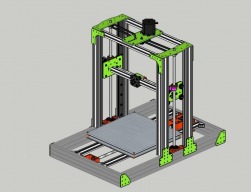
    Here is the (final?) sketch of the VRail screw driven 3D printer.
    I decided to change the plates (shown in green) to G10/FR4 as it is easier for me to cut with my OX cnc. The only plate that will be purchased is the X axis plate for the mini v-wheel assembly (that may change yet too).
    The final drive for the Z axis 10 x 2 5 start screws will be a Nema 23 and a continuous 6 mm GT3 belt. The X/Y axes will be driven by Nema 17's turning 10 x 35 28 start screws from Helix Linear. All lead screw ends will be turned down to 8 mm to fit the bearings and collars that I already have. The Y axis timing pulleys are 28 tooth from Misumi.
    Components shown in orange are printed out of ABS or PLA, un-decide on the type as of now.
    The Y axis will roll on mini V wheels and custom plates, any thoughts on the plate design as drawn specifically the two wheels
    Thoughts?
     

    Attached Files:

  8. Selvakumaran

    Builder

    Joined:
    Mar 22, 2015
    Messages:
    15
    Likes Received:
    0
    Dear Keith,

    I was in the confusion of selecting the correct leadscrew for the Z-axis. When I read this I got some idea. In order to achieve 0.1mmm layer height, using Tr8*8-4 will lead to 2.5 steps and will introduce error. But, you suggested to use 'A Tr8*8-2, with only 2 starts instead of 4, would land on full 0.1 layers, or a Tr8*8-4 using a 1/32 stepper would too'.

    But again in your another reply, you quoted 'Optimum Layer height for Z-axis' from Prusa calculator and told that whether we use microstepping or not, Z-axis movement will jump to the next full step only. This is leading to the confusion. As per your first reply, using Tr8*8-4 using 1/32 stepper will give 0.1 mm layer height without any error.

    But, as per Prusa calculator for Optimum layer height, Tr8*8-4 will not give correct results for 0.1 mm layer height.

    I checked that calculator and found that in order to achieve zero error for 0.1 mm, either we can use Tr8*8-2 with 2 starts (using 1.8 deg stepper) or Tr8*8-4 with 4 starts using 0.9deg stepper.

    Which one would be the good solution? I haven't not seen much people using 0.9 stepper motor . Also, if I am correct, Ultimaker is using Tr8*8-4 with 4 starts and using 1.8 deg stepper only.

    This question is just want to be more clear on the things and not to blame anybody. Correct me if I am wrong anywhere.

    Thanks in advance.
     
  9. Keith Davis

    Keith Davis Veteran
    Builder

    Joined:
    Dec 11, 2013
    Messages:
    507
    Likes Received:
    398
    Selvakumaran

    Sorry for the confusion.

    A Tr8*8-4 and a Tr8*8-2 both travel 8mm per revolution. The first 8 is the diameter, the second 8 is the travel per revolution (lead) and the 4 or 2 is the pitch. Divide lead by pitch to get starts. The Tr8*8-4 has a 2 starts, the Tr8*8-2 4 starts. A Tr8*4-2 would travel 4mm.

    Using Prusa's calculator, any Tr8*8-? (8mm/revolution) at 400 steps per revolution (0.9deg motor) will move 0.02mm per step. That would be excellent for full micron (0.1mm) layers. If you want to run 0.05mm (or any other fraction of a micron) you'd be down to microstepping.

    But, keep in mind, just using a 0.9 degree motor will not give you the 400 steps unless you also use the DRV8825 stepper driver on a control board capable of 400 steps. Example, RAMPS 1.4 can not do 400 steps, it lacks the 4th set of jumper pins and is limited to 200 steps. With RAMPS you can hook up a .9 degree motor and use DRV8825 and they run quieter and cooler because the DRV is a better driver, but they are skipping every other step in the motor and deliver only 200 steps per revolution.

    As you can see, I am no fan of using trapezoidal screws for Z axis. They look pretty, but the math does not work out unless you are moving by microsteps. Microstepping errors are trivial if you have only one Z axis screw motor. But if you have two, a purposefully unlevel bed is part of your design. An 8mm threaded rod with a 200 step motor gives 0.05mm accuracy at full steps. It is a myth that threaded rods are not as accurate as trapezoidal screws. Whether a threaded rod is cut using a die or lathe feed method, the depth may vary due to tool wear, but the lead (threads per meter) will always remain constant. And with a Z axis, that lead is all we are really concerned with. Actually a 6mm threaded rod is perfect - it has 1mm per revolution. Plug 1 mm/revolution into Prusa'a calculator for 1.8 degrees and see that that produces 0.005mm step length. But there are no pulleys or couplers for 6mm, which is why Prusa used a plastic tube to couple the motor and rod on the Prusa i3, since he used a 6mm threaded rod on the i3 to achieve the 1mm lead. An 8mm rod with 4:5 reduction achieves the same 1mm travel, which is what I use.

    JustinTime

    No. A "next full step" is the next "full step". A full step is a physical on-off position in a stepper motor. Any fraction microstep (1/8, 1/16, 1/32) is a theoretical step controlled by current fluctuation from the driver and are inherently not accurate. Mark Carew linked a great article on it.
     
  10. Selvakumaran

    Builder

    Joined:
    Mar 22, 2015
    Messages:
    15
    Likes Received:
    0
    Thanks for the wonderful explanation. Now the things are clear. Still, if you check with other forums, mostly they are considering the ACME lead screws are superior than the normal threaded rods.

    I got a link for M6 rod with antibacklash nut.
    MINIATURE 320 MM CNC STAINLESS STEEL M6 LEAD SCREW & DELRIN NUT - 2 sets
    I am not sure whether this is ordinary threaded rod or Lead screw. They are claiming as Lead screw.

    Also, 5x6mm coupler also available:
    3pcs 5x6mm Aluminium coupler Stepper Motor Flexible Coupling 5mm to 6mm 5*6 mm Shaft Coupler Diameter 19mm Length 25mm-in Shaft Couplings from Industry & Business on Aliexpress.com | Alibaba Group

    If, I use this M6 rod with 5x6mm coupler, with 1.8deg motor, I hope I can achieve full (0.1mm) as well as half (0.05mm) microns also.

    What is your suggestion on this?
     
  11. Keith Davis

    Keith Davis Veteran
    Builder

    Joined:
    Dec 11, 2013
    Messages:
    507
    Likes Received:
    398
    My suggestion? Buy it! I just did...

    That looks perfect. It states it has a 1mm pitch, so I am guessing it is a lead screw with only 1 start, same as a threaded rod. It certainly looks like a lead screw cut with flat face on the thread. And yup, that can give 0.005mm per step with a 1.8deg motor, or 0.05mm per 10 steps. Instead of a coupling, I need a pulley and no one makes a 6mm pulley. But I think I'll try using a 6.34mm (1/4") and shim the 6mm screw with tape the way you'd do a threaded rod into a coupling. BTW, OpenBuilds has a 5mm/6mm coupling more expensive than the Alibaba but available this year.

    If it wasn't for their high shipping I'd be tempted to try their Linear Guide Rail & Slide Bearing Block too. But....

    Thanks for the link Selvakumaran!
     
  12. Selvakumaran

    Builder

    Joined:
    Mar 22, 2015
    Messages:
    15
    Likes Received:
    0
    Thanks for the suggestions.. I am planning to use this lead screw for Z-axis and also planning for Auto bed levelling sensor. Due to the Auto level sensor only, I am going with Lead screw with Anti-backlash nut.

    As you said, you have already bought this Lead screw, in which build are you using? Also, how about the shipping and delivery time? Also quality?

    May I know why you are requiring a pulley? Planning to use it in X or Y axis?
     
    #42 Selvakumaran, Dec 11, 2015
    Last edited: Dec 11, 2015
  13. Rick 2.0

    Rick 2.0 OpenBuilds Team
    Staff Member Moderator Builder Resident Builder

    Joined:
    Dec 20, 2013
    Messages:
    2,892
    Likes Received:
    1,551
    @Selvakumaran, thanks for pointing out that ebay seller. They have another item I hadn't seen before, the Q-module Linear Guide & Lead-screw system, a V-slot based guide rail & lead screw system with built-in anti-backlash. Once I get a mill up and running, these should be fairly simple to DIY.
     
    Keith Davis likes this.
  14. Keith Davis

    Keith Davis Veteran
    Builder

    Joined:
    Dec 11, 2013
    Messages:
    507
    Likes Received:
    398
    @Selvakumaran, I bought it after you gave me the link, so I can't tell you more than you know. Wish I hadn't though. Like @Rick 2.0, I've looked at their inventory and see other possibilities. Perhaps I'll find a use for

    Just a quick slap together of how I might use their compact guide system for X and 6mm block system for Z axis....
    [​IMG] [​IMG]

    As you can see, I'm a atheist when it comes to conventional design.

    As per your plan to use an Auto bed levelling sensor. Why? With a full step on your two Z axis motors your bed will never get unlevel once you've leveled the corners. Auto bed leveling is a system that compensates for the fact that two Z axis motors rising on microsteps can not possibly remain in sync with each other. By using a full step design you'll eliminate the problem.
     
  15. Selvakumaran

    Builder

    Joined:
    Mar 22, 2015
    Messages:
    15
    Likes Received:
    0
    @Rick 2.0, Yes, they have a good collection of Linear guides based on V-slot profiles.

    @Keith Davis, Sorry. Forget to mention clearly. As this discussion is for 'V Rail 3d printer', I didn't give much info.

    Actually I am building a 3d printer with Crane style (like Bukito & IndieLC). I am planning to use C-beam structure for Z and Y-axis to give more rigidity.
    It will have only one Z-axis motor. Hence, I am planning to go for Auto bed levelling. Once I start the original build, I will share the photos.
     
  16. Keith Davis

    Keith Davis Veteran
    Builder

    Joined:
    Dec 11, 2013
    Messages:
    507
    Likes Received:
    398
    @Selvakumaran I worked on a Crane design with a C-Beam for Z axis last spring. The only problem I had (which made me shelve it) was the joint keeping the C-Beam rigidly perpendicular to the frame piece the Y is attached to. But I think I solved that last week, so I'm back to working on it again. Look forward to seeing your build.
     
  17. Lozza50

    Lozza50 New
    Builder

    Joined:
    May 20, 2014
    Messages:
    6
    Likes Received:
    1
     
  18. Lozza50

    Lozza50 New
    Builder

    Joined:
    May 20, 2014
    Messages:
    6
    Likes Received:
    1
    I assume it's a Nema23 140oz is the size
     
  19. Awestruck

    Awestruck New
    Builder

    Joined:
    Dec 17, 2017
    Messages:
    76
    Likes Received:
    13
    Hi @Selvakumaran, @Keith Davis -

    I'm reading trough this thread, looking at my making my own 3D printer, and wonder how the test with the M6 lead screws went or if you tested the guide system.
     

Share This Page

  1. This site uses cookies to help personalise content, tailor your experience and to keep you logged in if you register.
    By continuing to use this site, you are consenting to our use of cookies.
    Dismiss Notice