Welcome to Our Community

Some features disabled for guests. Register Today.

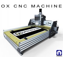
OpenBuilds OX CNC Machine

Discussion in 'CNC Mills/Routers' started by Mark Carew, Dec 15, 2013.

  1. Rick 2.0

    Rick 2.0 OpenBuilds Team
    Staff Member Moderator Builder Resident Builder

    Joined:
    Dec 20, 2013
    Messages:
    2,892
    Likes Received:
    1,551
    This one should satisfy your inner cheap at $426.87
    This one may be even less.
     
  2. R_B

    R_B New
    Builder

    Joined:
    Jul 18, 2015
    Messages:
    70
    Likes Received:
    12
    I am getting the idea that MeshCAM is good for "carving" use, e.g. a small ball end mill that will go in almost anywhere and get all the material out - eventually.
    Perhaps one or two tool changes, e.g. if a straight end mill is needed for some inside corners.

    OTOH Fusion 360, HSMWorks etc are oriented toward "machine shops" running more traditional machine tools that may have some very large number of "drills and mills" - likely in an automated tool changer.
    Each hole/pocket/profile/tapped hole/whatever has its process & tool selection optimized.

    Is this even close ?
     
    #2942 R_B, Oct 8, 2015
    Last edited: Oct 8, 2015
  3. Jonny Norris

    Jonny Norris Well-Known
    Builder

    Joined:
    Aug 17, 2014
    Messages:
    491
    Likes Received:
    95
    In regards to Hsm I know what your saying, Hsm does have vast functionality giving you that impression. But it can be used for cnc routing as effectively as any other cam as the operations remain the same.

    It is more oriented to 3D strategies, but it's horses for courses. I use vectric for 2d stuff as its faster to program, and I use Hsm for 3D strategies as i find it faster to program and you get a better simulation and crash detection.

    The tooling setup in Hsm can be daunting at first but you can ignore most of it and just setup the tool the same as in your 2d cam. Type dimension feed and plunge rate. Simple as that really. And each operation can be post processed individually to allow for tool change, which is not really recommended, but selecting multiple operations and post processing to a single file adds the selected toolchange macro and you can add a spindle stop feedhold and on resume a spindle start and dwell at the end of each operation and as long as mach3 etc is set to manual tool change with position, you do your toolchange and resume. The same as with 2d cam. So you don't need an atc.

    Each operation is completely configurable so it's only as optimised as you set it, and as any other cam so by optimised if you mean it's automatically going to try to cut at optimal tool chip load, which we all know is well above most machine capabilities, then no because you set your feedrates and doc's and infact the default rates are very conservative so you will likely speed them up.

    And for adaptive 3D clearing Hsm would be more effective as it applies multiple techniques to get the job done faster. you can apply morphed spiralling which leads to a better finish and similarly it will do it with a single bit if you asked it to.
     
    #2943 Jonny Norris, Oct 8, 2015
    Last edited: Oct 9, 2015
  4. Krishnakumar

    Builder

    Joined:
    Nov 25, 2014
    Messages:
    27
    Likes Received:
    13
    Hey Josh,
    I remember you were talking about changing the controller board due to some issues...
    I am curious to know what did you end up using? controller board/drivers/power supply and software?
     
  5. Lstj

    Lstj New
    Builder

    Joined:
    Sep 24, 2015
    Messages:
    15
    Likes Received:
    0
    hello...
    my bed test use dial indicator
    flatness of about 0.2mm, whether it is flat enough?
     
  6. Jonny Norris

    Jonny Norris Well-Known
    Builder

    Joined:
    Aug 17, 2014
    Messages:
    491
    Likes Received:
    95

    dependant on what im doing.. if we are talking about spoil board flatness, if i need flatter than that after i have faced it off.. i simply run face again straight after with exactly the same dro's. this gets it within 0.05-0.1mm i find

    If its the bed that you are going to sit your spoil boards on.. run it a few times

    You are laying a piece of true thickness material, such as a flexible thin sheet of perspex is ideal as it will sit in any dips, on it then measuring that yes? measuring the board with a dti directly you will be measuring grain, texture and finish etc and flatness really is only going to effect pocketing which happens on the top side of your stock, so this is where you should measure.
     
    #2946 Jonny Norris, Oct 23, 2015
    Last edited: Oct 23, 2015
  7. blackmoon

    blackmoon New
    Builder

    Joined:
    Aug 22, 2015
    Messages:
    5
    Likes Received:
    1
    Hi,

    Is there somewhere a OX plates pdf with all the measurements? I need it to quick check some plates.
    I searched (maybe no long enough tough) but didn't found them.

    Thank you.
     
  8. Jonny Norris

    Jonny Norris Well-Known
    Builder

    Joined:
    Aug 17, 2014
    Messages:
    491
    Likes Received:
    95
    Checked the resources section?
     
  9. Josh B

    Josh B Well-Known
    Builder

    Joined:
    Nov 4, 2014
    Messages:
    116
    Likes Received:
    42
    Krishnakumar, I actually ended up staying with the CNC xPro V2 controller. I spent many hours tweaking the $$ settings and adjusting the current pots. My final settings work fine for cutting my balsa/ply airplane parts, although still a bit of chatter when cutting a radius at slow speeds. I am not, however, convinced that the xPro is suitable for CNC applications. When I kill this board I will be investing in something more suitable for this application.
     
    Krishnakumar likes this.
  10. blackmoon

    blackmoon New
    Builder

    Joined:
    Aug 22, 2015
    Messages:
    5
    Likes Received:
    1
    First things first, thank you for the reply.

    And yes, I only found CAD formats on the resource pages, I'm not enough proficient with cad packages (just began using TurboCad) to know a command (if it exist) that would automatically place all the dimensions on the plates.

    OX Plates REV80 in DXF inches format | OpenBuilds

    OX Plates - Build 80 CAD Files | OpenBuilds

    As an example all the parts on the Official OpenBuilds Solidworks Parts Library have a pdf counterpart with all the dimensions.

    I bought some plates cheap (I know, cheap is not....) and I would like to check them without going trough the hassle of measuring each dimension on the cad files, but if I have to, I'll do it.
     
    #2950 blackmoon, Oct 23, 2015
    Last edited: Oct 23, 2015
    blynch89 likes this.
  11. blackmoon

    blackmoon New
    Builder

    Joined:
    Aug 22, 2015
    Messages:
    5
    Likes Received:
    1
    Yup, would be to easy :)

    I'm up to do the work, as I can't find any pdf for the plates. Thx anyway.
     
  12. Rick 2.0

    Rick 2.0 OpenBuilds Team
    Staff Member Moderator Builder Resident Builder

    Joined:
    Dec 20, 2013
    Messages:
    2,892
    Likes Received:
    1,551
    Attached is a pdf showing the rough plate size and the critical dimensions. You should be working from Build 8.1, not 8.0
     

    Attached Files:

  13. blackmoon

    blackmoon New
    Builder

    Joined:
    Aug 22, 2015
    Messages:
    5
    Likes Received:
    1
    Thank you very much Rick. :D
     
  14. Jonny Norris

    Jonny Norris Well-Known
    Builder

    Joined:
    Aug 17, 2014
    Messages:
    491
    Likes Received:
    95
    Inventor and I believe fusion has an auto annotate button

    It's not very clever tho, it literally covers a drawing that has angles with dimensions so it is better to do manually.
     
  15. Indieflow

    Indieflow Journeyman
    Builder

    Joined:
    Mar 28, 2014
    Messages:
    127
    Likes Received:
    135
    Hi all, I'm looking at enclosing my OpenBuilds OX build to reduce the noise whilst running and wondered if anyone had any experience, insight into my idea before I go ahead and build?

    So far I've designed an enclosure based around an 18mm Plywood/MDF skin (not sure what to use just yet) supported by 50mm thick ribs with sound absorption foam placed in-between. My thoughts are the thick frame should block some of the high frequency sound and the foam should absorb some of the low frequency! I am aiming to make it pretty airtight and may add an additional layer if still noisy!

    I'm still to decide how to actively cool the compartment other than occasionally opening the door! I may push cool air in from underneath and incorporate a U bend vent at the top, though I might leave that until later when testing.

    Additionally I think I'm going to mount a PiCam inside for viewing, vacuum extraction and LED lighting for spot checks.

    Thoughts?

    [​IMG]
     
    Chris Laidlaw likes this.
  16. Jonny Norris

    Jonny Norris Well-Known
    Builder

    Joined:
    Aug 17, 2014
    Messages:
    491
    Likes Received:
    95
  17. Jonny Norris

    Jonny Norris Well-Known
    Builder

    Joined:
    Aug 17, 2014
    Messages:
    491
    Likes Received:
    95
    Probably needs a window tho
     
  18. Jonny Norris

    Jonny Norris Well-Known
    Builder

    Joined:
    Aug 17, 2014
    Messages:
    491
    Likes Received:
    95
    o fair doos. on the lid?
     
  19. Indieflow

    Indieflow Journeyman
    Builder

    Joined:
    Mar 28, 2014
    Messages:
    127
    Likes Received:
    135
    I designed the opening to be the same size as my cutting area so that I could just slide in a full size sheet in a oner! Plus the left hand side comes away easily for cleaning (can't see the seams in the render I'm afraid). Thanks for the heads up, I may revisit this point :duh:

    How much sense that makes now that you've mentioned it! :thumbsup:

    I was going to have a window originally though thought it would make a weak point for noise dampening due to the lack of foam and material density! On my 3D printers I use Octopi with a PiCam, which makes me want to try the same with my OX. You watch I'll end up cutting out a window down the road! :thumbsup:
     
  20. davidbrowne

    Builder

    Joined:
    Jul 25, 2014
    Messages:
    30
    Likes Received:
    20
    If you have the room, how about a cover that slides sideways to give full access to the machine. This would make cleaning the tracks out a lot easier, which I seem to spend a lot of my time doing.
     
  21. Jonny Norris

    Jonny Norris Well-Known
    Builder

    Joined:
    Aug 17, 2014
    Messages:
    491
    Likes Received:
    95
    ^ very relative point.
     
  22. Grant Johnston

    Builder

    Joined:
    Oct 24, 2015
    Messages:
    2
    Likes Received:
    0
    I am starting out and have some questions that I hope you can help me with. I want to build an OX Openbuilds 1500mm x 1500mm machine so I can cut 8'x4' sheets of ply wood by sliding the sheet down.

    1. Is it better to use the rubber belts to drive the side beams and more importantly the horizontal beam that holds the vertical cutter head or can I use a metal worm dive. Are the belts used for cost, weight or accuracy reasons or something else.

    2. Could I use the Linear C beam units in the shop to build an OX platform?

    3. Lastly, why doesnt the shop sell a plate set? They are available in the UK but the quality and price varies hugely.? Please start selling them!!!!!
     
  23. Brian Mahoney

    Builder

    Joined:
    Sep 19, 2015
    Messages:
    11
    Likes Received:
    5
  24. Grant Johnston

    Builder

    Joined:
    Oct 24, 2015
    Messages:
    2
    Likes Received:
    0
    Hi Brian, thanks for the reply, I agree and I have spoken to these guys but the seem to be ordering the items from the parts store above.I don't really want to buy a kit, I would rather build it all myself. I do like the bracket kit the make though.

    Building these machine seems to be easier when you have one because you can cut out all your own bits :)
     
  25. Serge E.

    Serge E. Journeyman
    Builder

    Joined:
    May 6, 2014
    Messages:
    730
    Likes Received:
    252
    If you plan on cutting straight through material, it could be flat enough. But if you plan on doing shallow pockets or such, it could prove a problem. It's all relative to the type of work you plan on doing. For doing large signs, it might be good enough. Some might call the variations "character" or "artistic freedom" - a feature with a price. The machinist will cal that "way off tolerance".

    myOX still has a much worse dip near middle. but I have mostly cut through material or done work where it didn't show ... However, now I am looking at doing more precise depth pockets such as inlay work. So the issue becomes more apparent.

    My problem seems related to fact I built up thickness of worktable/surface with three layers of thinner MDF (1/4") over 3/4" base over OSB (I heard your OMG! all the way from here.) The thinner MDF just keeps changing with humidity, etc. I need a much more solid/stable work surface. At the very least, I should glue those different layers into one thick layer ... Still in the learning mode at my end.
     
  26. Pbmaster11

    Builder

    Joined:
    Jun 5, 2014
    Messages:
    19
    Likes Received:
    1
    Where can I download the GRBL controller or something similar to run the OX build? The download link is broken?
     
  27. Jonny Norris

    Jonny Norris Well-Known
    Builder

    Joined:
    Aug 17, 2014
    Messages:
    491
    Likes Received:
    95
    I'm having the same problem with 22mm mdf. And I have 2 on top of each other and an 18mm medite premium on top. I originally used kronospan which is the 2 22mm sheets and I believe this may be the problem. It's rubbish, never buy kronospan. Not dense enough, even though it's rated the same as medite, medite is twice as dense so now slowly replacing them with medite. Still getting the issue with this setup so I now have an 18mm medite moisture resistant sheet I will use on the top and remove one of the 22mm sheets.

    Medite premium defiantly swells a hell of a lot less than any others I know of, shame they only do 18mm in m.r

    Eventually I will replace them all with moisture resistant, n hopefully that will stop it swelling but until then I will have to continue facing the bed every morning :(

    Really I'd like to get rid of mdf completely for 50mm of uhdpe and aluminum but for a 8x4 bed it's going to break the bank. It's not too bad for smaller beds tho.
     
  28. angelarrece

    Builder

    Joined:
    Oct 27, 2015
    Messages:
    1
    Likes Received:
    0
    looks pretty good
     
  29. R_B

    R_B New
    Builder

    Joined:
    Jul 18, 2015
    Messages:
    70
    Likes Received:
    12
    I can't find it in fusion 360.
    After hunting around for a while I asked in the forum, an autodesk employee told me it didn't exist and suggested that I add it as an entry in the "ideas station", which I did.
    Not sure it went in though, i.e. I can't find my "idea" there.

    I think the SolidWorks equivalent is something like "dimension all".
    I had wanted to import SolidWorks parts and see all the dimensions.
    You can probably hide any dimension that you don't want to see, or just tidy them up like REAL draftsmen used to HAVE TO do (-:
     
  30. Jonny Norris

    Jonny Norris Well-Known
    Builder

    Joined:
    Aug 17, 2014
    Messages:
    491
    Likes Received:
    95

    I've now migrated from fusion 360 to inventor which does have automatic dimension and constraints, but i was semi sure fusion 360 did it also, But i did say i believe it had it, wasn't 100% on it.

    [​IMG]


    You can add chain dimensions in fusion 360 which is a faster way to annotate.

    Its quick and easy enough to add them manually and in all honesty, i only ever use this when im in a rush and i need to add a dimension to unconstrained lines where the new dimension alters the wrong line/feature. adding a single dimension somewhere would have the same effect in most cases.

    Like i say its no good for producing technical drawings, just a small time saving hack when making models if the drawing is not going to be used for anything besides being extruded into a model, so your not really missing out on much.

    Solidworks auto dimension i find is even messier, never use that one if you still need to edit the drawing.


    a solidworks auto dimension:

    [​IMG]

    But then again it does have auto arrange dimensions function which neatens it up and could be used in a technical drawing unlike inventor so you could say inventor better for auto annotating working drawings and solidworks is better for technical drawings.

    [​IMG]
     
    #2970 Jonny Norris, Oct 30, 2015
    Last edited: Oct 30, 2015

Share This Page

  1. This site uses cookies to help personalise content, tailor your experience and to keep you logged in if you register.
    By continuing to use this site, you are consenting to our use of cookies.
    Dismiss Notice