Welcome to Our Community

Some features disabled for guests. Register Today.

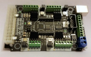
CNC xPRO Driver

Discussion in 'Other Builds' started by Spark Concepts, May 25, 2014.

  1. Joe Santarsiero

    Joe Santarsiero OB addict
    Staff Member Moderator Builder

    Joined:
    Oct 30, 2014
    Messages:
    902
    Likes Received:
    196
    I see that, but I'm not one to say that it is the issue. You should really be contacting spark concepts to see if they'll take the board back and replace it. Let them do a new driver flow and resell the board.
     
  2. solarground

    Builder

    Joined:
    May 27, 2015
    Messages:
    61
    Likes Received:
    9
    Yeah i have contacted and they offered to fix that driver for me but i live in europe and some banks reasons make this unresonable for me to send and receive back the fixed controller and it will take a long long time, so i decided to get a driver and replace the dead one (not i actual but a friend of mine that knows how to do solder will do that)
     
  3. Joe Santarsiero

    Joe Santarsiero OB addict
    Staff Member Moderator Builder

    Joined:
    Oct 30, 2014
    Messages:
    902
    Likes Received:
    196
    okay, but I hope your friend is familiar with surface mounted components. They're a whole different monkey.:D
    Best of luck to you.
     
  4. solarground

    Builder

    Joined:
    May 27, 2015
    Messages:
    61
    Likes Received:
    9
    I hope so :nailbite:
    Thank you! :)
     
  5. Macchp

    Macchp New
    Builder

    Joined:
    Mar 14, 2014
    Messages:
    42
    Likes Received:
    5
    @solarground. Took a picture of mine to compare. It is a jumper.
    Despite the picture quality due to low light, mine seems cleaner, clearly two pads connected and the third not. In your case it is not so clear if the three of them are all connected.
     

    Attached Files:

  6. solarground

    Builder

    Joined:
    May 27, 2015
    Messages:
    61
    Likes Received:
    9
    Thanks for the picture. Yes its doesn' t seem a short, i clear it with a sharp thing now its like yours in the picture. Im waiting to receive my new driver to see if i can replace the bad. But im thinking what can i do to prevent this happening again in the future. The controller is still usable but i dont want to connect the two y motors to one driver. If i cant replace it i will send this to spark to fix it for me. Or maybe i will save it for other project and buy one new controller for my ox. Still i dont know why this happened and how to be on the safe side.
     
  7. solarground

    Builder

    Joined:
    May 27, 2015
    Messages:
    61
    Likes Received:
    9
    Hi,
    i got the controller from the electrician finally, but i think there is no hope. He did total mess. Made wrong and changed a good drv8825 with the replacement. My problem was with Y motor. He changed the A motor and put the A motor's chip to Y motor. Now on the controller work the motors X, Y, and Z but no the A motor with the replaced new DRV8825. I made reset of the board, upload the hex files but no hope :( .
     
  8. Joe Santarsiero

    Joe Santarsiero OB addict
    Staff Member Moderator Builder

    Joined:
    Oct 30, 2014
    Messages:
    902
    Likes Received:
    196
    I'm sorry. Ask him to fix it. You have four good drivers right?
     
  9. solarground

    Builder

    Joined:
    May 27, 2015
    Messages:
    61
    Likes Received:
    9
    Yes i think i have 4 good drivers but Y and A motors dont work. Y motor dont work well and A dont work at all.
    The dead driver was the Y. He changed the A driver that worked and put the replacment driver i give him. Then he mention the mistake and put the A driver to the Y that was dead.
    A total mess. Now the Y driver and motor work but not well, and the A driver seems dead. I m going to send the controller to spark if they can fix it, and i will search for other to order and start the machine work...
     
    Joe Santarsiero likes this.
  10. Joe Santarsiero

    Joe Santarsiero OB addict
    Staff Member Moderator Builder

    Joined:
    Oct 30, 2014
    Messages:
    902
    Likes Received:
    196
    Good Luck
     
  11. solarground

    Builder

    Joined:
    May 27, 2015
    Messages:
    61
    Likes Received:
    9
    Thank you! All beginnings are difficult (proverb we use in my country)
     
  12. Macchp

    Macchp New
    Builder

    Joined:
    Mar 14, 2014
    Messages:
    42
    Likes Received:
    5

    Really unluky.
     
  13. solarground

    Builder

    Joined:
    May 27, 2015
    Messages:
    61
    Likes Received:
    9
  14. wdytam

    wdytam New
    Builder

    Joined:
    Jun 29, 2015
    Messages:
    1
    Likes Received:
    0
    Dear forum,

    I've got a couple of questions and I am wondering if someone is able to help with the following issues:

    *Driving 5th motor with current controller?

    I have assembled an OX CNC kit from openbuilds and it's functional. Using the xpro v2 controller i am able to send Gcode to the machine and it responds correctly.
    The current XYZ movement asks for 4 motors ( 2 for the y-axis). So we can position our machine wherever we want. (see attachment)
    However we need to be able to drive another stepper motor once the position is correct. This 5th motor drives a camera into tubes to visually check their content. These tubes are pretty long (>80cm) so the current Z-axis
    is used to correctly mount the camera into the tube. We were wondering if it's possible to use the cnc xpro controller v2 to drive the 5th motor (camera tube). (Using the 5 or 12V outputs or some kind of additional A1A2/B1B2 connection we can add to the controller?)
    Or do we have to buy a new board that's capable of driving 5 motors?

    * Gcode software

    We are currently using Gcode universal sender to connect to the machine. We were wondering if this software is recommended or you would advise another free software?

    *Gcode

    Now for the code itself. The tubes are located in a circular flange.
    We need to be able to:
    - place the camera above the tube, according to the attached document. How would you locate the first tube (using which reference point?) and then proceed to the remaining tubes (using a subprogram?).
    Or would you use a program to draw the picture and then generate the gcode?
    - place the camera mount close enough ( using the z-axis )
    - send the camera in
    - The camera needs to be able to detect resistance. This can be caused by impurities, filth or the end of the tube.
    When the camera detects resistance it should go a little back and try again to proceed. If this fails three times this means the camera is at the end or the tube or the tube needs to be cleaned.
    -pull the camera back up
    - go to the next tube
     
    #344 wdytam, Aug 10, 2015
    Last edited: Aug 10, 2015
  15. arc1979

    arc1979 New
    Builder

    Joined:
    Sep 4, 2014
    Messages:
    21
    Likes Received:
    0
    I am using the xPro on my C beam machine. The y axis is not working. When I try to move the axis with the software the y motor makes one tick sound and does nothing. I know everything is wired correctly. Any suggestion?
     
  16. R_B

    R_B New
    Builder

    Joined:
    Jul 18, 2015
    Messages:
    70
    Likes Received:
    12
    A few days now since you asked this, but a couple of things that might be worth checking.
    a) That with no power to the board the lead screw is free enough to turn by hand at the motor/screw coupling.
    If not then you have mechanical "binding" somewhere, i.e. a gross misalignment due to incorrect spacing of the nut block or perhaps too much preload on the bearings.
    b) When you first power on the board the motors should "lock" and you should no longer be able to turn them by hand - this is the "hold" current at work.

    I didn't have either of these problems, although other experiences (e.g. 3D printer build) led me to check for these as my C-Beam build progressed, so maybe I just avoided them.
     
  17. R_B

    R_B New
    Builder

    Joined:
    Jul 18, 2015
    Messages:
    70
    Likes Received:
    12
    Hey guys, although my board works it was puzzling me that I had read in a number of places various things about setting the motor current correctly.
    Probably "just a ME thing" but I couldn't find the process for doing this in the docs, so I asked spark-concepts.
    I got a prompt and accurate response - here is the link they sent me;
    https://github.com/Spark-Concepts/xPRO/wiki/2.-Connecting-CNC-xPRO#setting-motor-current

    Given that it is a process for turning down the current until the motor doesn't move it is at least POSSIBLE that some of these "nothing happens" scenarios are a result of just too little current being offered to the motors.
     
    Mark Carew likes this.
  18. superelvis

    Builder

    Joined:
    Sep 21, 2015
    Messages:
    22
    Likes Received:
    1
  19. Joe Santarsiero

    Joe Santarsiero OB addict
    Staff Member Moderator Builder

    Joined:
    Oct 30, 2014
    Messages:
    902
    Likes Received:
    196
    Add up all of the current ratings of your motors then multiply by the voltage of your supply. This will give you a safe wattage.
    Might I recommend a 24v supply though. it'll make your motors a little more snappy.

    Joe
     
    superelvis likes this.
  20. Ronald van Arkel

    Staff Member Builder Resident Builder

    Joined:
    May 7, 2014
    Messages:
    472
    Likes Received:
    245
    Besides that, the 12vDC of that ATX PSU will only give you 13A of juice PEAK! That's just 156W PEAK and about 120W continues. Now, for a simple 3x NEMA17 that would be enough but not for 4x NEMA23 motors at the same PSU.

    Like Joe said, go for the 24vDC PSU, much better and easier on the drivers as well.

    -Ronald
     
  21. John Meikrantz

    John Meikrantz Well-Known
    Builder

    Joined:
    Nov 2, 2014
    Messages:
    169
    Likes Received:
    56
    I use a 400w supply with my Ox build (4x Nema23).

    http://www.amazon.com/iMicro-IM400W-ATX12V-Power-Supply/dp/B002HREGRM

    I always intended to "upgrade" at some point to a larger power supply, but haven't felt the need to yet. Ox performs quite well with the ATX supply.
     
  22. superelvis

    Builder

    Joined:
    Sep 21, 2015
    Messages:
    22
    Likes Received:
    1
    I need help please!! o_Oo_O

    I connect the xPro V2 with USB-cable to my PC.... (2 LED are lighting)
    I donĀ“t connect a ATX or 24V powersuply now (do I need for PC connection?)

    I installed the FTDI drivers from this website http://www.ftdichip.com/Drivers/VCP.htm...
    Then I installed the GRBL Controller 3.6.1 from zapmaker website....

    I cannot get the xpro board to talk to my PC using grbl controller or universal g-code sender.
    In GRBL Controller software I can only choose com3 and not the xPro !?:banghead:

    Please help!! What I am doing wrong??:(:(

    no connection.JPG
     
  23. Ronald van Arkel

    Staff Member Builder Resident Builder

    Joined:
    May 7, 2014
    Messages:
    472
    Likes Received:
    245
    Hello Elvis,

    For communication to the xPRO you don't need a power supply other than the 5v that comes from the USB. Some time ago the designer of the xPRO said that it was better to use G-code sender and not GRBL controller, as it may brick the board (so they say, but never had a problem with them). COM3 IS probably the xPRO, you won't see a name there ;). Set Baud Rate at 115200 and you should be able to connect.

    -Ronald
     
  24. elie

    elie New
    Builder

    Joined:
    Sep 30, 2015
    Messages:
    12
    Likes Received:
    0
    Anyone know what fuse I should put to protect the board?
    Thanks
     
  25. Ronald van Arkel

    Staff Member Builder Resident Builder

    Joined:
    May 7, 2014
    Messages:
    472
    Likes Received:
    245
    Hello Elie,

    What are you connecting to the xPRO? We won't be able to give you an indication unless we have that information.

    -Ronald
     
  26. Jestah

    Jestah Well-Known
    Builder

    Joined:
    Dec 4, 2013
    Messages:
    148
    Likes Received:
    84
    Could we generalise for other boards as well?

    I am assuming the fuse rating for any board is the combined max current draw for each stepper ? So if I was to run 4 DRV8825s at max current (2.2A) then should I run a 8.5-9A fuse and is a fast or slow blow better?
     
    elie likes this.
  27. elie

    elie New
    Builder

    Joined:
    Sep 30, 2015
    Messages:
    12
    Likes Received:
    0
    Hi Ronald

    I am running 4 nema 23 motors from open build, they are rated at 2.8A/phase.
    What can you advise? Thanks
     
  28. Spark Concepts

    Spark Concepts Journeyman
    Builder

    Joined:
    Dec 17, 2013
    Messages:
    131
    Likes Received:
    107
    Evening everyone,

    For Overvolt and Overcurrent protection I would recommend a fuse along with a TVS diode. See wiring diagram below. I would recommend either a 15A Fast blow, or a 10A slow blow fuse. Also would recommend metering your power supplies if they adjustable - some go quite a bit higher than the 24V they are labeled as :banghead:. (Voice of experience here...)

    Here ae some part numbers and links to set this up:
    (FUSE HOLDER) http://www.digikey.com/product-detail/en/01530002H/F068-ND/183337
    (15A FUSE) http://www.digikey.com/product-detail/en/0297015.WXNV/F992-ND/146594
    (TVS DIODE) http://www.digikey.com/product-detail/en/SA24A/SA24ACT-ND/2770385

    Let me know if you have any questions! Oh - this will be a good setup regardless of which board you are using, might have to play with the fuse a bit though but the circuit is the same!

    Thanks,
    Mike xproProtection.jpg
     
    elie likes this.
  29. ChadRat6458

    Builder

    Joined:
    Dec 10, 2014
    Messages:
    93
    Likes Received:
    24
    I am using grbl panel. I was able to jog with it. I tried a g code file that I created in f-carve. Nothing fancy just the letter W. It was suppose to be 2" tall. The machine was trying to make it a lot bigger like 2 feet. I hit the emergency stop button. Now it will not do anything. Tried restarting, rebooting and stuff like that. What ustep do I need to have set? Why was it trying to cut so big? I did not have a router or anything like that running. Thanks.
     
  30. superelvis

    Builder

    Joined:
    Sep 21, 2015
    Messages:
    22
    Likes Received:
    1
    Totday I got my HC-05 XBee Bluetooth Module!:)
    I pluged the XBee on the CNC-Xpro but there is no Bluetooh-signal??:(
    Do I have to enable somthing on the CNC-Xpro board or settings?:confused:
     
    #360 superelvis, Nov 20, 2015
    Last edited by a moderator: Nov 20, 2015

Share This Page

  1. This site uses cookies to help personalise content, tailor your experience and to keep you logged in if you register.
    By continuing to use this site, you are consenting to our use of cookies.
    Dismiss Notice