Welcome to Our Community

Some features disabled for guests. Register Today.

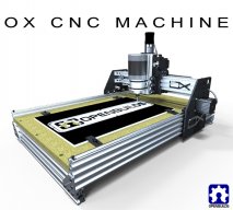
OpenBuilds OX CNC Machine

Discussion in 'CNC Mills/Routers' started by Mark Carew, Dec 15, 2013.

  1. jon wells

    jon wells New
    Builder

    Joined:
    Mar 24, 2015
    Messages:
    4
    Likes Received:
    0
    Hi I just build the open build Ox cnc the small version. I've been trying set it up in grbl panel. I don't even know what to import in the configuration in setting. Can someone help me setup grbl panel. Thank
     
  2. Jestah

    Jestah Well-Known
    Builder

    Joined:
    Dec 4, 2013
    Messages:
    148
    Likes Received:
    84
    Home · grbl/grbl Wiki · GitHub
    Good overview here

    Compiling Grbl · grbl/grbl Wiki · GitHub
    Use this if you need to load GRBL onto the arduino

    Configuring Grbl v0.9 · grbl/grbl Wiki · GitHub
    How to config the latest GRBL if its already loaded on the arduino/board.

    If you are running a CNCsheild (protoneer or clone) Watch out for the Z limit and Spin En pins as they have been swapped in this newer version so some older boards silk screen can be misleading. Do other boards have issues in the change of pinout in the new version?

    I have attached a screen grab of my settings but use with caution as they are only mildly tested on my machine as I run Mach3 99% of the time. I also run NC homing switches so you may need to check that setting if you are running NO switches
     

    Attached Files:

    Tom Allen and Mark Carew like this.
  3. azarock

    azarock New
    Builder

    Joined:
    Oct 11, 2015
    Messages:
    21
    Likes Received:
    5
    I've been planning out my build of a mid sized 1000mm X and Y axis length OX for about a month now; I was wondering if anyone had any input on using a standard nut block on the z axis vs the anti backlash nut block... This is for general purpose materials up to maybe 1/2" mdf/wood, 1/4" aluminum, so not sure if it makes a difference. Anyone have any input on that?

    Just got my order placed for about 95% of my parts yesterday, but was unsure on the above.

    Cheers!

    Edit: I'd also like to thank Mark the OP of this build for his contributions. This build has inspired me to build an OX based machine as well as given me ideas for many other projects including upgrading my 3D printer with more stable parts. Great instructional videos as well.
     
    #2973 azarock, Nov 5, 2015
    Last edited: Nov 5, 2015
  4. Jonny Norris

    Jonny Norris Well-Known
    Builder

    Joined:
    Aug 17, 2014
    Messages:
    491
    Likes Received:
    95
    The less backlash the machine has the better, with anti back lash nut you do sacrifice some speed in the z but it will be faster than you will likely run it.

    Backlash can be a real b***h if you have so I'd personally get the the anti type.
     
  5. azarock

    azarock New
    Builder

    Joined:
    Oct 11, 2015
    Messages:
    21
    Likes Received:
    5
    Thanks Jonny. I'll add one to my next order.
     
  6. azarock

    azarock New
    Builder

    Joined:
    Oct 11, 2015
    Messages:
    21
    Likes Received:
    5
    Here's my initial mock-up. Based on Mark C's design, but all black and 1000mm x 1000mm with a few tweaks. Just the right size for what I'm after. Please excuse my Sketchup skills, I'm still learning (some of my y-axis v-slot faces have disappeared).

    1000x1000 OX CNC Design.JPG
     
    Mark Carew likes this.
  7. autox3d

    autox3d New
    Builder

    Joined:
    Oct 3, 2015
    Messages:
    61
    Likes Received:
    9
    OX mods..

    Im putting together a 4x4 OX as a CNC plasma.

    Mods include using standard Bosch style profile, gantry is 2 pieces 30x60 and gt5 belt 10mm wide.

    I am using 20x40 profile with a plate to join together instead of the 20x80 profile also.

    Import taxes are very high so I need to use as much local manufacture as possible.

    Electronics are USB Mach3 CNC

    4 Axis CNC Mach3 USB Motion Controller Card Interface Breakout Board

    and 4 Sainsmart 3 amp drivers all running at 24v

    Software is Mach3

    Porma Elektronika Torch Height Control.

    I would have preferred to use GRBL but getting the torch height control to work with GRBL will take a lot longer to set up and this machine is needed to run ASAP.
     
  8. R_B

    R_B New
    Builder

    Joined:
    Jul 18, 2015
    Messages:
    70
    Likes Received:
    12
    @Jonny Norris
    I take your point - for some ODD reason I probably hadn't fully internalized the fact that if I am designer, drafts-person and fabricator then there is little/no NEED for dimension-ed drawings.
    Truly a senior moment (-:
    The model's detains are held internally in the model and passed from CAD to CAM (or 3Dprint, which is also CAM).

    I did the tech-drawing/drafting classes with Tee square, set squares, scale rule, templates, curve square (or whatever we called that thing that we joined 3 points with) etc. SO LONG AGO.

    Now there is no need to pass paper drawings to a tool and die maker, or prototype builder , THOSE were the folk that "needed" the drawings.
    I suppose "Approval Authorities" still demand paper with dimensions on EVERYTHING, but maybe they will take model files ONE DAY.
     
    #2978 R_B, Nov 10, 2015
    Last edited: Nov 10, 2015
  9. Joe Santarsiero

    Joe Santarsiero OB addict
    Staff Member Moderator Builder

    Joined:
    Oct 30, 2014
    Messages:
    902
    Likes Received:
    196
    It depends on the job. In 95% of the cases drafts still have to be submitted to who is doing the work. The general rule that it is still up to the fabricators to determine how the part is to be made hasn't changed and the drafter has to keep this in mind. The engineer/designer still has the ability to manipulate this a little though. I tour the local shops whenever I get a chance even if I've toured them previously. This allows me to stay up to date with capabilities among the various other reasons to visit. So, say if a local fab shop purchased a fancy new water jet. I may consult with them first for a job that I designed with a jet in mind. If I find the quote unreasonable I'll fish a little. The point of a draft is to transmit requirements for the part to be made. Flatness of a surface, concentricity of two circles, fit, finish, tolerances, etc, etc.
    It's not the fabricators job to determine intent of a part or model and translate their uninformed understanding into what a draft in hand would tell them. A good working relationship with the fabricators is key. I find that with complex parts or simple parts with key dimensions, being able to go over the drafts together can help both parties significantly and reduce cost.
    Anywho, I've rambled on long enough. I guess the whole point is that it's rare that you'll send a fabricator just a model to work with and this is because they are not supposed to be determining intent. A blueprints purpose is to convey enough information for the fabricator to know what's important, determine on their own how it should be made (even if they send a portion out of house), and how they're going to check it on their end before sending to the customer. If the intent of a part or feature of a part can be conveyed to them verbally along with the draft then this helps both parties involved.
    A draft is essentially a part of the work agreement.

    Joe
     
    Jestah likes this.
  10. Paruk

    Paruk Journeyman
    Builder

    Joined:
    Jul 13, 2014
    Messages:
    397
    Likes Received:
    149
    For who wants to know; 2 out of the 2 Wantai 36V power supplies are failures. 1 DOA the other one has some loose part causing the DC circuit GND to get connected to the AC Earth in the PS. Caused a lot of trouble in tripping limit switches at random, mostly in the middle of the cutting....GRRR. So, be warned for that crap.
     
  11. RomCorrea

    RomCorrea New
    Builder

    Joined:
    Apr 1, 2015
    Messages:
    12
    Likes Received:
    0
    Hey guy. I'm starting to making my ox move (after a long time waiting for parts and having some problems but that's just blahblahblah). What I wanted to ask is if any of you guys think my machine is making too much noise. It sounds like there is something wrong, probably with the configuration but I'm still a bit worried. Not really sure if this is the normal noise but it doesn't sound like it.

    Here is a video of a movement test i was doing. It is short but you can defo hear the noises:


    My configurations so far are these:

    $0=30 (step pulse, usec)
    $1=25 (step idle delay, msec)
    $2=0 (step port invert mask:00000000)
    $3=0 (dir port invert mask:00000000)
    $4=0 (step enable invert, bool)
    $5=0 (limit pins invert, bool)
    $6=0 (probe pin invert, bool)
    $10=3 (status report mask:00000011)
    $11=0.020 (junction deviation, mm)
    $12=0.100 (arc tolerance, mm)
    $13=0 (report inches, bool)
    $20=0 (soft limits, bool)
    $21=0 (hard limits, bool)
    $22=0 (homing cycle, bool)
    $23=0 (homing dir invert mask:00000000)
    $24=25.000 (homing feed, mm/min)
    $25=500.000 (homing seek, mm/min)
    $26=250 (homing debounce, msec)
    $27=1.000 (homing pull-off, mm)
    $100=26.667 (x, step/mm)
    $101=26.667 (y, step/mm)
    $102=200.000 (z, step/mm)
    $110=1000.000 (x max rate, mm/min)
    $111=1000.000 (y max rate, mm/min)
    $112=1000.000 (z max rate, mm/min)
    $120=50.000 (x accel, mm/sec^2)
    $121=50.000 (y accel, mm/sec^2)
    $122=50.000 (z accel, mm/sec^2)
    $130=505.000 (x max travel, mm)
    $131=302.000 (y max travel, mm)
    $132=70.000 (z max travel, mm)

    My OX is 750X500. X/Y use a nema 23 (200 steps/rev) with belt pitch 0.12in (3mm) and a pulley with 20 teeth. Z is a nema 17 (200 steps/rev) with a 8mm threaded rod (2mm pitch). The stepper are set up to 8usteps. I'm using the CNC xPro.

    Any ideas???? Any help is more than welcome.

    Btw, the motors make that noise even when they are not connected to the machine
     
  12. RomCorrea

    RomCorrea New
    Builder

    Joined:
    Apr 1, 2015
    Messages:
    12
    Likes Received:
    0
    I had some problems with my power supply as well. It was shorting. I open it up and the inductor was loose which caused it to spark. Got the thing soldered and it is now working. Might help you. Just be careful.
     
  13. R_B

    R_B New
    Builder

    Joined:
    Jul 18, 2015
    Messages:
    70
    Likes Received:
    12
    @RomCorrea
    To ME that sounds like the motors are skipping.
    I would look for binding , or insufficient current to the motors.

    Can you issue it a command to do a long straight X move, i.e. X motor ONLY driving.
    Then do a long straight Y move.
    If they both sound the same I would guess low current from power supply.
    If different troubleshoot the one that sounds worst.
     
  14. RomCorrea

    RomCorrea New
    Builder

    Joined:
    Apr 1, 2015
    Messages:
    12
    Likes Received:
    0
    They both sound equally bad tbh. The Y is louder cos it is moving more weight and it is 2 moving and not just one.
    I gave that a try with the amps and it didn't really help. If I increase the max rate ans acceleration it solves the problem with it chattering but then the motor seems to run too fast. I had to up it to about 50000 to get it to stop making noise so I imagine there is some sort of configuration that might hit the sweet spot. It would still make noise while at slow speeds:mad:
     
  15. John Meikrantz

    John Meikrantz Well-Known
    Builder

    Joined:
    Nov 2, 2014
    Messages:
    169
    Likes Received:
    56
    I would also change the step pulse - yours is quite high - and leave the idle delay set at 255, which keep the motors always energized. I think that's going to be the default moving forward in grbl anyway.
    Here are my settings, that work pretty smoothly. I also tweaked the driver pots a bit (make sure you are powered off first!) and they are set at between 50 and 75% or so.

    $0=3 (step pulse, usec)
    $1=255 (step idle delay, msec)
    $2=0 (step port invert mask:00000000)
    $3=6 (dir port invert mask:00000110)
    $4=0 (step enable invert, bool)
    $5=0 (limit pins invert, bool)
    $6=0 (probe pin invert, bool)
    $10=3 (status report mask:00000011)
    $11=0.020 (junction deviation, mm)
    $12=0.002 (arc tolerance, mm)
    $13=0 (report inches, bool)
    $20=1 (soft limits, bool)
    $21=0 (hard limits, bool)
    $22=1 (homing cycle, bool)
    $23=3 (homing dir invert mask:00000011)
    $24=50.000 (homing feed, mm/min)
    $25=1200.000 (homing seek, mm/min)
    $26=25 (homing debounce, msec)
    $27=5.000 (homing pull-off, mm)
    $100=26.670 (x, step/mm)
    $101=26.670 (y, step/mm)
    $102=200.000 (z, step/mm)
    $110=7500.000 (x max rate, mm/min)
    $111=7500.000 (y max rate, mm/min)
    $112=1500.000 (z max rate, mm/min)
    $120=150.000 (x accel, mm/sec^2)
    $121=150.000 (y accel, mm/sec^2)
    $122=150.000 (z accel, mm/sec^2)
    $130=510.000 (x max travel, mm)
    $131=770.000 (y max travel, mm)
    $132=170.000 (z max travel, mm)
     
    Mark Carew likes this.
  16. RomCorrea

    RomCorrea New
    Builder

    Joined:
    Apr 1, 2015
    Messages:
    12
    Likes Received:
    0
    That sounds a lot better. :) Still a little noise but I think I'm almost there. maybe just some fine tuning. Just wish I knew what to look for.:ROFL: Gonna get a dial indicator and see how it is doing regarding precision. But thank you very much, it was really a massive help. :thumbsup::thumbsup::thumbsup:
     
  17. Paruk

    Paruk Journeyman
    Builder

    Joined:
    Jul 13, 2014
    Messages:
    397
    Likes Received:
    149
    Thanks, mate. Without exactly knowing (or understanding) what an inductor is I found the problem was exactly that! It was loose and touching the housing of the PS, causing the DC GND to be connected to Earth. Some isolation tape on the inside of the PS housing solved it. Running smooth again!

    (Just googled inductor and found it to be the **** thing!).
     
    Joe Santarsiero likes this.
  18. Mark Carew

    Mark Carew OpenBuilds Team
    Staff Member Moderator Builder Resident Builder

    Joined:
    Jun 28, 2013
    Messages:
    2,758
    Likes Received:
    2,441
    The ongoing controller boards discussion has been added to the controller/driver boards thread. With a group effort I am sure we can find the best controllers for our builds. Thank you for your help
     
    Jestah likes this.
  19. Mark Carew

    Mark Carew OpenBuilds Team
    Staff Member Moderator Builder Resident Builder

    Joined:
    Jun 28, 2013
    Messages:
    2,758
    Likes Received:
    2,441
    Update to the first post of the thread to let everyone know, that along with plates that are offered for the OX CNC machine.
    There are OpenBuild Distributors offering complete OX CNC machine kits!
    Looking for a ready to build OX CNC machine?...

    Complete OX Kits For Sale:
    Here are a few of the awesome OpenBuilds Distributors offering the OX kit in various forums that you can purchase!
    Ooznest - UK based
    SWM3D - US based
    RoboCutters - UK based


    Also added this information to the OX Build page as well.
    Hope this helps and thank you to everyone who has made the OX possible by sharing the news :thumbsup:
     
    #2989 Mark Carew, Nov 20, 2015
    Last edited: Nov 20, 2015
  20. leversole

    leversole New
    Builder

    Joined:
    Nov 1, 2015
    Messages:
    77
    Likes Received:
    14
    What am I missing? Trying to line up the nut plate on the Z axis and it is not aligned, looks like the wheel need an extra spacer, but I cannot find anything other than the normal spacers in the sketchup drawing?!?
     
  21. Ronald van Arkel

    Staff Member Builder Resident Builder

    Joined:
    May 7, 2014
    Messages:
    472
    Likes Received:
    245
    You are using the spacer blocks too I presume? Any photo would help ;).

    -Ronald
     
  22. leversole

    leversole New
    Builder

    Joined:
    Nov 1, 2015
    Messages:
    77
    Likes Received:
    14
    Yes, using the spacer blocks...in a breif spat of "know-it-all-ness", I did not slot the z axis plate mounting holes (that attach to the ends of the rails) I put a slightly oversize (for a small amount of adjustment) hole righ in the center (at 10mm from the edge. Will measure when I take it back apart to see what is what, but I ended up sloting the holes now everything is wirking. Just have to go back and see where I went wrong...trying to follow/combine/redraw the OX 8.1 plates and the OOZnest plates in AutoCad was a journey in itself!
     
  23. Ken Marold

    Builder

    Joined:
    Nov 16, 2015
    Messages:
    2
    Likes Received:
    0
    Do the rail sizes spec'd in the current parts list for this machine build the 2'x4' CNC version? Is it possible to bump the size up to 3'x5' or will it sacrifice the rigidity of the unit?
     
  24. azarock

    azarock New
    Builder

    Joined:
    Oct 11, 2015
    Messages:
    21
    Likes Received:
    5
    The parts list calls for 500mm x 750mm which is ~19.7" x 29.5" which is smaller than 2' x 4'. I'm no structural engineer, but I would think the larger you go the probability to flex more also goes up. I guess it depends on what exactly you are looking to cut/engrave. I am currently building a version which is ~ 39.4" x 39.4" (actual work area is smaller 30" x 32"), which is just a tad smaller then 4' x 4' and seems very stout for the general purpose stuff I'll be throwing at it. I actually wish now that I had started with a smaller one, because this thing is HUGE at the size I decided on.
     
    #2994 azarock, Nov 28, 2015
    Last edited: Nov 28, 2015
  25. Ken Marold

    Builder

    Joined:
    Nov 16, 2015
    Messages:
    2
    Likes Received:
    0
    Thanks for the reply @azarock. Yeah, makes sense. Have you made any structural changes to your system to accommodate the increase in bed size? I do want to make sure that I can work with the full 2' width of material and 4' to 5' of length would be ideal. I'm looking at swapping out the side 20x80 V-Slots for C-Beams and going the full 1500 in length. Could anyone tell me if that would be adequate to solve any flex problems?
     
  26. azarock

    azarock New
    Builder

    Joined:
    Oct 11, 2015
    Messages:
    21
    Likes Received:
    5
    @Ken Marold

    No modifications to mine other than making it bigger. It feels strong enough as is so I'll test it the way it sits before making any modifications to it.
     
  27. Paul Gregory

    Builder

    Joined:
    Oct 19, 2015
    Messages:
    5
    Likes Received:
    1
    You will not regret getting the anti-backlash nut for the z-axis. I wished I had known about it during the original build of my OX. I had to break down the z-axis and rebuild mine, but I do not regret it; since it has eliminated some major issues with the heavy PC router that I have installed on mine.

    Hope your build is going well.
    Paul
     
    Jestah likes this.
  28. davidbrowne

    Builder

    Joined:
    Jul 25, 2014
    Messages:
    30
    Likes Received:
    20
    I've had some trouble with belt slippage lately and thinking of going to a dual belt system.
    Does saw dust and chips cause a problem if it gets in between the two belts and how does one control the problem?
     
  29. Chris Laidlaw

    Chris Laidlaw Well-Known
    Builder

    Joined:
    Mar 1, 2014
    Messages:
    77
    Likes Received:
    27
    I've heard quite a few are using double belts, but you might also try my mount/dust collector combo... Mount and Dust 1.jpg
    at stores.ebay.com/chrisclub1 :)
     
    #2999 Chris Laidlaw, Dec 2, 2015
    Last edited: Dec 3, 2015
    Joe Santarsiero likes this.
  30. chadderuski

    Builder

    Joined:
    Feb 13, 2015
    Messages:
    11
    Likes Received:
    4
    Hi Everyone! Well, I'm back, and no, I haven't built my Ox yet.

    Way back in May I was having troubles with my x-axis being so tight is took two hands to move the head back and forth.

    I have two questions that I hope you guys (gals?) can help with.

    1) What should the outer distance be on the x-axis plates for the wheel holes?

    I measured mine with a decent quality caliper and the front plate has 85mm on both holes, but my rear plate is 84.9 and 84.95.

    2) I bought a new pair of rails from the OpenBuilds store since I had dented the old rails trying to get the z-axis to roll freely. However, the ends are not cut "perfectly" square.
    What are you guys using to get a perfect square end? I don't know if disc sander would be better than trying to re-cut the ends with a chop saw.

    Thanks and in advance for any help or suggestions you have!
     

Share This Page

  1. This site uses cookies to help personalise content, tailor your experience and to keep you logged in if you register.
    By continuing to use this site, you are consenting to our use of cookies.
    Dismiss Notice