Welcome to Our Community

Some features disabled for guests. Register Today.

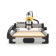
ooznest OX CNC Machine

Discussion in 'CNC Mills/Routers' started by Ryan Lock, Apr 28, 2015.

  1. mel earp

    mel earp New
    Builder

    Joined:
    Oct 12, 2015
    Messages:
    30
    Likes Received:
    17
    Apart from the ply on the top, the rest was made from an old single bed frame that has been stacked up in the garage for years!

    My main target is making toys for the grandchildren. I don't have anything specific in mind but there are loads of ideas and plans around, like 3d slot together models. I did make a counting box for one grandchild and I did all that on my table saw and router table. I was just starting another for grandchild number three, when my wife said "Why don't you make it on the new machine?". So that was a brilliant idea for a starter project! An example of the counters in use attached. And there is a wooden box to hold them (7x100's, 25x10s and 50x1's)

    Longer term I have a hankering to add a rotary axis somehow/somewhere, but that might be a long while off! I need to temper my enthusiasm and make a few things first!
     

    Attached Files:

  2. mel earp

    mel earp New
    Builder

    Joined:
    Oct 12, 2015
    Messages:
    30
    Likes Received:
    17
    Just had enough time to get motors temporarily connected and tested out. Jogging with Chilipeppr and air cutting the test pieces went OK, except for calibration of course. The wiring is scattered all over the place. Need a plan and some real effort to get that right. I can't stand untidy wiring. Still not finally decided whether the controller is going on the deck or on the back of the gantry. I might go for the gantry with a Raspberry Pi (I have a spare) sitting next to it so that the interface to the JSON server is wireless. That way I just have to run power and a few very low power control lines (start, pause etc.).

    I also have attached the spindle and done some measurements on z travel and clearance with the spoiler supports. As it stands, the bottom of the z-axis (not the spindle) touches the spoiler supports at the fully down position. I really can't see the point of this. In normal use there is already the spoiler board itself to put in and that travel is wasted. So that's 18mm which could do with lifting. Then you have to fit the bit in, and I think that for cutting flexibility at least some of the spindle shank should be below the z-axis base, otherwise you are totally limited to the length of the bit.

    All in all I reckon I am going to try lifting the frame by a full 80mm and then experimenting with where the spoiler supports go vertically.

    Of course this is all from a position of someone who hasn't cut anything yet, so if I am talking rot just tell me.
     
  3. Ryan Lock

    Ryan Lock Veteran
    Builder

    Joined:
    Oct 12, 2014
    Messages:
    530
    Likes Received:
    293
    @mel earp I find that mounting it on the gantry makes the wiring a bit easier because there is less moving wires. I used to run mine with a pi and chillpeppr, but switched back to using a laptop and UGS, because i just couldn't get on with chillipeppr.

    Regarding the Z height i didn't have any intentions to mislead anyone with the travels/cutitng depths etc, i am sorry if you feel disappointed. Because of the good points you and dave have raised, i have added a lengthy explanation to the product description.

    With the default setup and a 12mm spoiler board, the absolute max thickness of material that can be cut the whole way through is 26.5mm. There is 65mm of travel on the Z before it will hit the spoiler board supports. There is extra travel to go below the spoiler board supports by 7mm.
     
  4. davestrength

    Builder

    Joined:
    May 29, 2015
    Messages:
    18
    Likes Received:
    19
    I don't think anything was misleading. Just something I didn't realize in advance. The fact is, the Ooznest kit is perfect for first builds. The clear and detailed instructions and mechanical completeness of the kit is perfect for someone who has no experience in building these machines. But along with that inexperience comes a tendency to overlook things you don't understand!

    I think it's also important to keep in mind that the machine is designed around a balance of parameters. Adding z travel height by itself might expose operating conditions that push you beyond this balance. For instance, I can tell you from experience that in the stock configuration, there are limits to slot cutting. Deep slots require more power for chip ejection...and a 1" deep slot can in some instances approach x and y drive power limits (and I'm talking cutting the slot in 1/2 diameter depth passes.) You can work around this with proper CAM (pocket the slot a bit on either side before going full depth), and vacuum or air blasts to aid in chip removal; but it's a limit nonetheless.

    Most of my work thus far has been in solid wood, including some rather hard woods like oak and hard maple. With a 2 flute 1/8" bit, I'm typically running these at 20,000 rpm, 150 inch/min, and 1/16" pass depth. The stock machine excels at these conditions. I'll be attempting some 1/8" aluminum (6061) plates soon...I'll post my results.
     
  5. mel earp

    mel earp New
    Builder

    Joined:
    Oct 12, 2015
    Messages:
    30
    Likes Received:
    17
    Don't get me wrong, I think the kit is superb. I especially like the list of parts for each step. You get the parts for the step out on the bench, follow the step instructions, and if there is anything left on the bench then you have done something wrong. Years ago I built an aircraft (a real one not a model) from a kit and the manual for that was far less comprehensive! You basically got a large bag of bits and had to work out what was what.

    And I don't feel mislead at all.

    Anyway, "disappointment" was perhaps too strong a word. But I did think it odd that I should be starting with a z-travel of 70mm and getting a cutting zone so much reduced from that. I would have thought that 50mm was achievable, and I think it is with a little bit of a tweak. Of course, I wouldn't be expecting to cut a 50mm pocket, nor even cut away 50mm of material. That would be silly.

    So my plan now is to complete the build as standard, get some experience with "flat things" and then see where that takes me.

    Please be assured that my intention is always to share and improve, not to criticise.
     
  6. mel earp

    mel earp New
    Builder

    Joined:
    Oct 12, 2015
    Messages:
    30
    Likes Received:
    17
    Dave, it's good to see that the wood cutting works well. That will be my primary material - Oak, Sapele, Iroko, Idigbo and other bits left over from furniture making.

    I am a bit surprised with the cutting speed of 150 inch/min. That's about 3.8 m/min. Of course I have no idea yet about these settings, but I have looked at vaious calculators including this one (FSWizard - Free Advanced CNC Speed and Feed Calculator) and they seem to suggest much lower feed rates for soft/hard woods, in the range 30-50 inches/min.

    Very interested in the aluminium experience. One or two project ideas might lead me there.
     
  7. OldDogSleeping

    Builder

    Joined:
    Oct 22, 2015
    Messages:
    11
    Likes Received:
    11
    Hi,
    I got my ooznest up and running yesterday :);

    [​IMG]

    Still quite a bit to do but getting there.

    I've started out with a budget control system: Grbl with a CNC Shield and DRV8825 drivers.
    [​IMG]

    If you look closely you'll see I've modified the driver modules;

    [​IMG]

    This is to put them into Fast Decay Mode. Before I made this mod, I found the motor's worked well at speed, but not very smoothly at lower speeds ( say 100mm/min ), and micro-stepping was erratic at best. After a fair bit of research and some careful testing I found that the modules were not managing to make the microstep increases in current, but instead jumping from 0 to full current in one step. Changing the drivers to Fast Decay Mode, fixed this, and with the micro-stepping working correctly I found that 1/32 micro-stepping now provided smoother motion, where as before the mod it made no difference.

    One thing I'm confused by is why so many people have their Grbl settings so slow. I've set my X and Y axis max rate at; 18000 mm/min, and accel at 600 mm/s and it seems easily able to cope with these speeds even at 1/32 micro-stepping and the current limited to 1.5A on the drivers.

    I'm really pleased with how well it's moving now, next job is to make a bench, and then wire it up properly.

    Kevin
     
    #157 OldDogSleeping, Nov 20, 2015
    Last edited: Nov 20, 2015
  8. Ryan Lock

    Ryan Lock Veteran
    Builder

    Joined:
    Oct 12, 2014
    Messages:
    530
    Likes Received:
    293
    @davestrength @mel earp Thanks for the replies, as long as your happy i am happy, which is the most important thing to me :thumbsup:

    As far as i can remember i haven't any feedback regarding cutting aluminium with this machine, so i would like to hear how you get on. I think if your already cutting hardwoods, aluminium should be good as well.

    @OldDogSleeping Great to see another machine built. From conversations from customers who have tried 1/32 micro stepping, it caused accuracy issues when cutting, such as circles not aligning. And when they went down to 1/8 everything worked fine. It will be interesting to see how you get on.
     
  9. davestrength

    Builder

    Joined:
    May 29, 2015
    Messages:
    18
    Likes Received:
    19
    I used a chip load chart with 0.003-0.005" for an 1/8" bit in hardwood. Feed rate = RPM * #flutes * Chip load. So, Feed Rate = 20000 * 2 * 0.003" = 120 " / min. I've been getting decent results with that. I tried running at 20ipm and my steppers and bit both got pretty hot. The steppers stay very cool running at these speeds...and tool life has been good.
     
  10. OldDogSleeping

    Builder

    Joined:
    Oct 22, 2015
    Messages:
    11
    Likes Received:
    11
    Well I've only done a few test cuts, but everything seems fine so far.
    [​IMG]
     
  11. Tom Stratton

    Builder

    Joined:
    Nov 17, 2015
    Messages:
    7
    Likes Received:
    0
    Hi Guys and Gals

    I'm at the point of wanting to commit to a CNC build. It will mainly be for wood working, but also plastics, foams and hopefully thin ali sheets.

    Would someone like to play salesman and tell me why I should have an Ooznest Ox over something like the now infamous X-Carve?

    I have recently made the mistake of reading posts on mycncuk where anything for hobby use using belts is a recipe for disaster and will never work. I hope that this is not the case as I would like to explore CNC, for the 'journey', but don't have deep enough pockets for a pro-scale machine.

    Looking forward to your comments!

    Cheers, Tom
     
  12. Tim P

    Tim P New
    Builder

    Joined:
    May 12, 2015
    Messages:
    34
    Likes Received:
    17
    The Ooznest kit was my first CNC router. I haven't cut anything other than wood but I've been very pleased with this thing. I've had to keep a check on belt tension here and there but honestly they've not given me a problem in the 5 months that I've had it running. There are definitely better solutions than belts but looking at cost vs benefit I'm happy with my choice.

    Edit:
    Here's one of the pieces I've cut recently
    11760152_1629188197368316_8027677469925093506_n.jpg
     
    #162 Tim P, Nov 21, 2015
    Last edited: Nov 21, 2015
  13. cruz1445

    cruz1445 New
    Builder

    Joined:
    Mar 25, 2015
    Messages:
    23
    Likes Received:
    6
    I too, like you, were skeptical about the belt system and stretch. But cost was an issue for me so I made the choice to go with the ooznest. So far I love the things. You definitely have to check tightness of belts here and there and the speed is limited by stretch if your needing close tolerance parts. Ive ran at lower feeds when cutting profiles that I needed precise. Around 45 inches per minute. I did add some pulleys to help with belt skipping on x axis. I think this is a must. This is a great starter machine and have my running daily. The instructions were phenomenal and easy to assemble. Heres a dog feeder I just made all parts and engravings cut on my ooznest.
     

    Attached Files:

    Tom Stratton likes this.
  14. Tom Stratton

    Builder

    Joined:
    Nov 17, 2015
    Messages:
    7
    Likes Received:
    0
    Thanks for the early replies chaps.

    Cruz1445 - wish you hadn't posted this - my wife has just demanded something similar for our two!

    Cheers

    Tom
     
  15. Ryan Lock

    Ryan Lock Veteran
    Builder

    Joined:
    Oct 12, 2014
    Messages:
    530
    Likes Received:
    293
    @OldDogSleeping Great, good to see it is working at 1/32.

    @cruz1445 Wow, really nice work there.

    @Tom Stratton If you are worried about using belts, a few customers i believe have implemented the double belt system on the kit:
     
  16. Tom Stratton

    Builder

    Joined:
    Nov 17, 2015
    Messages:
    7
    Likes Received:
    0
    @Ryan Lock - Thanks for the link. I'm not necessarily worried about single or double belts. I'm trying to gain an understanding of the limitations of the Ox and why I should invest via Ooznest over something like the X-Carve.

    On the 'original' Ox designs, the Y axis plate is only on the outside of the rail, whereas with the Ooznest variant the plate has been doubled to the inside clearly to provide an amount of stability to the wheels, however this appears to be at the expense of lateral (y to y) bracing. How much of a problem is this? How much difference does the lack of y-y bracing make?

    Cheers

    Tom
     
  17. cruz1445

    cruz1445 New
    Builder

    Joined:
    Mar 25, 2015
    Messages:
    23
    Likes Received:
    6
    I dont see where theres an expense to "y to y bracing". Xcarve came out around time I purchased the ox. Only thing I liked were the upgrades it came with, but it looked just like the shapeoko 2 with upgrades. The shapeoko3 looks way more rigid. The rails seemed so small and prone to flex on the xcarve. Also I believe customizations are limited on the xcarve.
     
  18. Tom Stratton

    Builder

    Joined:
    Nov 17, 2015
    Messages:
    7
    Likes Received:
    0
    @cruz1445 because the ooznest y plates and wheels encompass the whole y rail there is no way to provide bracing between the y rails whereas with the usual Ox design the y plate is only on the outside of the y rail allowing cross braces to be inserted... Does that make sense??
     
  19. cruz1445

    cruz1445 New
    Builder

    Joined:
    Mar 25, 2015
    Messages:
    23
    Likes Received:
    6
    Okay yes now I do see now your concerned with racking of some sort without additional support. I havnt had an issue with this. The ox has their own custom Y endplates that brace the y rails together using two 2040 rails on top of eachother making them 2080. After adding the spoilboard supports across I really didnt worry about much racking. If you were wanting to add L brackets to secure the entire machine to a table than this might be an issue due to the plates on eachside of wheels. All in all the Z axis travel was only limiting factor I had. For this I used 2040 spoiler board supports rather thst 2080.
     
  20. mel earp

    mel earp New
    Builder

    Joined:
    Oct 12, 2015
    Messages:
    30
    Likes Received:
    17
    The double belt prototype is very interesting. I quite liked this design years ago when I had an abortive foray into CNC. Now Ryan, the challenge will be to show how to retrofit this to the standard, double plate, Ooznest kit. It was a challenge getting the allen key in to tighten the Y motors, without having to have enough play to tension the top belt!
     
  21. Priit Paat

    Builder

    Joined:
    Jun 18, 2015
    Messages:
    11
    Likes Received:
    1
  22. mel earp

    mel earp New
    Builder

    Joined:
    Oct 12, 2015
    Messages:
    30
    Likes Received:
    17
    I managed to spend another half an hour with my build today. Other stuff getting in the way, so slow going.

    I have it still in temporary wiring mode, but a little temporary shelf on the back of the gantry is stopping stuff from flopping around.

    I have run up against what seems to be a common problem of the motors sounding like woodpeckers. I am powering from a 550w 12 v ATX power supply and have taken GRBL settings for the xPro from SergeE's thread on this problem. No GRBL settings seemed to change anything. I have the xPro power outputs set to about 50%. Varying those made no difference either.

    However, the breakthrough came this morning when I took the advice, again from SergeE, to add heatsinks. I had a couple of power transistor heatsinks, which I cut down to about the right size and just temporarily stuck them on top with some thermal paste. The xPro is currently horizontal so they sat there quite happily. Lo and behold the motors run sweetly, at least for about 50mm at 3m/min feed rate, even up to 4m/min. Further than this and they start pecking again. The xPro is currently in the open air, so no fan, but if I blow on it while performing the move, it just runs nicely.

    What is obviously happening is that there is a rapid sequence of thermal cut out and reset going on, and this causes the pecking and loss of loads of steps.

    It seems to me that heatsinks and a fan are essential for an xPro to work at all. It isn't true to say "you only have to simply wire up your machine to get it working!". So why aren't heatsinks of the right size/shape included, or at least some guidance that this is necessary? Anyway, I shall be on the hunt for a more permanent solution. Any pointers would be welcome.

    And finally, would it be better to trade up to a 24V power supply?
     
  23. mel earp

    mel earp New
    Builder

    Joined:
    Oct 12, 2015
    Messages:
    30
    Likes Received:
    17
    Changing the gantry plates won't of themselves increase the Z TRAVEL. That is a function of the Z axis itself and is fixed at about 70mm. However, if you wish to increase how much of that 70mm is available for your workpiece and what I would call the "cutting zone" then a much cheaper solution is to lower the spoiler board supports by raising the machine, or do what some others have done and use 40mm spoiler supports instead of 80mm. I shall at some point be raising my machine but not before the basic set up is performing well.
     
  24. davestrength

    Builder

    Joined:
    May 29, 2015
    Messages:
    18
    Likes Received:
    19
    It does make sense Tom. You know you have much of the same concerns I had before I purchased and built the kit. I figured I would double belt it...but so far I haven't found the need. Also, concerned about the Y axis flex, I thought I'd cut the inside Y brace plates so that the four top and bottom wheels would be connected. This would allow a gap exposing the middle two slots for attaching braces.

    But, so far, I haven't needed it. I did some tests..and on my machine, which has the largest 1500mm Y axis, if I push with my hand as hard as I can in the middle of the Y axis, I can deflect between 1/32" and 1/16" of inch. And this is a very large force..my body weight leaning into it. The same force to the spindle in the X direction will cause the belt to slip before the Y even moves at all.

    Now, keep in mind, forces of this magnitude are much greater than those that will completely stall the Nema 23 motors included in the kit. So, to me machine flex is not an issue at this point. If I changed the steppers out then perhaps it would become an issue.

    But that brings up some perspective about the machine, which I'm sure you are aware. These are hobby level machines. They're not going to slice through hard metals in 1/4" and 1/2" depth of cuts like you see the $20k machines do on Youtube. But, for the cost, they're very capable machines for wood and plastic, and can be used for some soft metals, provided you baby the depth of cut.
     
  25. davestrength

    Builder

    Joined:
    May 29, 2015
    Messages:
    18
    Likes Received:
    19
    Indeed, I'm going to do Mel's mod here...and swap the lower X-axis spoiler supports for 80's.
     
  26. davestrength

    Builder

    Joined:
    May 29, 2015
    Messages:
    18
    Likes Received:
    19
    Well I spent some time milling aluminum today. That was an adventure! What I learned: when people so you have to go slow with these machines...they mean very, very slow. Like, measuring your travel with a calendar instead of a watch!

    I started out using some chip load calcs with what I figured would be conservative compared to the rates I'd been using for high Janka hardwoods. I set the spindle at 10k for all attempts, and used an 1/8" two flute upcut end mill. I was cutting 6061-T6 aluminum. For mounting, I pre-drilled corner holes and screwed the aluminum plate into the spoiler board so it was rock solid. I occasionally sprayed WD-40 as a lubricant..and used a compressed air blast via a handheld hose to clear chips every so often.

    1st attempt: 60 inch per minute (ipm), 1/16" depth of cut (doc) (~2mm). Result: horrific. Estopped within 10 secs. Terrible chatter. Scary really. Gouged surface and stalled motors so tracking was off.

    2cnd attempt: 30 ipm, 0.04"DOC (1 mm): Result: better...but lots of chatter after several passes. Eventually lost track and started gouging.

    3rd attempt: 15 ipm, 0.02" DOC (0.5mm): Result: smooth cutting, stayed on track...but circles were slightly lopsided. This was my first attempt at circles..so could be more of a CAM issue.

    4th attempt: 15 ipm, 0.005" DOC (0.15 mm) Result: very smooth...to the point where I confidently leave it unattended for a several minutes at a time. Perfect tracking, no lost steps...not chatter at all. I ramped all plunges if possible. Much smoother than slow direct plunges.

    So, what I learned was it is possible to mill aluminum on the Ooznest. IF you go very slow. Throw any of those calculations for maximizing tool life out the window. This is survival mode only.

    In contrast to wood...it wasn't actually too fun! A huge mess...with oil and aluminum chips blasted everywhere from the air. For my circle holes...I just milled pilot / marking spots using the endmill and a shallow drill toolpath. Then I used these as a guide for a step bit on the drill press. That's much cleaner.

    I had some clean up to do with a file as my total depth was too conservative and didn't make it all the way through the plate.

    I think with some toolpath optimizations things could go smoother. Things like pocketing out one side of a profile so the bit isn't trying to slot two sides on every cut would improve the finish. Next time I'll setup some type of "blast shield" to catch all of the aluminum oil slurry that gets blasted off with air. And likely, things would go better with a bit purposely designed for this work.
     
  27. davestrength

    Builder

    Joined:
    May 29, 2015
    Messages:
    18
    Likes Received:
    19
    I had read about this as well...and decided to go ahead and invest in some better electronics up front; mostly I was worried about troubleshooting mechanical and electrical issues all at once. The Gecko G540/Ethernet Smoothstepper / Mach 3 combo has been rock solid in terms of control. Gecko does in fact however recommend air cooling with a fan for anything more the lightest loads. If you're running at 12V, any PC case fan should give you the cooling you need. I'm running 24v, so I had to order a 24v fan.

    As far as 12 vs 24v, in theory you should get better response, at higher torque. Essentially the chopper drive arrives at the motor output voltage and current faster, but at the expense of more heat! So, get your cooling fan in place first. This is a good explanation: Stepper Motor Voltages Explained | The Rising Moon
     
  28. mel earp

    mel earp New
    Builder

    Joined:
    Oct 12, 2015
    Messages:
    30
    Likes Received:
    17
    Very useful link. No need for me to change right now but will consider it later. Now just need to find where I put that fan!
     
  29. John Meikrantz

    John Meikrantz Well-Known
    Builder

    Joined:
    Nov 2, 2014
    Messages:
    169
    Likes Received:
    56
    Yeah, the datasheet for the DRV8825 specifies cooling when driven at 2.5a. Not sure why xpro didn't include. Most of the pololu type step sticks come with heat sinks. I used some copper VGA heat sinks, and that solved the issue. I've run mine at 12v and 24v. Runs fine with 12v, maybe a little more speed with 24v. I kept the 12v in place, because I have an emergency stop wired for the ATX power supply, and I'm too lazy to change it.
     
  30. Ryan Lock

    Ryan Lock Veteran
    Builder

    Joined:
    Oct 12, 2014
    Messages:
    530
    Likes Received:
    293
    @Tom Stratton Regarding the Y bracing, depends on the size of the machine you are after. I would say 1000mm and under it isn't necessary at all. If you would like a 1500mm y axis, our default setup would still work perfectly fine. However once you start pushing the machine and upgrading you always have the option to do what davestrength said, cut our inner plate in half, which will give you the best of both worlds.
    The good thing about the OX, is the that the base machine will work fine in the most cases, but because the machine uses mostly standard parts, switching parts out to customize the machine more suited to your specific needs is relatively easy.
     

Share This Page

  1. This site uses cookies to help personalise content, tailor your experience and to keep you logged in if you register.
    By continuing to use this site, you are consenting to our use of cookies.
    Dismiss Notice