Welcome to Our Community

Some features disabled for guests. Register Today.

Software speed control of a brushless dc (Bldc) motor from Mach3.

Discussion in 'Other Builds' started by Tweakie, May 21, 2014.

  1. David the swarfer

    David the swarfer OpenBuilds Team
    Staff Member Moderator Builder Resident Builder

    Joined:
    Aug 6, 2013
    Messages:
    3,462
    Likes Received:
    1,915
    just a thought, it may be a better 'works everywhere' route to convert the PWM signal to an analog voltage, then let the Arduino read that. then we don't need to know much about the frequency, nor change it, and flat line states won't make any difference to the code.

    what do you all think?
     
  2. Macchp

    Macchp New
    Builder

    Joined:
    Mar 14, 2014
    Messages:
    42
    Likes Received:
    5
    Hi guys, I finished my board for the GRBL version. It is mounted on my OX (xPro V2 + RC M5055 700Kv spindle) and it works.
    I had to modify the GRBL 0.9g sketch (Spindle_control.c) to decrease the PWM frequency and manage the RPM range avoiding a flat 5V signal. Also, I rewrote the PIC program adding additional Pot and Switch to manually adjust the speed (-/+ 25%) while PWM driven.
    Features:
    - GRBL 09.g compatible
    - Manual speed control (0 - 100%)
    - PWM speed control by GRBL Sxxx command (0-1000 range)
    - Manual speed adjust while PWM driven (+/- 25%)


    If anyone is interested, I can put together the bits and pieces I have all around and make them available. Just let me know.
     
  3. Tweakie

    Tweakie OpenBuilds Team
    Moderator

    Joined:
    Jan 18, 2014
    Messages:
    784
    Likes Received:
    326
    Excellent work @Macchp :thumbsup:

    Please consider posting the HEX file and sharing the details so that others using GRBL can complete this as a project. ;)

    Tweakie.
     
  4. luisge

    luisge New
    Builder

    Joined:
    Oct 4, 2014
    Messages:
    6
    Likes Received:
    1
    Hello Tweakie, I hope you can help me, because I tried to reproduce the driver for my spindle, but in my town I can not get the 12F683 and need, please you or anyone can compile the software in this case, for the 12F629 or 12F675, and includ the Hex file in the files secction.
    Thanks in advance!
     
  5. Tweakie

    Tweakie OpenBuilds Team
    Moderator

    Joined:
    Jan 18, 2014
    Messages:
    784
    Likes Received:
    326
    Because of the differences in both the ADC and clock, I am not absolutely certain but, it may not run correctly with the 12F629/675 and may have timing issues.

    Perhaps best to mail-order a 12F683. ;)


    Tweakie.
     
  6. luisge

    luisge New
    Builder

    Joined:
    Oct 4, 2014
    Messages:
    6
    Likes Received:
    1
    That's what I suspected! ... Unfortunately I do not know how to program PIC and I command my spindle under Mach3, perhaps for elegance, or vanity (to proudly display my accomplishments, ha ha ...), I would like to incorporate this facility.
    Well, I will arm of patience and will order the 12F683 ...
    Thanks again for sharing your constructions.
     
  7. luisge

    luisge New
    Builder

    Joined:
    Oct 4, 2014
    Messages:
    6
    Likes Received:
    1
    I want to add:
    I hope to upload my small builds.

    Greetings, luisge.
     
  8. Tweakie

    Tweakie OpenBuilds Team
    Moderator

    Joined:
    Jan 18, 2014
    Messages:
    784
    Likes Received:
    326
    Hi Luisge,

    If you do not have access to one then the standard PIC programmers can be obtained very cheaply via e-bay and the supplied (or downloaded) software is extremely simple to use.

    Good fortune with this my friend and I look forward to seeing your builds.

    Tweakie.
     
  9. Macchp

    Macchp New
    Builder

    Joined:
    Mar 14, 2014
    Messages:
    42
    Likes Received:
    5
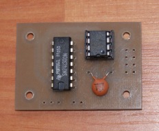
    As suggested by Tweakie, here the files and some explanation on how to use this great project with GRBL 0.9g.
    I'll probably publish a build to go trough all the details much better, but the available time is never enough, so I thought to start making all the files available here.

    First of all you need to be aware that to use it you need to make few changes to the electronic circuit for which I haven't developed any drawing but it is so easy that it should not be any problem:

    1) it is based on the manual/automatic version
    2) need to be added a switch between PIC pin4 (GP3) and ground to enable/disable the manual speed adjust when PWM driven
    3) need to add a 10Kohm resistor between +Vcc and PIC pin4 (GP3 has no internal pull-up resistor, so we need to add it externally)
    4) need an additional pot 10Kohm between +Vcc and GND with the central cursor connected to PIC pin3 (GP4)

    Secondly, we need to slow down the Arduino PWM frequency, so I added a readme.txt file to explain exactly which lines are to be changed. That also mean you need to recompile the GRBL0.9g sketch and reflash the xPro board or any Arduino UNO based board.


    In the zip file, there are also two pictures of the output signal at min and max speed going from 972uSec to 2,07mSec. It should accommodate most of the RC speed controller even if I tested it only with RED BRICK 80A esc and Turnigy PLUSH 30A.


    xproesc8_test_Bench.png xproesc8_mounted.png
     

    Attached Files:

    Mark Carew likes this.
  10. Tweakie

    Tweakie OpenBuilds Team
    Moderator

    Joined:
    Jan 18, 2014
    Messages:
    784
    Likes Received:
    326
    Excellent work @Macchp - I like the idea of the PWM speed trimmer potentiometer. :thumbsup:
    It would be great if you could publish this as a build but I know the feeling - there is never enough time to do everything :)

    Tweakie.
     
  11. frareg

    frareg New
    Builder

    Joined:
    Feb 7, 2015
    Messages:
    2
    Likes Received:
    0
    Great Job and the idea is good.
    I have a ESS (Ethernet Smooth Stepper) ,is that possible to run the circuit with them..

    Frareg
     
  12. Tweakie

    Tweakie OpenBuilds Team
    Moderator

    Joined:
    Jan 18, 2014
    Messages:
    784
    Likes Received:
    326
    No problem, the ESS outputs the PWM in exactly the same way as the parallel port.

    Tweakie.
     
  13. frareg

    frareg New
    Builder

    Joined:
    Feb 7, 2015
    Messages:
    2
    Likes Received:
    0
    Hi Tweakie,
    thanks for the fast answer, OK I have bulid the circuit fast..
    But witch port I need it by the ESS..?

    Frareg
     

    Attached Files:

  14. Tweakie

    Tweakie OpenBuilds Team
    Moderator

    Joined:
    Jan 18, 2014
    Messages:
    784
    Likes Received:
    326
    Excellent job you have made with the circuit board. :thumbsup:
    Assuming you have a free Output on Port 1 then I would use that. The Smooth Stepper user manual gives the setting up details for PWM spindle control. http://www.warp9td.com/index.php/documentation

    Tweakie.
     
  15. luisge

    luisge New
    Builder

    Joined:
    Oct 4, 2014
    Messages:
    6
    Likes Received:
    1
    Hello everyone! Finally, I could make the driver, so I attached several pictures (sorry for the bad quality).
    Thanks and best regards! IMG_20150428_193419.jpg IMG_20150428_193419.jpg IMG_20150428_193351.jpg IMG_20150428_193419.jpg IMG_20150509_011533.jpg IMG_20150428_193419.jpg IMG_20150428_193351.jpg IMG_20150509_011533.jpg IMG_20150509_011548.jpg
     
    Mark Carew likes this.
  16. luisge

    luisge New
    Builder

    Joined:
    Oct 4, 2014
    Messages:
    6
    Likes Received:
    1
    Hi, I am testing the driver and trying to learn about the operation of the ESC and brushless and I am noting that the acceleration is not linear and also not very "clean".
    From what I could see on the web, if I understood correctly, the system operates under the control of a periodic signal of 50Hz, that is 20ms, which includes a pulse from 1ms to 2ms.
    Now, from what I could see with the oscilloscope, in our case the pulse is added to the cycle of 20ms, so the period is now between 20ms to 22ms !!! (?)
    It is that why is behavior that I see as abnormal?
    I wonder if I did something wrong or if someone does so with the behavior of the driver.
    Greetings!
     
  17. Tweakie

    Tweakie OpenBuilds Team
    Moderator

    Joined:
    Jan 18, 2014
    Messages:
    784
    Likes Received:
    326
    Excellent work with the controller @luisge :thumbsup:

    Tweakie.
     
  18. David the swarfer

    David the swarfer OpenBuilds Team
    Staff Member Moderator Builder Resident Builder

    Joined:
    Aug 6, 2013
    Messages:
    3,462
    Likes Received:
    1,915
    the non linearity you are seeing is probably arising in the ESC itself, they are not all created equal, and achieving a linear relation between pulse length and motor speed is actually hard to do (and not really needed for RC aircraft).

    the pulse frequency can be up to 400Hz and the ESC should operate just fine, many multicopter controllers run at 400Hz or near that frequency.

    if you really want it linear, you would have to feed the ESC accurate pulse lengths (say 1ms then 1.1, then 1.2 .. etc up to 2ms) and measure the RPM of the motor for each pulse length, then create a translation table and reprogram the PIC so that it translates the incoming pulse length into the pulse length needed for a particular speed on the linear scale.

    A possibly better way to do it is have the PIC read the actual speed of the motor (from some sort of sensor on the shaft) and adjust the pulse length to maintain the set speed.

    However, keep in mind that any of these techniques will only work for ONE size and brand of ESC and motor combination. If anything changes then you have to recalibrate all of it.
     
    JustinTime and Mark Carew like this.
  19. Mark Carew

    Mark Carew OpenBuilds Team
    Staff Member Moderator Builder Resident Builder

    Joined:
    Jun 28, 2013
    Messages:
    2,758
    Likes Received:
    2,441
    Great work @luisge :thumbsup:
    This turned out very nice
     
  20. turboedgs

    turboedgs New
    Builder

    Joined:
    Jan 13, 2016
    Messages:
    6
    Likes Received:
    0
    Were would one download the build files for this project. A files pages/link doesn't seem to be available, or at least I cant seem to find it anywhere.

    Thanks
     
  21. Tweakie

    Tweakie OpenBuilds Team
    Moderator

    Joined:
    Jan 18, 2014
    Messages:
    784
    Likes Received:
    326
  22. turboedgs

    turboedgs New
    Builder

    Joined:
    Jan 13, 2016
    Messages:
    6
    Likes Received:
    0
    Has anyone compiled a code set for an Arduino or is the only source code for the PIC chip?
     
  23. turboedgs

    turboedgs New
    Builder

    Joined:
    Jan 13, 2016
    Messages:
    6
    Likes Received:
    0
    There isnt any "files" tab to this open build. On the build page there is only, build, review and discussion. Where the source hex files and gcode for the pcb milling removed?
    Thanks
     
  24. Tweakie

    Tweakie OpenBuilds Team
    Moderator

    Joined:
    Jan 18, 2014
    Messages:
    784
    Likes Received:
    326
    For some unknown reason the Files section has been removed from this build.

    Tweakie.
     
  25. David the swarfer

    David the swarfer OpenBuilds Team
    Staff Member Moderator Builder Resident Builder

    Joined:
    Aug 6, 2013
    Messages:
    3,462
    Likes Received:
    1,915
    I am, very slowly. working on an Arduino version....
     
    3DMON likes this.
  26. turboedgs

    turboedgs New
    Builder

    Joined:
    Jan 13, 2016
    Messages:
    6
    Likes Received:
    0
    Bummer...
     
  27. 3DMON

    3DMON New
    Builder

    Joined:
    Nov 8, 2013
    Messages:
    51
    Likes Received:
    22
    Awesome!
     
  28. Mark Carew

    Mark Carew OpenBuilds Team
    Staff Member Moderator Builder Resident Builder

    Joined:
    Jun 28, 2013
    Messages:
    2,758
    Likes Received:
    2,441
    I will look into why this would happen.
    EDIT ok got it it was an error on my part, fixed now and the Files are back now :)
     
    #58 Mark Carew, Jan 18, 2016
    Last edited: Jan 18, 2016
  29. turboedgs

    turboedgs New
    Builder

    Joined:
    Jan 13, 2016
    Messages:
    6
    Likes Received:
    0
    FYI, I found this code to work for the Arduino also:

    #include <Servo.h>

    Servo esc;
    int throttlePin = 0;

    void setup()
    {
    esc.attach(9);
    }

    void loop()
    {
    int throttle = analogRead(throttlePin);
    throttle = map(throttle, 0, 1023, 0, 179);
    esc.write(throttle);
    }

    I used the power and ground from my ESC to supply the Arduino board. I also ran the 5v and ground from the ESC to the pwm (+) and (-) pins on my BOB. The PWM output signal pin from the BOB goes to pin 0 analog on the Arduino and pin 9 from the Arduino to the ESC PWM signal wire.

    I used one of those inexpensive blue servo testers found on ebay to tune the esc prior to connection.

    After making the correct setting selections in Mach3 the spindle turns on/off via the on screen toggle and gcode. I also have speed adjustment through both command methods as well.

    Hope this helps some looking to use the Arduino as a starting point.
     
  30. turboedgs

    turboedgs New
    Builder

    Joined:
    Jan 13, 2016
    Messages:
    6
    Likes Received:
    0
    Yes I have speed control as well. Though I don't have an RPM readout on Mach. You will have to play around with the spindle pulley configuration settings to get your speed range set. I think I have my min speed at 100 and my max at 1000 (these numbers are not actual speed in my case just range of pwm signal, I believe). I am still playing around with this approach so understand my efforts are not perfect and the combo of motor and esc you are using may require different settings during setup?

    All I did was tune my esc's max and min speeds with a servo tester. This involves having the servo tester set to full throttle at power up of the esc. Once energized (per my ESC) I hear two beeps then I then turn the throttle to the min setting on the tester. Another beep follows and the ESC is tuned for the full throttle range of the tester.

    After tuning the ESC I just hooked everything up as mentioned in the earlier post, powered up Mach3 and I have control of on/off and speed adjustment. It isn't perfect as I still need to adjust my spindle pulley configurations a bit more. I have tested both manual toggle button on Mach and in Gcode. Both work for me.

    My original though was to replace the pot on the servo tester with an analog input from 0-5v (what the pot on the servo tester puts out) from Mach. That signal would be processed through the micro controller on the tester into a readable for the ESC. That's really all the Arduion code set in the earlier post is, a servo tester via a pot.

    This link was what I started with.

    How to control a brushless motor through a ESC with Arduino
     

Share This Page

  1. This site uses cookies to help personalise content, tailor your experience and to keep you logged in if you register.
    By continuing to use this site, you are consenting to our use of cookies.
    Dismiss Notice