Welcome to Our Community

Some features disabled for guests. Register Today.

Dream to practical

Discussion in 'CNC Mills/Routers' started by Bob K, Jul 17, 2016.

  1. Bob K

    Bob K New
    Builder

    Joined:
    Jun 2, 2016
    Messages:
    55
    Likes Received:
    20
    Bob K published a new build:

    Read more about this build...
     
  2. Rick 2.0

    Rick 2.0 OpenBuilds Team
    Staff Member Moderator Builder Resident Builder

    Joined:
    Dec 20, 2013
    Messages:
    2,892
    Likes Received:
    1,551
    I have to agree with Justin here, moving the amount of mass that is built into your gantry system with the amount of leverage it will possess due to its height is really not a good idea. Continued rapids will eventually bust the wheel axles due to metal fatigue. There will also be a fair amount of sway which is not going to be helpful in either metal cutting or 3D printing.

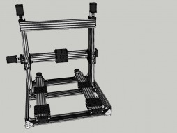
    As an alternate suggestion to achieve the same ends I propose a top-down solution as shown below, a system using a vertical lift platform to bring the work up to the cutter head or lower it away from a 3D print head. This concept seeks to achieve a balance between the rigidity that a cnc machine requires and the finesse a 3D printer requires. The gantry is about the least amount of weight possible and the plywood sides provide the rigidity to keep the system square no matter how much lateral pressure the cutter head imparts on the platform.

    Alt Dream.jpg

    Note the vertical lift system is not shown fully developed. It will require a timing belt connection at the bottom between all the vertical screws to keep them all in sync and of course, a motor to run them. I would also suggest a lower pitch screw on the verticals as it will offer better resolution and less resistance to the motor.

    To complete this, I would probably put it on a wheeled base so it could be rolled to wherever it was needed or out of the way as necessary.
     
  3. Bob K

    Bob K New
    Builder

    Joined:
    Jun 2, 2016
    Messages:
    55
    Likes Received:
    20
    I have no way to calculate/simulate how the system will perform so I'm hoping for feedback from people with experience.

    If I wanted a 12" Z movement I'd need a 705mm extrusion/actuator or about 2/3 of the current height. Is that enough to make you comfortable?

    To make it even worse the stepper motors are about 2x the size of the one sold by OpenBuilds. I'd thought about flipping the Z stepper motors to the bottom but that would require a 170mm tall base. At least I'd have a convenient place to mount the electronics enclosure.

    Bob
     
  4. Jonathon Duerig

    Jonathon Duerig Journeyman
    Builder

    Joined:
    Nov 25, 2015
    Messages:
    261
    Likes Received:
    156
    Ok. Here is a crazy idea. The problem is not really the height itself. It is the fact that the tall and heavy beams/motors are unsupported at the top. What if he had 4 Y-axis beams instead of 2. There would be 2 at the top, 2 at the bottom, and you could attach them all together into a strong box with trusses. Then if you drove it from both the top and the bottom, you would have a much sturdier setup than the current setup.

    At the end of the day, it might be easier and cheaper to make two different machines, though. A CNC router without much Z-travel and rigid enough for cutting. And a 3D printer with lots of X and Y and Z and without nearly as much need of stiffness.

    -D
     
  5. Rick 2.0

    Rick 2.0 OpenBuilds Team
    Staff Member Moderator Builder Resident Builder

    Joined:
    Dec 20, 2013
    Messages:
    2,892
    Likes Received:
    1,551
    Why so massive on the stepper motors? And yes, moving them to the bottom would help. Setting the z-axis rails outside the y-axis rails would simplify this.
     
  6. Bob K

    Bob K New
    Builder

    Joined:
    Jun 2, 2016
    Messages:
    55
    Likes Received:
    20
    On the moving bed design, if I rotate the Z actuators by 90 degrees I'll end up with an x/y movement of about 16" x 16". That's plenty for me.

    moving bed V3.jpg

    I'll go back to the moving bed model.

    I have a few more days before the remaining rails/beams arrive so there's time for further refinements. I'll update the build section then.

    thanks for the help - it's much appreciated

    Bob
     
  7. Bob K

    Bob K New
    Builder

    Joined:
    Jun 2, 2016
    Messages:
    55
    Likes Received:
    20
    Rick - I bought the motors 6 weeks ago when I thought I'd be doing the big fixed bed 1.5M x 1M x 1M. I knew this was bigger than most of the CNC routers so I expected I should have more power (Tim the Tool Man syndrome alive & well here).

    The other thing I liked about them is they only draw 1.8A. That allowed me to use the simpler motor drivers (that plug into my controller) which simplified the wiring.

    Bob
     
  8. Bob K

    Bob K New
    Builder

    Joined:
    Jun 2, 2016
    Messages:
    55
    Likes Received:
    20
    The wiring comment brought up an item I've been wondering about.

    I was REALLY surprised when I saw the wire sizes on the stepper motors and on some of the builds. In my world we'd be using 16 awg for a 2A load that is 1.5M away to be sure that the wiring wasn't a factor. These guys are coming in at 20 awg at the best. Are there any reports of wire size issues?

    I'm going to have to go to a different connector system so I can get contacts that are small enough. Molex has an 0.062" system that has contacts that go down to 30 awg.

    As long as I'm on wiring. Almost everyone has to splice the wires someplace between the controller and the steppers (etc.). I'm a little worried about the splices eventually breaking because the wires are flexed when the machine is in action (every design I've seen has at least one axis this applies to). What types of splices has the community found to be reliable? Solder & heat shrink, but type crimp connectors, 1/4" quick connects, ... ?

    Bob
     
  9. Bob K

    Bob K New
    Builder

    Joined:
    Jun 2, 2016
    Messages:
    55
    Likes Received:
    20
    It just dawned on me what the splice answer is: Don't put the splices in the section that flexes.

    I definitely have a hard time keeping things simple. :(

    Bob
     
  10. Bob K

    Bob K New
    Builder

    Joined:
    Jun 2, 2016
    Messages:
    55
    Likes Received:
    20
    Justin - thanks for the feedback.

    I'll use my over sized (18 awg) wires on the Nema23 steppers and the E3D heater and then probably get 20 awg for the remainder of the signals. I find that anything smaller than 20 awg is as a pain to work with.

    Bob
     
  11. Giarc

    Giarc OpenBuilds Team
    Staff Member Moderator Builder Resident Builder

    Joined:
    Jan 24, 2015
    Messages:
    3,015
    Likes Received:
    1,680
    I had to travel well beyond the length of the wire that was on the steppers so I bought 18/4 stranded shielded wire for about $0.22-ish per foot from Home Depot. Like this: Cerrowire 500 ft. 18/4 Security Alarm Cable-225-1004J - The Home Depot For the limit switches, I uses 18/2 stranded shielded wire. I soldered all connections and covered the joints with heat shrink.
     
  12. Bob K

    Bob K New
    Builder

    Joined:
    Jun 2, 2016
    Messages:
    55
    Likes Received:
    20
    RATSS!!!! - the M5 drill/tap reamed out several of the holes enough that an M5 bolt just slides in & out.

    I can drill & tap them to M6x1.0. The local Home Depot has the needed bolts but they don't match the M5 bolts.

    Anyone know of a source for M6 bolts that are black and have the same head as the M5 bolts?

    Bob

    PS - I also had a couple of problem holes on C-beams. Those I cut shorter & re-tapped.
     
  13. Rick 2.0

    Rick 2.0 OpenBuilds Team
    Staff Member Moderator Builder Resident Builder

    Joined:
    Dec 20, 2013
    Messages:
    2,892
    Likes Received:
    1,551
    I've never found the M5 flat head screws anywhere but here let alone any M6 flat head screws. The closest you will find is button head cap screws which will need to be ground down after installation if you have clearance issues.

    If the reamed out holes are in the ends of the extrusion, just buy some longer screws and go deeper. You can also fill the bad holes with JB Weld and start over as it drills and machines fairly nicely. But if you are using the combo drill bit & tap in a power drill, throw it away. These are designed for tapping thru-holes in plate not for drilling extended holes. The drill bit has to be finished drilling before the threading starts or you will trash holes as the drill bit part doesn't advance as fast as the threading part needs to advance and thus it trashes threads. If you must tap, drill first then hand tap. If you'd like to simplify your world however, just drill the hole @ 3/16" diameter, put a little oil on the end of the screw and run it in, letting it form its own threads. You'll find the grip far more sound than any tap can offer. Just don't use this method on thin plate or on holes you plan to remove and replace the screw more than a couple of times.
     
    GrayUK and Bob K like this.
  14. Bob K

    Bob K New
    Builder

    Joined:
    Jun 2, 2016
    Messages:
    55
    Likes Received:
    20
    Amen to the combo drill/tap in long holes. Just too many problems.
     
  15. Bob K

    Bob K New
    Builder

    Joined:
    Jun 2, 2016
    Messages:
    55
    Likes Received:
    20
    I just did 8 more M5 holes in a piece of V-slot using the drill then tap method. I screwed up the first two holes!

    Guess I got lazy over the years and just turned the tap until I felt increased resistance, reversed the tap a 1/2 turn and then continued. That resulted in aluminum smearing around the leading edge of the tap. If thick enough that smear would remove the thread on the way out.

    Things went considerably better once I went back to "rotate 1/4 to 1/3 turn, reverse for 1/2 turn" and backed the tap out completely 3-4 times per hole. On the way out if I felt increased resistance I'd reverse the tap for 1/2 a turn and then continue. I knew there would be smear if the resistance didn't drop. Usually there wasn't any smear and the smear I did get didn't cause any problems.

    I've never worked with an aluminum that smeared like this one does.

    I've tried getting the JB Weld down the two bad holes. Didn't seem like I got much into the. Tomorrow I'll see if I can drill & tap them.

    I'm now impressed at how good a job the drill/tap did considering it is meant for use with a drill or an impact driver. Definitely not a good method for deep holes.
     
  16. Rick 2.0

    Rick 2.0 OpenBuilds Team
    Staff Member Moderator Builder Resident Builder

    Joined:
    Dec 20, 2013
    Messages:
    2,892
    Likes Received:
    1,551
    Consider getting a forming tap. They are ideal with a malleable material like aluminum and are much easier as all the back and forth motion is eliminated. Just oil the tip and run it in.
     
  17. Bob K

    Bob K New
    Builder

    Joined:
    Jun 2, 2016
    Messages:
    55
    Likes Received:
    20
    I hadn't heard of a forming tap before. Sounds like the pros like them in aluminum.

    There were several mentions that hand threading using a forming tap is nearly impossible. Can it be done with a large drill or an impact driver in a home shop? Just worried that a special device is needed.

    With all the issues I've had, I'll be using a forming tap if I ever need to do a non-trivial number of holes in a future product.

    By any chance did I miss a resource article on machining aluminum? I expect other have had this issue.

    Bob
     
  18. Rick 2.0

    Rick 2.0 OpenBuilds Team
    Staff Member Moderator Builder Resident Builder

    Joined:
    Dec 20, 2013
    Messages:
    2,892
    Likes Received:
    1,551
    I hadn't used the thread forming tap in a while so I gave it a go this morning in a piece of scrap extrusion. The first 10mm were really no big deal but it starts getting fairly snug around the 15mm range. Not really difficult but the monotony of doing it by hand will get to you after a few holes. Might go quicker with an impact driver but I lack an adapter to test.

    The reason I haven't used the forming tap in a while is that I have shifted entirely over to http://www.openbuilds.com/threads/threadforming.1488/. I have a small 12v Dewalt drill/impact driver set and with a 3/16" bit in the drill and the hex screw bit in the driver production is pretty much effortless.
     
  19. Bob K

    Bob K New
    Builder

    Joined:
    Jun 2, 2016
    Messages:
    55
    Likes Received:
    20
    I had a very pleasant surprise today. I decided to cut off the unused portion of a C-beam actuator. When I went to tap the holes I decided to use some of the cutting fluid I'd bought for metal milling. To my surprise the torque needed to run the tap in was obviously lower and there wasn't any smear on the tip of the tap. I then did a few more practice holes with the same result. In between holes I'd spray off the chips with an aerosol can of break cleaner and then I'd dip the tap into the cutting fluid.

    It got me to wondering how the cutting fluid would affect the drill/tap combo. 32 holes later there were absolutely no problems. No smear on the tip and very good looking threads. I then went and ran a 15mm M5 into each hole and torqued it to the point I was afraid I was over doing it. A bolt would last 6-7 holes before I rounded off the hex in the head. I even ran a 10mm into 8 holes with the same result.

    When I used the drill/tap combo I used an impact driver to drive it in without stopping. Definitely less torque needed with the cutting fluid. I did the same clean-and-then-dip-into-the-cutting-fluid between each hole.

    The actual thread engagement was about 4-5mm less than the bolt length because I was putting the bolt through a cast corner brace (about 3mm thick) and there was usually a 1-2mm leadin/shoulder on the hole. I was impressed.

    Cutting fluid is my new best friend.

    Bob

    PS - don't know if it makes a difference or not but the fluid I used was Tapmatic Natural Cutting Fluid Platinum Grade
     
  20. Giarc

    Giarc OpenBuilds Team
    Staff Member Moderator Builder Resident Builder

    Joined:
    Jan 24, 2015
    Messages:
    3,015
    Likes Received:
    1,680
    Yeah, I used cutting fluid on all of mine. I also used it on all the holes I drilled and it really helped when I was drilling and tapping into my lead screws for a more secure connection to the flexible couplers and bearing stops. It makes it so much easier. I used this stuff: 32 oz. Dark Cutting Oil-30204 - The Home Depot I have completed all the tapped and drilled holes on my build and probably haven't even used an ounce. The stuff works very well.
     
  21. Barry Danks

    Barry Danks Well-Known
    Builder

    Joined:
    Apr 21, 2016
    Messages:
    113
    Likes Received:
    36
    Single 22AWG is good for 8 amps...4-6 conductors derate by 80% which comes out to be 6.4A I don't recommend running at max ampacity, but 4 amps is well with in specs which most NEMA23's fall under. Ive been using 22awg 4 conductor flat cable on past few builds and have gotten great results
     
  22. Bob K

    Bob K New
    Builder

    Joined:
    Jun 2, 2016
    Messages:
    55
    Likes Received:
    20
    Barry - where do you get the flat cable & what's the vendor name & part number?

    Four of my steppers are fixed so I can use stiffer cable on them. I'll probably use stranded shielded 20 awg security cable on them. I can get that at Home Depot for 29 cents a foot.

    I've ordered some 24 awg stranded shielded cat5 patch cable to play with. That should be able to handle almost everything else.

    I still have one Nema23 stepper motor and a 2A PWM heater to worry about. Maybe I'll use your flat cable for these.

    You can drive yourself crazy looking for cable. There should be a resource thread on this topic.

    Bob
     
  23. Bob K

    Bob K New
    Builder

    Joined:
    Jun 2, 2016
    Messages:
    55
    Likes Received:
    20
    Newbie question - how easy/hard should it be to turn the 8mm Acme screw?

    I couldn't find anything in the discussion or on YouTube that covered this.

    I've got one that is easy to turn by hand, one that is moderate and three that are hard. The easy one will rotate the screw if I push on it. There's no obvious backlash on the easy one.

    Bob
     
  24. Joe Santarsiero

    Joe Santarsiero OB addict
    Staff Member Moderator Builder

    Joined:
    Oct 30, 2014
    Messages:
    902
    Likes Received:
    196
    Attach a handdrill to the screw and run them in until they loosen up some.
     
  25. Bob K

    Bob K New
    Builder

    Joined:
    Jun 2, 2016
    Messages:
    55
    Likes Received:
    20
    Rick - I received a M5 forming tap and #14 drills today. I did about a dozen holes and have come to these conclusions:
    • cutting fluid is still needed
    • a #14 drill is needed. 3/16" is too big (15mm bolt can't be torqued down) and 11/32" is too small (I was afraid I'd break the tap).
    • a modest 1/2" cordless drill is enough to run the tap in
    I like the drill/tap combo with cutting fluid best of all. It's messier than the forming tap but it does a great job and is easier to obtain.

    Bob
     
    Rick 2.0 likes this.
  26. Bob K

    Bob K New
    Builder

    Joined:
    Jun 2, 2016
    Messages:
    55
    Likes Received:
    20
    Major problem

    My Azteeg X3pro controller isn't compatible with GRBL. GRBL requires some signals to be grouped together in a single port but my hardware has them all over the place.

    I briefly looked at the TinyG series. They're great for CNC mills but I don't see them mentioned in the 3D printer section so I'm assuming they're not compatible.

    My dreams of having a single controller do both milling & 3D printing aren't quite dead.

    Suggestions are welcome.

    Bob
     
  27. Bob K

    Bob K New
    Builder

    Joined:
    Jun 2, 2016
    Messages:
    55
    Likes Received:
    20
    I found out that some people are running Marlin on their CNC mills.

    I'm going to try Marlin for CNC milling. I'm pretty sure that you sacrifice performance but I'm so new at this that I wouldn't be able to tell.

    Looks like there's activity in the TinyG/G2 camp to develop a 3D printer. Maybe that'll bear fruit by the time I outgrow my current controller.

    Bob
     
  28. Bob K

    Bob K New
    Builder

    Joined:
    Jun 2, 2016
    Messages:
    55
    Likes Received:
    20
    Got my Y axis moving today. YEAHHHHHH!!!!!!

    Movement is only at about 25mm/s. BOOOOO!!!!!

    Off I go to learn more about stepper motors.

    So far I've learned that the big boys use 48V and higher and like to shell out big $$$.

    One thing I don't have is an idea of how much torque my application needs. I just ran across a post that looks promising: http://www.openbuilds.com/threads/48vdc-or-24vdc-for-stepper-motors.6734/#post-34750

    Bob
     
  29. Bob K

    Bob K New
    Builder

    Joined:
    Jun 2, 2016
    Messages:
    55
    Likes Received:
    20
    I did my first cut today!!!

    Just a shallow pocket in some scrap wood but it proves that the Marlin printer software can be used for milling. I had to manually edit the SketchUcam g-code before Marlin was happy with it. That could get painful on complicated pieces. I'll probably play with other g-code generators to see if their output's any more compatible.

    I've got the system running at 40mm/s on the X and Y axis. That's sort of consistent with the torque curves I got today for my steppers. The curve stops at 5 revolutions a second with the power at about 20% of the low speed torque.

    I was really surprised that the torque curves for 24V and 48V operation were so close to each other. For half the curve they're within 20% of each other. Probably because, at 17mH of inductance, this motor wants to be operated at about 130V.

    I still have a lot of learning to do on stepper performance in a system. If I try to push the feed rate above 40mm/s it starts to shake, it chatter loudly and the actual speed slows down considerably. What I don't understand is:
    • If the rate is too high, why does it slow down instead of stopping? If I push the feed rate high enough then the steppers just chatter and don't move (to be expected). I'm just surprised there's such a wide transition zone. I'm really surprised that it's not loosing any steps when its chattering. Maybe the motors are starting and stopping very rapidly (high speed torque not enough to move the bed but the startup /low speed torque is enough to move it).
    • When the systems starts to chatter (and move slower) I can press on the carriage with all I can yet the speed doesn't change. If the chatter indicates it's getting to it's max speed then that implies that it's also getting close to zero available/extra power which implies that my putting a lot of force opposing the movement should have a very noticeable effect. If the motors are starting and stopping very rapidly then that would explain why there is apparently lots of power available.
    Another thing I'm scratching my head over is the g-code feed rate is set to 5,000mm/min but the observed rate of movement was about 2,400mm/min (40mm/s). Dropping the feed rate in half slows the system down by half. If it had something to do with the number of micro-steps not matching the steps/mm then my move lengths would be way off.

    Oh well, those are mostly curiosity questions since it appears I have the system fairly close to maximum performance and the performance is more than enough to mill aluminum and mild steel.

    On to building the print head!!!

    Bob

    PS - should have put a tarp under it before the cut. My shop vac just didn't get as much of the chips as I expected during the cut.
     
  30. Bob K

    Bob K New
    Builder

    Joined:
    Jun 2, 2016
    Messages:
    55
    Likes Received:
    20
    What are people doing to set the X/Y/Z zero points and/or how are they getting the work piece squared away to the machine?

    I see a few people using the conductive touch block for the zeroing the Z axis. That looks reasonably easy to do repeatable.

    I'm scratching my head over the X & Y methods.

    Right now it looks like I'll start off just making sure the work piece is big enough to overlap the boundaries and let the machine cut off all the excess.

    But what do I do when I need to modify an already machined piece? With my "skills" I know I'll be wanting to salvage some of my early attempts.

    Bob
     

Share This Page

  1. This site uses cookies to help personalise content, tailor your experience and to keep you logged in if you register.
    By continuing to use this site, you are consenting to our use of cookies.
    Dismiss Notice