Welcome to Our Community

Some features disabled for guests. Register Today.

C-Beam based modular Resin Printer

Discussion in '3D printers' started by Jim S, Jul 20, 2016.

  1. Jim S

    Jim S Well-Known
    Builder

    Joined:
    Jan 2, 2016
    Messages:
    41
    Likes Received:
    37
    Jim S published a new build:

    Read more about this build...
     
  2. Mark Carew

    Mark Carew OpenBuilds Team
    Staff Member Moderator Builder Resident Builder

    Joined:
    Jun 28, 2013
    Messages:
    2,759
    Likes Received:
    2,438
    Love how modular this Builds going to be! Looking good so far @Jim S :thumbsup:
     
  3. Muh_3d

    Muh_3d New
    Builder

    Joined:
    Jul 3, 2015
    Messages:
    41
    Likes Received:
    12
    Looking forward to where you go with this..
     
    #3 Muh_3d, Jul 20, 2016
    Last edited: Jul 21, 2016
  4. Jim S

    Jim S Well-Known
    Builder

    Joined:
    Jan 2, 2016
    Messages:
    41
    Likes Received:
    37
    I've simplified the build vat and mirror assembly considerably. Here's the original concept:
    [​IMG]

    And here's my newer, simplified version:
    [​IMG]


    The next item on my list is to design the interface between the vertical portion of the machine and the flat projector mount. It doesn't seem like there's an obvious way to connect something to the end of a C-Beam. There are the 2 holes that line up with the stepper motor that I could screw to some angle or cube connectors, or 2 more like it on the front of the end-plate (where a cover plate would attach). Otherwise, I'd have to use a joining plate of some kind and hope that I can hit enough holes in the bracket to make a solid connection. What have others done to attach to the end of a C-Beam?
     
  5. Jim S

    Jim S Well-Known
    Builder

    Joined:
    Jan 2, 2016
    Messages:
    41
    Likes Received:
    37
    This is what I was hoping would go smoother. Is there a better way to attach to the end of a C-Beam than these methods?


    [​IMG] [​IMG]
    [​IMG]
    [​IMG]
     
  6. Rick 2.0

    Rick 2.0 OpenBuilds Team
    Staff Member Moderator Builder Resident Builder

    Joined:
    Dec 20, 2013
    Messages:
    2,892
    Likes Received:
    1,551
    Oh, so close....

    Take the one in the last photo and move what you have around to the side of the C-Beam, moving it up slightly to where the bottom faces of both the 20x20 and the end plate are flush. Mirror the assembly on the opposite side.

    Another option would be to take a length of 20x40 and run it across the back face of the C-Beam and then put a couple of transverse lengths of 20x40 as feet at the ends. This would probably be more stable as merely setting feet at the side of a C-Beam doesn't provide a very wide stance for a tall structure.
     
    Mark Carew likes this.
  7. Jim S

    Jim S Well-Known
    Builder

    Joined:
    Jan 2, 2016
    Messages:
    41
    Likes Received:
    37
    Like that, eh?

    Seems obvious now :) I was convinced that it was a puzzle for some reason.

    [​IMG]
     
  8. Rick 2.0

    Rick 2.0 OpenBuilds Team
    Staff Member Moderator Builder Resident Builder

    Joined:
    Dec 20, 2013
    Messages:
    2,892
    Likes Received:
    1,551
    Yes. (actually I was thinking at the sides but same difference.)

    A visualization of the second concept...


    dlp base.jpg
    This should offer a bit more stability.
     
    Serge E., Mark Carew and Jim S like this.
  9. evilc66

    evilc66 Journeyman
    Builder

    Joined:
    Jan 9, 2015
    Messages:
    392
    Likes Received:
    153
    If you still want to mount rails under the C-Beam and attach to the sides (much like you were trying with the first picture with the 90 degree bracket), then look into the Misumi HPTTD5. It's a t-shaped bracket, but is longer so that you get four bolts into both rails. Misumi has a bunch of parts that are compatible with the 20mm spacing of the Openbuilds rails if you need anything that falls outside of the Openbuilds parts offerings.
     
    Jim S likes this.
  10. Jim S

    Jim S Well-Known
    Builder

    Joined:
    Jan 2, 2016
    Messages:
    41
    Likes Received:
    37
    I've already got a few of their parts on my list. My mirror holder will use a pair of their 45 degree angle brackets since OpenBuilds doesn't have anything that isn't square. Brackets - 5 Series, Angular Brackets, 135 degree Angle, 2 Slots|MISUMI|MISUMI USA

    I was scoping out some of their mitered extrusions as braces, too. Plate Brackets|MISUMI|MISUMI USA

    Thanks, all. I really appreciate the tips and tricks!
     
    #10 Jim S, Jul 21, 2016
    Last edited: Aug 2, 2016
  11. Jim S

    Jim S Well-Known
    Builder

    Joined:
    Jan 2, 2016
    Messages:
    41
    Likes Received:
    37
    The design is still coming along nicely.

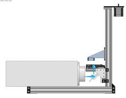
    For those who don't picture what's going on, here's the nickel tour. Basically, the projector will shoot light at a 45 degree mirror to bounce the light upwards into the build vat.
    [​IMG]

    The platform with the mirror and build vat can slide up and down the C-Beam to accommodate projectors of different dimensions.
    [​IMG]

    I designed a subframe under the projector with two adjustable beams so that you can hit the mounting screws on different projectors.
    You can also see how the 45 degree angle brackets attach to the lower beam of the vat assembly in this image.
    [​IMG]

    The frame under the projector is attached to the C-Beam with angle connectors on the top and side, and with a joining plate on the bottom.
    [​IMG]
    [​IMG]

    The joining plate on the bottom will will lay flat because I'm using angle plates of the same thickness in the corners of the sub frame, and I'll just stick rubber pads or something like that onto those plates to clear the screw heads and to give it something to stand on. (side note, I'm surprised that OpenBuilds doesn't sell leveling feet of some kind)
    [​IMG]


    So the next step is to simplify... I overthought and overbuilt the mirror and vat assembly the first time, and now I'm sure that I'm doing the same with the projector subframe. What aspects of the box, the sliding mounting beams, etc could be simplified into a smaller parts count? I want to maintain the universal adjustability, and I don't mind overbuilding it, but I don't want to be ridiculous or overly complicated either.

    The other thing that I have to figure out is which places it makes sense to use cast or extruded angle brackets vs the machined aluminum cubes and wedges. Is there a rule of thumb for which joints to use standard vs deluxe connectors on? I have to use the cubes where I've got 3D box corners, but plain old 90's could go either way...

    Happy Friday, all. I hope you enjoy a nice weekend!
     
  12. Jim S

    Jim S Well-Known
    Builder

    Joined:
    Jan 2, 2016
    Messages:
    41
    Likes Received:
    37
    Here are some simpler views of the entire plan.

    Isometric
    [​IMG]
    Isometric


    Side View
    [​IMG]
    Side View


    Front View
    [​IMG]
    Front View


    Rear View
    [​IMG]
    Rear View


    Top View
    [​IMG]
    Top View


    Bottom View
    [​IMG]
    Bottom View
     
  13. Colin Russon

    Builder

    Joined:
    Dec 4, 2013
    Messages:
    47
    Likes Received:
    24
    I thought resin printers (STL / DLP type printers) needed a laser of some sort to harden the resin, as far as I can see this seems to be using projector light, is that possible?
     
  14. evilc66

    evilc66 Journeyman
    Builder

    Joined:
    Jan 9, 2015
    Messages:
    392
    Likes Received:
    153
    DLP projectors are used all the time for resin printers like this. They need to be modified to be useful though. You have to remove the UV filter and the color wheel (not really necessary on some projectors, but overall it improves the quality). Once the UV filter is removed, then the UV content from the metal halide lamp (usually peaking around 365nm due to the mercury content in the lamp) can pass through the projector and into the resin. It's the UV light that cures the resins typically used in these types of printers.

    LCD's are starting to also be used in resin printers, where the LCD sit directly under the vat of resin. The change here is that the resin has to be able to be cured by blue light (460-480nm) to work, which haven't been all that readily available until recently. Even now, they are still uncommon, and pricey (shipping is killer right now depending on what part of the world you hail from). The cure time is slower due to the limited optical power of the LCD's, but with high resolution and low cost LCDs becoming readily available, 60 second layer cure times is still not that bad when you compare to FDM printers. I'm in the process of making an LCD based resin printer.
     
  15. Jim S

    Jim S Well-Known
    Builder

    Joined:
    Jan 2, 2016
    Messages:
    41
    Likes Received:
    37
    Nailed it, yep. DLP has a good black level, much better than LCD in that part of the UV spectrum, and the resin I use from MakerJuice cures between 365nm and 420.
    Look up the LittleRP and Muve3D, that'll give you an idea of what's going on here.

    My first build was a LittleRP with a $300 Black Friday special Acer projector rated at 3,000 lumens. The minimum projector modifications needed were just for the lense's zoom and focus, and with no other modifications needed I was exposing a layer every 6 or 8 seconds. After getting things up and running, and because I'm good friends with the chemist from MakerJuice, we set up a UV radiometer and started experimenting with other mods like evilc66 mentioned. By removing the UV filter and color wheel, I more than doubled my light output in the UV spectrum and was able to cure layers in 2-3 seconds depending on layer height...

    Anyway, at work we use much larger projectors than the consumer grade toy that my LittleRP is built around. We replace them when they go out of warranty, so I've got 4 dual lamp Panasonics in the 6,000+ lumen range (real lumens, too - not the inflated number on the big box brand) so this projector frame is designed with that caliber of light engine in mind. The 'box' shape that the projector mounts to is a square made of 500mm V-slots, if that helps you scale it.
     
  16. evilc66

    evilc66 Journeyman
    Builder

    Joined:
    Jan 9, 2015
    Messages:
    392
    Likes Received:
    153
    Wow. With that kind of available power, you could probably do continuous printing with the FEP film.
     
  17. Jim S

    Jim S Well-Known
    Builder

    Joined:
    Jan 2, 2016
    Messages:
    41
    Likes Received:
    37
    Trying to finalize the design and BOM today so that we can start ordering things.

    Before I'm committed, maybe in more ways than one, does anyone see glaring errors or obviously over-complicated parts that I should take a second look at? What would you change?

    Since the last update, I've figured out a way to add some leveling feet that I can run into an extrusion T-Nut and then tighten with a jam nut to install Table-Top Bases|MISUMI|MISUMI USA I've modified the lengths of a few pieces on the Vat holder so that I can order them cut to length in whole millimeters, and I've added a pair of handles in an effort to keep people from grabbing the C-Beam to move the machine.
     
  18. Sonny Lowe

    Sonny Lowe Journeyman
    Staff Member Builder Resident Builder

    Joined:
    Nov 11, 2015
    Messages:
    143
    Likes Received:
    158
    Jim,

    I have really enjoyed reading this dialog (I'm learning so much) and watching your printer morph into what it's becoming...it is inspiring me to work on my own, as well as giving me some great ideas ;)

    Thanks for sharing, I look forward to seeing it up and running :)

    Sonny
     
    Jim S likes this.
  19. Jim S

    Jim S Well-Known
    Builder

    Joined:
    Jan 2, 2016
    Messages:
    41
    Likes Received:
    37
    The limitation to continuous printing is more related to the build vat's membrane material than the power of the projector. Each layer that you expose will stick to the vat floor, and most of each layer's print time is actually the mechanical cycle time of raising the build platform to unstick the part, returning it to the right spot for the next layer, and then pausing for a second to let the resin flow and equalize (it's viscous and will bulge the membrane if you go too fast).

    The thing that makes CLIP and some of the other continuous printers revolutionary is that they print without sticking the part to the build vat. This allows them to do a continuous pull without all of the rip and dip that the processes before them required. Other continuous machines print top down and submerge the part as it prints instead of pulling it out of the resin. Both techniques raise questions about their viability. Like I mentioned before, the resin is thicker than water - more like motor oil, and there's speculation on whether or not you could run a continuous print without causing resin starvation on parts of a certain surface area.


    Anyway, last week ended frantically with an unplanned support call from Chicago, and then I was at the MakerFaire in Detroit all weekend, so I haven't finished the design yet. Hopefully the design will wrap and parts will be ordered this week.

    Here're my Detroit MakerFaire pictures, if anyone is interested. The MakerHive - Photos | Facebook The MakerHive is my local makerspace, and I do our social media.
     
  20. evilc66

    evilc66 Journeyman
    Builder

    Joined:
    Jan 9, 2015
    Messages:
    392
    Likes Received:
    153
    I'm in the Detroit area! I really wanted to go to MakerFaire again this year, but schedules with the kids didn't allow. Seeing those pictures really makes me regret not making the time.
     
  21. Jim S

    Jim S Well-Known
    Builder

    Joined:
    Jan 2, 2016
    Messages:
    41
    Likes Received:
    37
    There's always next year. I've gone 3 times now, and it's always amazing. It's a great place to bring the kids, too (depending on their age). Hard to go wrong at The Henry Ford.
     
  22. evilc66

    evilc66 Journeyman
    Builder

    Joined:
    Jan 9, 2015
    Messages:
    392
    Likes Received:
    153
    At 2 and 3-1/2, they may be a little young to appreciate it. But, start 'em young, right? ;) We love going to the Henry Ford Museum and Greenfield Village though.
     
  23. Jim S

    Jim S Well-Known
    Builder

    Joined:
    Jan 2, 2016
    Messages:
    41
    Likes Received:
    37
    Started ordering parts today. I'm pretty confident that it'll at least fit together the way that it looks on my screen. If there are any gotchas or pitfalls in what I've already created, the parts are individually cheap enough that I might as well find out by starting to build it. Pictures coming soon!
     
  24. Jim S

    Jim S Well-Known
    Builder

    Joined:
    Jan 2, 2016
    Messages:
    41
    Likes Received:
    37
    Parts are arriving!! I've got a beautiful pile of aluminum on the workbench, and I'm excited to start taking pictures and assembling them. I also bought a tap/drill set with an M5 in it from harbor Freight and some tapping oil, so it's just about time to start turning some allen wrenches.

    I did have a quantity mixup on some L brackets and a funny motor that I emailed contact(at)openbuildspartstore.com about yesterday, so hopefully I hear back soon. I've never had a bad experience with OpenBuilds though, so I'm sure they'll respond sometime this week and take really good care of me.

    In addition to the OpenBuilds structural parts, I've got a few pieces that were cut to length by Misumi (I want people to be able to build it without special tools or saws), a custom sized mirror from firstsurfacemirror.com, the SeeMeCNC flex-vat and build plate, and the arduino shield from LittleRP. I'll also throw a TMC2100 silent step stick on it, and have been working on the Raspberry Pi NanoDLP image. I'm debating on whether or not it makes sense to add a shutter. Most of the projectors that I intend to use will already have one, but not everybody else's will. I'm trying to find that right balance between being universal and keeping it simple.

    I do still need to order my gear reduction plate from OpenBuilds, but they're not available still. Does anybody have the inside scoop on how soon those might become available again? I know that they're working on adding a bearing, but I don't know what the timeline is... Luckily I'll get by without it, but I do like the idea of removing the flexible coupling, doubling my step resolution, and having a big pulley to turn like a knob for manual positioning (don't really need or care about the torque advantage in this application, a Nema23 is overkill to begin with).

    Anyway though, hopefully my next post will have some pictures and build stories!
     
    Mark Carew likes this.
  25. Mark Carew

    Mark Carew OpenBuilds Team
    Staff Member Moderator Builder Resident Builder

    Joined:
    Jun 28, 2013
    Messages:
    2,759
    Likes Received:
    2,438
    Thank you for the kind words @Jim S :thumbsup: Please excuse the mixup we will take care of it right away. You may may even find a reduction kit in there to help get the build together ;)
    Been following along with your Build an enjoying it very much. Its looking really great and I can't wait to see it come together.
    Thank you for sharing
     
  26. Jim S

    Jim S Well-Known
    Builder

    Joined:
    Jan 2, 2016
    Messages:
    41
    Likes Received:
    37
    That's awesome news, @Mark Carew You guys really are the best!
     
    Mark Carew likes this.
  27. Mark Carew

    Mark Carew OpenBuilds Team
    Staff Member Moderator Builder Resident Builder

    Joined:
    Jun 28, 2013
    Messages:
    2,759
    Likes Received:
    2,438
    Thanks Brother but its guys like you willing to share your Builds with us all that are making the real difference. :thumbsup:
     
  28. evilc66

    evilc66 Journeyman
    Builder

    Joined:
    Jan 9, 2015
    Messages:
    392
    Likes Received:
    153
    :eek: <-- Jealous!!!!
     
    Jim S likes this.
  29. Mark Carew

    Mark Carew OpenBuilds Team
    Staff Member Moderator Builder Resident Builder

    Joined:
    Jun 28, 2013
    Messages:
    2,759
    Likes Received:
    2,438
    My thoughts here were since its not being used for higher torque it can be used for higher resolution. :)
    That being said we could use this as an opportunity to try out these systems for their ability to give a higher resolution on both or your machines.
    So if your interested, we would like to send you a reduction kit as well and see how it works on your SLA Printer Build !:thumbsup:
     
    Joe Santarsiero likes this.
  30. evilc66

    evilc66 Journeyman
    Builder

    Joined:
    Jan 9, 2015
    Messages:
    392
    Likes Received:
    153
    I'd love to try one! I'd also like to try them as a speed up device on the x and y-axis for my C-Beam FDM printer
     

Share This Page

  1. This site uses cookies to help personalise content, tailor your experience and to keep you logged in if you register.
    By continuing to use this site, you are consenting to our use of cookies.
    Dismiss Notice