Welcome to Our Community

Some features disabled for guests. Register Today.

mBOX

Discussion in '3D printers' started by Asaku, Sep 6, 2016.

  1. Asaku

    Asaku New
    Builder

    Joined:
    Jul 14, 2016
    Messages:
    21
    Likes Received:
    10
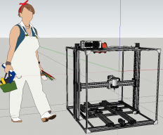
    Asaku published a new build:

    Read more about this build...
     
    Mark Carew likes this.
  2. Anthony Bolgar

    Anthony Bolgar Journeyman
    Builder

    Joined:
    Jan 14, 2016
    Messages:
    354
    Likes Received:
    198
    I like the concept of a versatile multi purpose machine. The only concern I have is the CNC milling function you want to add. It may be able to mill wood and plexiglas0 ( at very low feed rates, and probably not that accurately), but I do not think you will achieve any thing close to satisfactory results trying to mill metal. There is not enough strength and stiffness in the design to allow for the stress metal milling will produce. If you add a laser engrave option, please enclose the machine for safety reasons. a laser diode strong enough to engrave or cut will blind you if it hits your eye, at least with a C02 laser the wavelength is such that you have a chance of fixing any damage done to your eye. As well as enclosing the machine for safety, please always wear laser safe glasses designed for the wavelength of the laser you will be using. I look forward to following this project.
     
  3. Asaku

    Asaku New
    Builder

    Joined:
    Jul 14, 2016
    Messages:
    21
    Likes Received:
    10
    Thanks for your reply Anthony! Yes, the milling part is also my greatest concern. I'm hoping that while in milling mode the Z will be at all times close to the base where it should be much more stiff. X movement in that position should be quite quite well supported by the Z axis's base. I don't think there will be any sort of bending due to the fact that I used 20x40 linear rails and Y wise I added another 20x40 (maybe I'll twick with it some more). But I've never built anything with openbuilds products so I'm not sure about the wheels and how well they resist. I'll keep trying to make it more stiff without needing to rob a bank at the end when I'll estimate the costs. I might also go with 500mm rails instead of 1000.

    Thanks for the advice about the laser. Never worked with one before, I'll make sure to educate myself througly before starting to implement it. Any recommendation about specific hardware is welcome.
     
  4. Asaku

    Asaku New
    Builder

    Joined:
    Jul 14, 2016
    Messages:
    21
    Likes Received:
    10
    *UPDATE* (101)

    - added a platform for the Y axis ~900x770mm reachable area by the head
    - strengthened the X axis based on what I've seen on some other CNC builds
    - added initial concept for the electronics (that's an ATX board mainly because I have a few ones laying around) (yes, that's a 240mm rad)
    - grouped the Y and Z axis for easy movement in sketchup

    Questions for experienced builders:
    - What do you think about the stiffness of the machine? Any way to further improve it?
    - Are 2 nema 23 motors enough for the X axis with direct extruder/mill/laser, etc weight wise?


    On a side note: I might add a notebook screen to act like a monitor and make use of its motion hinges to cover the hardware when it's not in use. (this implies I buy an lcd controller)

    Also, the Z axis requires me to drill 2 holes for the ACME lead screw plate into the middle of the gauntry plates. Any solution that doesn't involve drilling is much appreciated.
     
    #4 Asaku, Sep 7, 2016
    Last edited: Sep 7, 2016
  5. Asaku

    Asaku New
    Builder

    Joined:
    Jul 14, 2016
    Messages:
    21
    Likes Received:
    10
    *UPDATE * (103)

    - changed the X axis movement system by adding 1 more nema 23 motor and integrating the belt into the rail (similar to the OX CNC by @MarkCarew)
    - changed the Z axis with a better version inspired by the actuator kits I've seen in the part store
    - added filament holder
    - initial sketch for an integrated pc + electronics
    - added ventilation system for the extruder

    extruder v103 b.png extruder v103.png front 3d printer v103.png new z axis 2.png spool holder v103.png upper view v103.png x axis v103.png
     
  6. Mark Carew

    Mark Carew OpenBuilds Team
    Staff Member Moderator Builder Resident Builder

    Joined:
    Jun 28, 2013
    Messages:
    2,759
    Likes Received:
    2,438
    Wow looking great! @Asaku keep up the good work :thumbsup:
     
    Asaku likes this.
  7. Asaku

    Asaku New
    Builder

    Joined:
    Jul 14, 2016
    Messages:
    21
    Likes Received:
    10
    Any ideas on how to improve the Y axis? I'm not confident that the Mendel i2 system would be adequate in this situation due to its size and weight (I also want to include a rotating platform in the middle). Also, what material would work for best for the platform? I was thinking about wood but I'm not sure.
     
  8. Julius

    Julius Well-Known
    Builder

    Joined:
    Nov 13, 2015
    Messages:
    193
    Likes Received:
    61
    yea, theres just no way this can do metal unless you put everything into 2080 rails, but you might be better off either:
    A) Making a metal mill, that you can then 3D print with or
    B)make this, and another smaller one for cut wood and metals.
     
  9. Asaku

    Asaku New
    Builder

    Joined:
    Jul 14, 2016
    Messages:
    21
    Likes Received:
    10
    @Julius, thanks for your reply. Could you please elaborate it further? I can't see any "weak" points in the XZ axis if I move the X slowly (the wheels should be full metal). Due to its rectangular shape I don't think there's any risk of bending and due to the double motor setup it should provide sufficient equal force. Or maybe you're saying that the whole structure could wobble under high tension?
     
  10. Asaku

    Asaku New
    Builder

    Joined:
    Jul 14, 2016
    Messages:
    21
    Likes Received:
    10
    @JustinTime extremely appreciated insight. I didn't think about it. Need to revise it a bit. Any wheels you'd recommend?
     
  11. Julius

    Julius Well-Known
    Builder

    Joined:
    Nov 13, 2015
    Messages:
    193
    Likes Received:
    61
    My 2080 Y rails flex if I peck into aluminum more then 0.5mm at a time your 2040 has no chance. My 4080+2080 X has no issue with sag or flex though with the 4lb spindle
     
  12. Julius

    Julius Well-Known
    Builder

    Joined:
    Nov 13, 2015
    Messages:
    193
    Likes Received:
    61
    Xtreme wheels if you do metal. Solid black will do for wood
     
  13. Asaku

    Asaku New
    Builder

    Joined:
    Jul 14, 2016
    Messages:
    21
    Likes Received:
    10
    @Julius, could you be so kind to post some photos with the rails in question with a sign made in paint or some other program indicating the direction in which they tend to bend under pressure? This would really help me improve my mental image of the build. Thank you. (Also, noted the wheels, tnx!)
     
  14. Julius

    Julius Well-Known
    Builder

    Joined:
    Nov 13, 2015
    Messages:
    193
    Likes Received:
    61
    The bend in the opposite direction of the spindle direction, so if I plunge into Z- they move up and away from teh table.
     
  15. Asaku

    Asaku New
    Builder

    Joined:
    Jul 14, 2016
    Messages:
    21
    Likes Received:
    10
    @Julius, I see what you mean. So the Z movement is the problem. I suppose I can increase it to double 20x60. If that doesn't do the trick either I'll go with double 20x80.
     
  16. Anthony Bolgar

    Anthony Bolgar Journeyman
    Builder

    Joined:
    Jan 14, 2016
    Messages:
    354
    Likes Received:
    198
    Amother option would be to use some cbeam extrusion for the X axis
     
  17. Asaku

    Asaku New
    Builder

    Joined:
    Jul 14, 2016
    Messages:
    21
    Likes Received:
    10
    Took you up on that @Anthony Bolgar. I tried to design something that would fit well myself but at the end I realized that @Mark Carew 's design was the best (also taking in consideration that his is tested to work).
    Here is a pic of what I got (the mill isn't fixed on the platform):

    Immagine.png

    This implies I cut some mm off the C-Beam to make it fit between the 2 z-axis beams. Hopefully I can find someone willing and capable of doing this in my vicinity.
     
    Mark Carew and Anthony Bolgar like this.
  18. Anthony Bolgar

    Anthony Bolgar Journeyman
    Builder

    Joined:
    Jan 14, 2016
    Messages:
    354
    Likes Received:
    198
    You can trim the Cbeam with a woodworking chop saw. More theeth the better on the blade.
     
  19. Asaku

    Asaku New
    Builder

    Joined:
    Jul 14, 2016
    Messages:
    21
    Likes Received:
    10
    Hmm... I can't seem to get over something... Could someone tell me what they think would be best for the Z axis? The current Gantry with inside wheels or this exterior version that I brutally chopped off from the OX CNC?
    immagine2.png immagine3.png

    Which should improve stiffness, stability and durability? The first one looks much cleaner but for now my main concern is reliability. Also, the first one uses mini wheels.

    Tnx @Anthony Bolgar for the suggestion. I've seen it done by @Savvas but the problem is finding someone that has one. I'll pay a visit to a FABLAB in my vicinity that might have one.

    Edit: The second option could allow for rotating 180 degrees the Z C-Beams and thus hiding the open ACME Lead screw from potential debris due to milling
     
    #19 Asaku, Sep 18, 2016
    Last edited: Sep 18, 2016
  20. Anthony Bolgar

    Anthony Bolgar Journeyman
    Builder

    Joined:
    Jan 14, 2016
    Messages:
    354
    Likes Received:
    198
    I would definitely choose the outside option, you will acheive a greater degree of stifness. and as you said you can protect the leadscrew.
     
  21. Asaku

    Asaku New
    Builder

    Joined:
    Jul 14, 2016
    Messages:
    21
    Likes Received:
    10
    Definitely an interesting result. Though I've sacrificed some mm from the X movement the overall stiffness of the build seems to have increased due to the added joining plates and the new 20x80 rails on the sides. Also, the fact that the screw is now shielded should increase the reliability by quite a lot.

    immagine4.png immagine5.png immagine6.png immagine7.png
     
  22. Anthony Bolgar

    Anthony Bolgar Journeyman
    Builder

    Joined:
    Jan 14, 2016
    Messages:
    354
    Likes Received:
    198
    This is one of the joys of building using Openbuilds Vslot and accessories, you can tweak the build process throughout the build., as you discover better wys of doing it, either from your own ideas, and a lot of the time, by the remarks of others
     
    Mark Carew likes this.
  23. Asaku

    Asaku New
    Builder

    Joined:
    Jul 14, 2016
    Messages:
    21
    Likes Received:
    10
    You're right @Anthony Bolgar! It's like building with legos but much more complex, thus allowing for everyone to be able to build something at an affordable price due to mass producing of some of the most used parts. Hmm... speaking of affordable... I'll soon need to make my calculations... I started today by considering the basic stuff and I started sweating :nailbite: . Hehehe...

    Back to the subject: I'm not very confident with this Y axis belt system I came up with... I feel like it must be changed immediately but I have literally 0 ideas on how to implement a better one. Any ideas are much appreciated!
    Here are some pics:
    immagine8.png immagine9.png immagine10.png immagine11.png immagine12.png


    P.S. I like the new look of the website! Awesome job MODS!
     
  24. Asaku

    Asaku New
    Builder

    Joined:
    Jul 14, 2016
    Messages:
    21
    Likes Received:
    10
    The last Y design doesn't give me any confidence at all (the belt seems too long the way I put it) so I decided to experiment with something else. Many people seem to love C-beams and I've seen in some videos that they can be pretty fast so I tried designing something that would fit well with the dimensions. After some tweaking I came up with this design:

    immagine13.png immagine14.png immagine15.png immagine16.png immagine17.png

    Yes, the central C-beam sticks out of the frame. I'm considering shortening it. I also had a 2 motor design in my head which would reduce the height and be more sturdy in the Y movement but less in the X-Z.
    This seems like an interesting solution but again, I don't have much experience so any advice is much appreciated.
     
  25. Asaku

    Asaku New
    Builder

    Joined:
    Jul 14, 2016
    Messages:
    21
    Likes Received:
    10
    Changed it again. Browsing some other builds I've stumbled upon @Bob K 's. I've noticed that his was pretty much similar to mine in therms of objective and structure. I thought about putting 2 motor driven c-beam actuators too for the bed at first but scrapped the idea in favor of a single motor design. But after watching @Bob K 's, I decided to give it a try since it had some things that I really liked about it. After some tweaking I made it into a single motor design with 2 c-beams. Oh, and I also meddled with some cable management while I was at it. here are some pics with the build so far:
    bed back.png bed front.png exctruder back.png extruder front.png extruder lat.png front.png gen.png

    Here's some cable management:

    cable management.png

    I'm still experimenting with the pc part, apparently the more I think about it the crazier I get. I might just build a full fledged pc case with transparent plexiglass on top of the mBOX. Still need to think about it but for now the main objective is the mainframe, pc modding comes second. upperview.png


    P.S. Cleaned and updated the sketchup model. Please check it out and tell me your thoughts on it :)
    Edit: dunno why but I can't upload the sketchup model. It says: "security error". Will retry later on.
     

    Attached Files:

    #25 Asaku, Sep 25, 2016
    Last edited: Sep 25, 2016
    Mark Carew likes this.
  26. Bob K

    Bob K New
    Builder

    Joined:
    Jun 2, 2016
    Messages:
    55
    Likes Received:
    20
    Agreed - single actuator is much simpler and doesn't have the possibility of getting out of sync. I'm thinking of going to a single central Y actuator and two outside supports so the bed doesn't tilt.

    The coupler on one of my Y actuators came loose and I didn't notice anything until the threaded rod came out of the actuator (the other Y was pushing it). The speed of the bed was the same so it looks like the second actuator's contribution is negligible. I didn't try a single actuator while cutting so maybe there is still some hope for the dual Y configuration.

    My bed speed is limited by the speed of the steppers. There's very little difference in the max stepping rate with the stepper on the bench and in the system. Looks like I happened to get high power, low speed steppers.
     
  27. Asaku

    Asaku New
    Builder

    Joined:
    Jul 14, 2016
    Messages:
    21
    Likes Received:
    10
    Hi @Bob K ! Happy we agree on the single stepper design. Interesting idea with the side supports for the bed (I have a half idea of how that might be implemented while keeping the clean cable management layout. This should also solve one of my concerns in regard to the front of the Y axis sticking too much out). Also, since our designs are so similar, could you please tell me of any other problems you have encountered since you've built it?

    You might want to take a look at the smoothieboard with external motor drivers (that's what I'm looking at) in case you're not supplying enough current (25mm/s is not exactly what I have in mind). The smoothie also supports lasers!
     
  28. Bob K

    Bob K New
    Builder

    Joined:
    Jun 2, 2016
    Messages:
    55
    Likes Received:
    20
    With 23HS41-1804S steppers I'm running reliably at 35mm/s. I picked those steppers because they were low current & high power. Just didn't realize how slow they were.

    Before buying your steppers insist on getting the torque curves for them. If you push hard enough then even the low cost eBay people will supply them.

    On the single Y actuator - I know I saw a design on OpenBuilds that used linear bearings as the outside supports for the bed. Just can't find it today.

    I'm running an AzteegX3pro. The low current steppers allowed me to use the on board stepper drivers and made for a much cleaner build. I selected it because I was naïve, it had all kinds of stepper drivers, had great 3D printer support and was moderately priced. Now that I see how much I've spent on the project I'd have considered more expensive controllers..

    To get higher speeds I expect you'll end up running 3-4A steppers at 24-48V. That usually means TB6600 drivers. There's been lots of complaints of the TB6600s failing at 48V even though some websites advertise them as 48V units. Mine say 9-40V on the case. I expect that you could buy a 48V supply, adjust it down to 40V and be in good shape.

    You'll definitely want a dust shoe. They're better at getting the chips/dust than chasing it with a vacuum.

    If you have a dust shoe then you'll want to extend the spoiler beyond the cutting area. If not then the shoe will extend beyond the board and won't do a good job of keeping the chips/dust contained.

    I've attached a photo of my current setup.

    The reason why people suggest separate machines for CNC work and printing is that you usually won't have good performance for both in one machine. You'll need stiff/heavy for decent CNC performance but that means slow so the 3D printing performance will suffer. If you want both then expect to shell out big $$ for 48V (or higher) steppers and drivers.

    How big of a 3D print footprint do you want? Maybe some looking in the 3D printer section will give you some idea of the usual sizes. I have a 13" x 13" single heater board. It draws 15A at 24V. You'll need to look carefully at what your controller can support.

    You may want to reconsider how you're mounting the X axis to the Z gantry. Your design requires precision cuts for the top brace, the bottom brace and the X axis actuator plus knowing how much shorter to make the X axis actuator. My method isn't as pretty but it's easier to build & align.

    40x80 Cbeam actuators are the way to go for milling. You'll definitely want to turn the slot away from the cutting action or you'll have to clean them. That would be a problem for the Y carriage because it's mostly covered by the spoiler. I saw a cover in one of your sketches. They aren't long enough to cover the actuator and are only a partial solution.

    If you have a table saw then you can do your own cutting of the aluminum rails & beams. Just head over to Harbor Freight and get their metal cutting 7 1/4" blade (item 62736).

    I expect you'll also want to use 20x80 on the bottom rails that the Z gantry attaches to. The wider the Z gantry mounting points the stiffer the system.

    I don't think the 20x20 rails contribute much to the stiffness. They do make it easy to mount the electronics but they get in the way of moving material to/from the spoiler and attaching to the spoiler. Hmmm - If you could come up with some cross bracing on the rear sides and the back then you'd have much better stiffness at the top.

    Will you need to move your machine through interior doorways? Looks too big.

    You'll want this on top of a table. You'll be spending way too much time building, setting up & learning to be bending over all the time.

    You made a comment about just running slower. That's probably not an option for aluminum. Several sources indicate that aluminum likes feed rates in the 1000 - 2000 mm/minute range. I can verify that 500 and lower with cheap end mills is a bad combination. I'm waiting on a new collet before playing with aluminum again.

    Oh - look at End Mill Discount - Carbide End Mills, Extra & Extra Long Mills, Micro Tools, Thread Mills for your end mills. 3 flute 1/8" mills are only $4-$6. The 10 for $10 ones on eBay are OK for initial learning on wood & plexiglass. Once you've broken all of them you'll probably be far enough along the learning curve that you'll appreciate the more expensive ones.

    I saw a comment about wanting to do 3D scanning. I haven't found a good low cost (under $200) system. I've tried the Microsoft Xbox & Kinect sensors with poor results. Handheld is definitely NOT the way to go.

    The Smoothieboard is a good choice. Last I heard it had great CNC firmware and so so 3D printing. I'm not aware of any other option that is available now that intends to support both CNC milling and 3D printing. The TinyG camp is working on adding 3D print features. See GitHub - synthetos/g2: TinyG2 - The Next Generation

    If I ever decide to go to a faster controller then the Smoothieboard looks like a good option.

    I didn't see anything in the Smoothieboard docs or forums about using the r (radius) form of the G2 & G3 commands. Right now SketchUcam will output some of the G2 & G3 commands with the r form rather than the IJ form. The next release will output in just the IJ form.

    I've been running Marlin for my CNC work. Not ideal but works for me.

    You mentioned quickly changing heads. If you go over the docs page on my build and take a look at the file tool quick change.zip. It shows the system that I came up with.

    Bob
     

    Attached Files:

    #28 Bob K, Sep 28, 2016
    Last edited: Sep 28, 2016

Share This Page

  1. This site uses cookies to help personalise content, tailor your experience and to keep you logged in if you register.
    By continuing to use this site, you are consenting to our use of cookies.
    Dismiss Notice