Welcome to Our Community

Some features disabled for guests. Register Today.

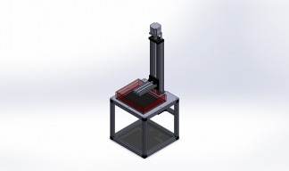
LCD Based SLA Resin Printer

Discussion in '3D printers' started by evilc66, May 3, 2016.

  1. evilc66

    evilc66 Journeyman
    Builder

    Joined:
    Jan 9, 2015
    Messages:
    392
    Likes Received:
    153
    I'm not too worried. These displays are so cheap I don't mind wrecking one or two for the sake of progress. The first LCD was sacrificed for the knowledge of how to take it apart, and what's inside. I have two more working LCDs waiting in the wings.
     
  2. Oneminde

    Oneminde New
    Builder

    Joined:
    Jan 24, 2016
    Messages:
    59
    Likes Received:
    6
    "Sometimes in order to create one must first destroy"- Prometheus. You are absolutely correct. I realise that the task at hand - if that indeed is the task - of revealing and separating the layers is a difficult one, but what if. What if can take you or us a long way. Perhaps push the boundary's of SLA high quality without breaking the bank. Its just a what it, that's all.
     
  3. evilc66

    evilc66 Journeyman
    Builder

    Joined:
    Jan 9, 2015
    Messages:
    392
    Likes Received:
    153
    That's the goal my friend. Make it simple. Make it affordable. Make it high resolution.

    You have to crack a few eggs and all that...
     
  4. evilc66

    evilc66 Journeyman
    Builder

    Joined:
    Jan 9, 2015
    Messages:
    392
    Likes Received:
    153
    Well, caution was just thrown to the wind. Just ordered a 15.6" 4K LCD and controller.
     
    Oneminde and Paul Stoller like this.
  5. Oneminde

    Oneminde New
    Builder

    Joined:
    Jan 24, 2016
    Messages:
    59
    Likes Received:
    6
    The Ebay package ?
     
  6. raymondmuecke

    Builder

    Joined:
    Oct 12, 2016
    Messages:
    3
    Likes Received:
    0
    you are so awsome. i read the last week much about lcd because i will bild the same but with a galaxy tab 2 display.
    but you got much more input as me. i am very interrested on this idea .
     
  7. evilc66

    evilc66 Journeyman
    Builder

    Joined:
    Jan 9, 2015
    Messages:
    392
    Likes Received:
    153
    Yup.
     
    Oneminde likes this.
  8. evilc66

    evilc66 Journeyman
    Builder

    Joined:
    Jan 9, 2015
    Messages:
    392
    Likes Received:
    153
    Thanks for the kind words

    Are you just looking to use the LCD from the Tab2, or will it still have the digitizer attached (or even just the whole tablet)? You probably don't want to use the digitizer over the LCD as it reduces the intensity from the backlight, as well as reducing accuracy as the LCD will be further away from the vat and build surface.
     
  9. raymondmuecke

    Builder

    Joined:
    Oct 12, 2016
    Messages:
    3
    Likes Received:
    0
    did you find anywhere a shop where we can buy now Daylight resin in small package ? i dont find a shop for some tests ( small bottles)
     
  10. evilc66

    evilc66 Journeyman
    Builder

    Joined:
    Jan 9, 2015
    Messages:
    392
    Likes Received:
    153
    Well, some of it depends on where you are in the world. For me, being in the US, I have found Bucktown Polymers, and Photocentric3D. I'm not sure if Bucktown Polymers will ship outside of the US, but their selection is limited for the hobbyist. They have tons of options if you want to buy it by the drum though. Photocentric has distributors globally, so that's a better option. ONO is also offering daylight resins for their printer that they Kickstarted. I don't think the resins are currently for sale outside of Kickstarter, but I'm sure they will be soon.

    If we can get the LCD to pass a moderate amount of shortwave blue light (400-430nm) after some modifications, then that opens things up to UV resins that would be used with DLP style printers. Resins like Makerjuice' G+ will cure at 420nm quite readily, albeit slowly. Unfortunately, we just don't know yet whether the LCD will pass reasonable amounts of shortwave blue light.
     
  11. Oneminde

    Oneminde New
    Builder

    Joined:
    Jan 24, 2016
    Messages:
    59
    Likes Received:
    6
    400-430 nm is limited via the blue filter. If the RGB filter can be removed all together, frequency limitations should not exist any more.

    I wonder if I should email LG and ask if the LG LP156UD1-SPB1 / SPB2 can be delivered without the RGB. Its a long shot.
     
  12. evilc66

    evilc66 Journeyman
    Builder

    Joined:
    Jan 9, 2015
    Messages:
    392
    Likes Received:
    153
    You may want to sit down for this.

    I was poking around in the datasheet for the 15.6" 4K display that I ordered last night (link), and came across some very interesting information.

    First up, the backlight is white and red. Never seen that before, but I can see where it can be useful for increasing the color gamut of the display while maintaining brightness. This isn't really a big deal for our uses. Second up is the fact that this LCD has RGBW pixels!!!! It looks like the "white" pixel (most likely just a pixel that has no color filter) is there to help increase brightness of the image without oversaturating colors. This could be very awesome. The cost of the LCD panel is unfortunately out of the realm of "**** it, I'll buy a new one" if I break it (about $115 each shipped), so I'm a little more nervous about opening it up. BUT, if this really does have a pixel with no color filter, then this might just be the secret sauce we need.
     
    Paul Stoller likes this.
  13. Paul Stoller

    Paul Stoller Journeyman
    Builder

    Joined:
    Feb 28, 2016
    Messages:
    157
    Likes Received:
    107

    That's potentially great news, I'm anxious to see what you find.
     
  14. evilc66

    evilc66 Journeyman
    Builder

    Joined:
    Jan 9, 2015
    Messages:
    392
    Likes Received:
    153
    Me too. A coworker of mine has a pretty good USB microscope that I hope to use to peer into the pixel matrix to see if the mysterious "white" pixel actually exists. Now I just have to not lose my mind as I wait for it to get here (slow boat China Post, so 3-4 weeks if I'm lucky)
     
  15. Oneminde

    Oneminde New
    Builder

    Joined:
    Jan 24, 2016
    Messages:
    59
    Likes Received:
    6
    Excellent news, might be very useful. Remember that since we can only use the B filter, we essentially only have 1 subpixel for the entire RGB or RGBW pixel area. If what you say is true, then our focus should be on that W pixel instead since that one is probably transparent to UV. I'll check the link you provided.
     
  16. Oneminde

    Oneminde New
    Builder

    Joined:
    Jan 24, 2016
    Messages:
    59
    Likes Received:
    6
    Top Left. I wonder if it is transparent or if there is white colour added.
    [​IMG]
     
  17. evilc66

    evilc66 Journeyman
    Builder

    Joined:
    Jan 9, 2015
    Messages:
    392
    Likes Received:
    153
    "White" color would only diffuse the light, not filter it, which wouldn't make sense. They also wouldn't use a phosphor conversion seeing as the primary backlight is white already. I'm pretty confident that the subpixel is transparent. The only other limitation may be in the polarizer. If the polarizers have a cutoff point above the UV limit, then that may be problematic.
     
  18. Oneminde

    Oneminde New
    Builder

    Joined:
    Jan 24, 2016
    Messages:
    59
    Likes Received:
    6
    You might be right, in both statements. My 2 cents: I don't think the polarizing films have UV blockage in them, there is no need to block UV light from an LCD since no UV is generated.
     
  19. evilc66

    evilc66 Journeyman
    Builder

    Joined:
    Jan 9, 2015
    Messages:
    392
    Likes Received:
    153
    Right, but if it's cheaper to make a polarizer that just happens to block UV, then that's what they are going to use.

    Anyway, 100 365nm 3W LEDs have been ordered. This will be set up in a 7x13 array spaced 1" on center. It's a hair smaller than the active area of the panel, but with an inch or two of spacing behind the panel, it should be plenty to get decent performance at the edges. This is all dependent on whether I'm feeling ballsy enough to open it all up :nailbite:
     
  20. Oneminde

    Oneminde New
    Builder

    Joined:
    Jan 24, 2016
    Messages:
    59
    Likes Received:
    6
    he he, I understand. Take your time with the LCD and don't rush things. Do I understand you correctly if you continue with the edge light solution as per normal compared to the version were led's + reflectors + lens underneath the LCD is used ?
     
  21. evilc66

    evilc66 Journeyman
    Builder

    Joined:
    Jan 9, 2015
    Messages:
    392
    Likes Received:
    153
    Finding UV LEDs at a decent price is a challenge all by itself (I paid $126 on AliExpress for 100 365nm LEDs of questionable quality). Finding side emitting UV LEDs for a reasonable price is near impossible (and the cost would have been triple or quadruple the cost of the LEDs I bought with 1/4 the output). Plus, I have no idea what format the LEDs are, but they are most likely the same as the LEDs used in the iPad display seeing as both are made by LG (I had looked them up, but I don't remember what style/size they were). Opening the back up and using a higher power array will be the most practical method. This will allow for substantially higher output and better thermal management.

    No reflectors or lenses here. I'd rather utilize the wider emission angle of the LEDs to create more uniform output at the LCD. I will outline the perimeter of the heatsink with a baffle that will reflect light back into the working area of the LCD. That will add to the safety of the whole printer, as well as scavenging stray light to be put to more useful purposes. The height of the baffle will also help set the distance of the LEDs to the LCD.

    For those looking for high quality heatsinks, check out HeatsinkUSA. Tons of different profile options from 0.601" to 12", cut to any length you want. I've been using these guys for years for my aquarium related LED lighting projects.
     
  22. Oneminde

    Oneminde New
    Builder

    Joined:
    Jan 24, 2016
    Messages:
    59
    Likes Received:
    6
    I wonder how much energy is lost during passage through the polarizing films. Each polymer used have a unique energy interaction level. When - you - have some data on this, fine tuning the watt / led will be much simpler.
     
  23. evilc66

    evilc66 Journeyman
    Builder

    Joined:
    Jan 9, 2015
    Messages:
    392
    Likes Received:
    153
    Well, I think we can all agree that the more the merrier is applicable when it comes to reducing cure times ;)

    I wonder how much the various films degrade over time when exposed to UV? It can't be good for them long term, especially at the intensity levels I plan on throwing at them. One way to find out :)
     
    Oneminde likes this.
  24. Oneminde

    Oneminde New
    Builder

    Joined:
    Jan 24, 2016
    Messages:
    59
    Likes Received:
    6
    All very good questions.
     
  25. ih8lag

    ih8lag New
    Builder

    Joined:
    Sep 8, 2016
    Messages:
    6
    Likes Received:
    1
    My guess is the white pixel your are seeing is for HDR on the new 4K displays essentially an extra 2 bits for brightness and contrast in the display. If this is the case all software will have to be modified for the HDR spec and the controller will have to support it as well as the video card.

    To pass maximum light in that theory you would be displaying a 4k HDR all white image at maximum intensity.
     
  26. evilc66

    evilc66 Journeyman
    Builder

    Joined:
    Jan 9, 2015
    Messages:
    392
    Likes Received:
    153
    That's a good point. Well, we shall see in due time. Hopefully it's less complicated than that :)
     
  27. evilc66

    evilc66 Journeyman
    Builder

    Joined:
    Jan 9, 2015
    Messages:
    392
    Likes Received:
    153
    I've been doing some more reading today about the whole RGBW UHD situation, and I'm starting to get a little nervous about the whole situation (only a little nervous).

    The datasheet states that "Each pixel is divided into White/Red, Green/Blue 2 sub-pixels or dots which are arranged in mosaic structure." On paper, that sounds great, as it makes it sound like there are four sub-pixels per pixel. Apparently, there is a bit of a to-do going on at the moment in regards to LG's M+ UHD panels for TVs that implement the RGBW setup. What they end up doing is putting a white sub-pixel every 4 sub-pixels. Each pixel is still a group of 3 sub-pixels (a pixel is defined as the minimum number of sub-pixels required to generate all colors, with a height to width ratio of 1:1). That means that the sub-pixel groupings for 4 pixels in a row would be RGB, WRG, BWR, GBW. This is apparently creating image quality issues, as well as color and brightness inconsistencies.

    I'm hoping that their mobile/laptop division is doing things a little differently, but I'm not holding my breath. Will this ultimately hurt the image quality when it comes to displaying layers to print? Probably not, as we are still showing a white image for each layer, meaning that we are still utilizing all three colors to create white, but with an extra oomph from the white sub-pixel. That may end up being a slight advantage when it comes to cure time per watt used (a silly metric, but hey, I'm trying to find any silver lining at this point). Will it be the secret sauce needed when it comes to printing using shorter wavelengths? To be determined. It's possible that there may be only a slight loss of overall definition, as 3 out of the 4 pixels in each row contain a white sub-pixel, but the pixel immediately above and below will have a white sub-pixel. When we are talking 89.7 micron XY resolution, diffusion between the sub-pixels may make this issue moot.

    Anyway, I'm speculating here. For all I know, the display I'm getting is actually a true RGBW sub-pixel structure. Probably not though.
     
  28. evilc66

    evilc66 Journeyman
    Builder

    Joined:
    Jan 9, 2015
    Messages:
    392
    Likes Received:
    153
    Also, now that I've chewed this over for a bit, I think that the white sub-pixel's use for HDR may not be accurate. In my reading, it sounds like it's more of an energy saving tactic. There were some statistics thrown around in some of the articles stating that the transmittance rate of a modern LCD is only 5%. Seems a little low, but whatever. The point is that a white pixel is unfiltered and allows a lot more white light through to make the image appear brighter without needing to crank up the backlight and consuming more energy.
     
  29. raymondmuecke

    Builder

    Joined:
    Oct 12, 2016
    Messages:
    3
    Likes Received:
    0
    i an diesem Abend Getestet eine alte WXGA LCD mit einer einfachen Methode vielleicht kann es funktionieren. igot eine normale Tasche UV-Lampe und legte es hinter meinem alten gebrochenen acer aspire 5720 Anzeige. auf der Vorderseite habe ich aus machen Nägel ein wenig von dem UV-Gel machen und nach 20 Sekunden ist es ein litle bisschen hart. was denkst du darüber? es ist nur ein Test, weil ich drucken etwas auf meinem Prusa und warten müssen. ;-).
    es funktioniert mit zu UV-Kleber.
    Tomorrw i test a old handy display.
     
  30. Oneminde

    Oneminde New
    Builder

    Joined:
    Jan 24, 2016
    Messages:
    59
    Likes Received:
    6
    I figured I would try to calculate the UV energy emitted in DLP projectors that is commonly used for SLA printers, in an effort to come closer to what we need. For this, I am using Envisiontec Prefactory which has a build platform of 160 x 100 mm. Convert it to cm, so:

    16 x 10 cm = 160 cm^2 (square centimeters).

    A standard DLP projector produce 3300 ansi lumens. The mercury vapour lamp used in projectors have roughly 50-65 lm/W (lumens / watt) and we can use this to convert how much energy output this bulb generate by the formula:

    P(W) = (lm) / (lm/W)

    3300 lm / 65 lm/W = 50,76 W.

    50,76 W is the amount of energy that shine on the 160 cm^2 build platform. But since this is 100 percent of the light, this also mean that all wavelengths produced is counted for. So in order to know how much 365 nm light is produced, we must use this in our equation. So I found a spectrometer that show this.

    [​IMG]
    In math, 100 percent can also be expressed as 1. So, the left coulomb shows us that the 365 nm intensity is roughly 0.09 which = 9 % (percent) of the total.

    50,76 x 0.09 = 4,56 W.

    The total amount of 365 nm is only 4.56 W. We can now calculate W/cm^2

    4.56 W / 160 cm^2 = 0,0285 W/cm^2 or 28,5 mW/cm^2 (micro watt / square centimetre)

    28,5 mW/cm^2 is 107 times dimmer than a 3W 365 nm LED. ;)

    Even if we bump up the lumens to 5000 lm, the total amount of W/cm^2 is no more than 0,043 W/cm^2 (43 mW/cm^2).

    Also, if you increase the build platform size, the energy decrease since same amount of light is spread out.
     
    #120 Oneminde, Oct 12, 2016
    Last edited: Oct 12, 2016

Share This Page

  1. This site uses cookies to help personalise content, tailor your experience and to keep you logged in if you register.
    By continuing to use this site, you are consenting to our use of cookies.
    Dismiss Notice