Welcome to Our Community

Some features disabled for guests. Register Today.

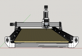
Lead Screw Driven Ox Derivative (850x1500)

Discussion in 'CNC Mills/Routers' started by Giarc, Mar 23, 2016.

  1. attyjay

    attyjay New
    Builder

    Joined:
    Aug 17, 2016
    Messages:
    1
    Likes Received:
    0
    Hi Giarc, great build first of all.

    I'm not understanding your two pictures above which are showing the accuracy; you started at 10mm and sent it 1000mm yet it ended up at 1015mm and that's ok? Maybe i'm reading it wrong.

    EDIT: geez, never mind I was reading your ruler wrong!


    I do have a question about the aluminium pieces, what type of aluminium and what model saw blade did you use? Thank you.
     
    #31 attyjay, Jan 10, 2017
    Last edited: Jan 10, 2017
  2. Giarc

    Giarc OpenBuilds Team
    Staff Member Moderator Builder Resident Builder

    Joined:
    Jan 24, 2015
    Messages:
    3,017
    Likes Received:
    1,682
    I used 6061 aluminum and a Freud 60 tooth 10 inch blade in the table saw. Diablo Tools | 10 in. x 60 Tooth Fine Finish Saw Blade . It was not made for aluminum, but I didn't want to sped $60 for a few cuts. After completing the CNC, I figured all aluminum cuts would be done with it, so no further need for the blade. That being said, it had no problems cutting the aluminum with the blade I had. I used my Rigid miter saw for the extrusion and I believe that was also a 10 inch 60 tooth blade that came with the saw. Wear safety glasses. ;) After cutting a plate, I would sand the edges with my disk sander. I would always leave a little and sand the edge to the line on the template. The aluminum would get super hot when sanding, so I would toss it in the deep freeze that was conveniently located nearby to cool it down faster. I am not a patient man. :rolleyes:
     
    GrayUK likes this.
  3. treoer

    treoer New
    Builder

    Joined:
    Dec 29, 2014
    Messages:
    25
    Likes Received:
    0
    Thank you for sharing your ideas
    I have learn so much from your build.

    I have a question. How do you connect the power to your driver. does the power goes from power adapter (12-24v) direct to the dc + & - or does it go to arduino first then to the driver?
     
  4. Giarc

    Giarc OpenBuilds Team
    Staff Member Moderator Builder Resident Builder

    Joined:
    Jan 24, 2015
    Messages:
    3,017
    Likes Received:
    1,682
    The power goes directly to the drivers (+ and -) from my 36 V power supply. I use a computer to control everything while it is cutting so the only power the Arduino sees is from the USB cable.

    The drivers are wired in parallel.
    powerin.JPG
     
  5. Giarc

    Giarc OpenBuilds Team
    Staff Member Moderator Builder Resident Builder

    Joined:
    Jan 24, 2015
    Messages:
    3,017
    Likes Received:
    1,682
    I found a positive to working in a freezing cold garage today. Neither my beer nor my stepper motors got warm.

    I recently built the new bench my CNC sits on and I wanted to put doors on it to keep the tools and other things stored below relatively dust free. My electronics housing will also be mounted down below. A more detailed description of the bench build along with links to the products purchased for it is in the build section. Here is one end of it and the doors drawn up in Sketchucam. Also, a quick video of a door being cut. I should have cut this at about 4000 mm/min, but I forgot to change the setting before generating the gcode. The others were cut at the 4000 mm/min rate with a shorter single flute cheap Chinese endmill (from a $14 / 10-pack) and I really liked the results.
    doors.jpg


    DSC_0023.JPG

    I was also cutting out a bunch of components from 9/16" plywood. I didn't feel like cutting the 8 foot sheet down because I am lazy. So, I just cut-- fed more in--cut-- and repeated until material was consumed.
    20170116_190900.jpg

    I have to say I really love Sketchucam for cranking out quick 2.5D drawings and Gcode. The project this was for did not really need a specific thickness, I started with 1/2 inch plywood scraps and quickly ran out. I found this 8' piece of 9/16" I have had taking up space in my garage for years and just changed the Sketchucam settings from 12.7 mm material thickness to 14.4 mm and the cut depth from 6.35 mm with two passes to 4.8 mm with three passes. Then created new Gcode. Easy peasy.

    I did get lucky today. I guessed right, but barely. Luckily I didn't switch to the 1/4" endmill:
    DSC_0025.JPG
     
    #35 Giarc, Jan 17, 2017
    Last edited: Jan 17, 2017
    Joe Santarsiero likes this.
  6. treoer

    treoer New
    Builder

    Joined:
    Dec 29, 2014
    Messages:
    25
    Likes Received:
    0
    Thanks for the reply! Does the voltage affect the amp calculation? let sat 12v 24v and 36v. each motor need 2.8A x 4 = 12A + 2 = 14Amp is there benifit using 36v over 12v since the motor are only rated 3v?

    Also why did you choose the screw shield instead of pluging the exturnal drivers to the cnc shield?
     
  7. Giarc

    Giarc OpenBuilds Team
    Staff Member Moderator Builder Resident Builder

    Joined:
    Jan 24, 2015
    Messages:
    3,017
    Likes Received:
    1,682
    Steppers like higher voltage. My steppers are rated for 12-48 V. I have never seen a 3V stepper. The steppers sold at the Openbuilds part store are rated 12-48V. My power supply is 36V and 11 amps. 2.8 amps is the maximum the steppers will draw. They would all have to do it at the same time to exceed the capacity of the power supply. This will most likely never happen. Here is a great guide for understanding steppers and choosing a power supply. Section 6 in particular. It explains this way better than I can. Support | GeckoDrive

    I chose the screw shield because it provided more space to work with, it allowed me to attach additional screw points to make adding capacitors easier for the limit switches, and made everything else much easier to wire up than trying to wire everything directly to the Arduino board. I am using DQ542MA drivers not the smaller drivers like the DRV8825s which are plugged into a CNC shield. I had used those for awhile, but even with heat sinks on and a fan blowing on them they would heat up. I was never comfortable walking away from it with those drivers. Once my fan quit blowing and the Z overheated causing missed steps and a ruined piece of wood. I will save those for a much lighter laser engraver or 3D printer with smaller motors. Also, plugging the external drivers to the CNC shield is much more complicated (to me) since the inputs where the driver chips go are not really clearly labeled.
     
    #37 Giarc, Jan 17, 2017
    Last edited: Jan 18, 2017
  8. Suddensam

    Suddensam New
    Builder

    Joined:
    Jun 3, 2016
    Messages:
    4
    Likes Received:
    2
    I really like your idea of using the micro ATX case to house your electronics. I picked one up and am in the process of figuring out how I want to mount the power supplies and other components for my build. Any chance you could post some pictures of the internals of your setup?
     
    Giarc likes this.
  9. Darathy

    Darathy New
    Builder

    Joined:
    Jul 12, 2016
    Messages:
    74
    Likes Received:
    21
    Same here ,was thinking where i'm gona get a box cheaply so i can put all my electronics in and found some Electrical cabinets which cost 100€ and the cheapest ATX case is 20€(sorry i'm from europe)
     
  10. Giarc

    Giarc OpenBuilds Team
    Staff Member Moderator Builder Resident Builder

    Joined:
    Jan 24, 2015
    Messages:
    3,017
    Likes Received:
    1,682
    I also went with the micro ATX case due to it being way cheaper than electrical boxes. I will take pictures when I am back home.
     
  11. DazTheGas

    DazTheGas Journeyman
    Builder

    Joined:
    Jan 27, 2015
    Messages:
    75
    Likes Received:
    142
    Yep cant beat it, everything of mine is housed in case and still have plenty of room left.

    DazThGas
     
    Giarc likes this.
  12. treoer

    treoer New
    Builder

    Joined:
    Dec 29, 2014
    Messages:
    25
    Likes Received:
    0
    I had a search, I think the other thing would be a network cabinet, Price start about £45 around 2 atx case cost but does come with Strong glass front door which look kind of cool.
     
  13. treoer

    treoer New
    Builder

    Joined:
    Dec 29, 2014
    Messages:
    25
    Likes Received:
    0
    Thank you for the great info, I will look up that link.
     
  14. Rodm

    Rodm Well-Known
    Builder

    Joined:
    Jan 3, 2017
    Messages:
    121
    Likes Received:
    42
    :ROFL::ROFL:
    Is that where your but..I mean clamp was?:ROFL:
     
  15. Giarc

    Giarc OpenBuilds Team
    Staff Member Moderator Builder Resident Builder

    Joined:
    Jan 24, 2015
    Messages:
    3,017
    Likes Received:
    1,682
    Could be. ;)
     
  16. Giarc

    Giarc OpenBuilds Team
    Staff Member Moderator Builder Resident Builder

    Joined:
    Jan 24, 2015
    Messages:
    3,017
    Likes Received:
    1,682
    I did take a few pictures when I built it. I mounted the drivers to more accessible removable side. I drilled holes in a 2 mm thick aluminum plate I cut for the back for mounting the aircraft plugs to connect the motors, etc...
    DSC_0019.JPG


    I did some "computer hacking" (Ha Ha) with a tin snip and made the fan hole bigger and lined it up better. I thought it was odd they did not line up. :rolleyes:
    DSC_0022.JPG

    And with the stepper shield (in the process of wiring it up). DSC_0132.JPG

    [​IMG]

    I mounted the power supply on the opposite side/corner of where the drivers are. It is 36 V and I had some 12 V fans, so I mounted one on the side I showed where the fan hole was modified, one on the back where a fan normally goes, and one exhausting air out the front utilizing the existing fan mount there underneath where the hard drives would be mounted. I did not need three, but 3 in series plugged into the 36 V power supply prevented me from having to add a 12 V power supply, or other electronics. :thumbsup: The Arduino is mounted on the shelf where a DVD or other drive would be mounted. I used the USB port as an input from the computer to the Arduino. I spliced on the end of a USB cable on the inside where it would normally connect to a motherboard. A Google search gave me the proper wire color code for splicing. I use a headphone jack as the input port for my Z-probe. Currently the emergency off is mounted on the outside of the ATX case, but I plan to move it to the outside of the base cabinet soon.
     
    #46 Giarc, Jan 19, 2017
    Last edited: Feb 26, 2017
    Joe Santarsiero and Rodm like this.
  17. Suddensam

    Suddensam New
    Builder

    Joined:
    Jun 3, 2016
    Messages:
    4
    Likes Received:
    2
    Thanks for adding the pictures and detail. Definitely gives me some ideas. I guess for $19 you can't complain to much if the vent holes don't line up.
     
    Giarc likes this.
  18. treoer

    treoer New
    Builder

    Joined:
    Dec 29, 2014
    Messages:
    25
    Likes Received:
    0
    Finally I started wiring my build, I have done the electronic just like yours with screw shield and drivers. I have done all the soldering and about to link up the wires, can you tell me what is the different between drawing the 5v from the 5v pin comparing with En Pin?? I would have thought, connecting Pul(-ve) to Step Pulse, DIR(-ve) to Direction, ENBL(-ve) to Stepper enable/disable and all 3 +ve to 5v pin.
     
  19. Giarc

    Giarc OpenBuilds Team
    Staff Member Moderator Builder Resident Builder

    Joined:
    Jan 24, 2015
    Messages:
    3,017
    Likes Received:
    1,682
    *Edited See this: UNO GRBL DQ542MA Wiring Methods
    Full disclosure: I am not an electronics genius by any means. I have just enough knowledge to accurately mimic people smarter than me to make things work. If it works, I stick with it. :)

    There are two ways of doing it. I chose the method where I would not have to change GRBL settings. See this post in this thread:
    C-Beam cnc

    One thing I found when doing the Z-probe was if I used the ground on the "Digital" side of the board, it didn't work. Duh! It's analog. :banghead:
     
    #49 Giarc, Feb 25, 2017
    Last edited: Mar 2, 2017
  20. Giarc

    Giarc OpenBuilds Team
    Staff Member Moderator Builder Resident Builder

    Joined:
    Jan 24, 2015
    Messages:
    3,017
    Likes Received:
    1,682
    From Kyo's build, it looks like you can use the 5V and this is how I did mine: [​IMG]

    I just followed the GRBL pinouts above and it worked.
     
    #50 Giarc, Feb 25, 2017
    Last edited: Feb 25, 2017
  21. treoer

    treoer New
    Builder

    Joined:
    Dec 29, 2014
    Messages:
    25
    Likes Received:
    0
    I tried your way but didnt work but i need to do more learning on the grbl settings. I am using grbl controller which the setting table doesn't work its only work by typing by hand so i have not play with it much yet. I think i will try gcode sender, that seem to work for others.

    Kyo way I have seen on youtube but some say the enable pin has to be in also or reduced motor torque will happen.

    Its getting exciting, cant wait to have my machine running.

    Thanks for the helpful information.
     
  22. Giarc

    Giarc OpenBuilds Team
    Staff Member Moderator Builder Resident Builder

    Joined:
    Jan 24, 2015
    Messages:
    3,017
    Likes Received:
    1,682
    I use GRBL Panel. It works well for me.
    You had me second guessing myself, so I looked closely at my picture above and noticed no wire in the "Enable" spot on the shield.I remember having an issue with the drivers not working when I first hooked it up. Just now I went out and looked and noticed I did switch to the 5V like Kyo's picture which is why the enable spot on the screw shield is empty. I really apologize for leading you down the wrong path. I thought I had edited my build to reflect the change. I will edit the above post to correct it. Go with Kyo's drawing, it works.

    My updated wiring diagram:
    [​IMG]
     
    #52 Giarc, Feb 25, 2017
    Last edited: Feb 25, 2017
  23. treoer

    treoer New
    Builder

    Joined:
    Dec 29, 2014
    Messages:
    25
    Likes Received:
    0
    It make sense now haha. Its ok, its hard enough to build this machine, it even harder to document everything while doing it. Do you mind share you grbl settings as well that will be really helpful?

    Thank you
     
  24. treoer

    treoer New
    Builder

    Joined:
    Dec 29, 2014
    Messages:
    25
    Likes Received:
    0
    Are you sure you are wrong?? I can still see the red wire on pin 8 en to the yellow wire from the picture above.
     
  25. Giarc

    Giarc OpenBuilds Team
    Staff Member Moderator Builder Resident Builder

    Joined:
    Jan 24, 2015
    Messages:
    3,017
    Likes Received:
    1,682
    DSC_0135blown.JPG If you look close, pin D8 has En written on it in sharpie. It is actually the 9th pin because on the digital side, the Arduino starts with pin 0 (RX0). Pin 1 is TX0. There is an empty screw terminal between the yellow and red wire.

    *edited 2/26/2017
     
    #55 Giarc, Feb 25, 2017
    Last edited: Feb 26, 2017
  26. treoer

    treoer New
    Builder

    Joined:
    Dec 29, 2014
    Messages:
    25
    Likes Received:
    0
    What I mean is the other digital pin 8 on top, where you solder on the under side to the extra screw to the yellow cable. If this image is updated, then you are connected to EN instead of 5v. I test on mulit meter the en does produce about 4.2v but the 5v produce 4.7v. I think your does work but need the right GRBL settings which I haven't setup. As long as I can swap around the cables and settings without burning anything, I am ok.

    DSC_0135blown.JPG
     
  27. treoer

    treoer New
    Builder

    Joined:
    Dec 29, 2014
    Messages:
    25
    Likes Received:
    0
    I have tried the 5v and GRBL Panel and it is working now. GRBL Controller would not work because it need to be home first , and my limiter is not installed yet. GRBL Panel look much more powerful. Thanks

    Update:
    I have done few more tests, I will do it like Kyo Second way, Connect step dir and en to (+ve) and neg to Ground including the en (-ve) instead of leaving it empty. $4 setting stay as 0 does not need to change. I am not sure is it because he is running on Raspberry Pi instead of Arduino?? When I change $4=1 it stopped working. I have also tried without the EN(-ve) but the motor idle noise acting funny on and off. When I connect the EN(-ve) its totally silence at idle. However I have only connect with one motor so far.

    More update:

    I have taken the EN(-ve) out from the driver as Kyo suggested and switch $4=1 when En(-ve) is connect it turn the fan of my power supply off, so it can't be right.
     
    #57 treoer, Feb 26, 2017
    Last edited: Feb 27, 2017
  28. Giarc

    Giarc OpenBuilds Team
    Staff Member Moderator Builder Resident Builder

    Joined:
    Jan 24, 2015
    Messages:
    3,017
    Likes Received:
    1,682
    That wire has been removed. I did not catch that in the photo. These are old photos from prior to finalization and putting it into the box. I will try digitally editing it because it would be a pain to unscrew and remove it from the control box. Thanks for catching that.

    **pictures have been corrected in this thread and in the build.
     
    #58 Giarc, Feb 26, 2017
    Last edited: Feb 26, 2017
  29. Kyo

    Kyo Veteran
    Staff Member Builder Resident Builder

    Joined:
    Feb 27, 2014
    Messages:
    673
    Likes Received:
    702
    Apologize for the slow response. I wanted to put together a bench test unit to go over all the variables as I last tested this with grbl 0.9 and we are now on grbl 1.1

    DQ542MA_Bench_Test_Unit.jpg


    The only sound you should hear is the low hum of the steppers being energized ( this is normal ) . As you have it wired, while you will get movement from the stepper with a $4=0 setting the driver will be going in and out of fault mode. ( led will flash between red and green ) It stops working with a $4=1 setting as you have a gnd connection to the enable - terminal. As per the driver data sheet this pin must be left disconnected. Connecting this to ground disables the driver.

    grbl setting $4 should be changed to $4=1 for proper function of the dq542ma drivers when using the arduino / grbl enable pin ( other drivers may differ ) and the enbl - terminal left disconnected. The driver wants to see a +5v signal to enable and 0v signal to disable this is the opposite of what grbl does by default. The default settings is $4=0 and provides a +5V disable signal.

    I would be happy to do a updated video using grbl V1.1 and just a uno as shown in my above bench test image if it would be more helpful ( no Raspberry pi , nano combo like before )..
     
  30. Giarc

    Giarc OpenBuilds Team
    Staff Member Moderator Builder Resident Builder

    Joined:
    Jan 24, 2015
    Messages:
    3,017
    Likes Received:
    1,682
    I have mine working, but a better explanation for others may help. I may have confused people due to some photos I took while wiring mine and then changing things and not correcting the photos. I have since corrected them.
     
    Kyo likes this.

Share This Page

  1. This site uses cookies to help personalise content, tailor your experience and to keep you logged in if you register.
    By continuing to use this site, you are consenting to our use of cookies.
    Dismiss Notice