Welcome to Our Community

Some features disabled for guests. Register Today.

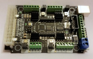
CNC xPRO Driver

Discussion in 'Other Builds' started by Spark Concepts, May 25, 2014.

  1. Serge E.

    Serge E. Journeyman
    Builder

    Joined:
    May 6, 2014
    Messages:
    730
    Likes Received:
    252
    I am running into an issue with the Z axis with both a v1 and a v2 CNC xPro.

    Latest details are at myOX : a 4' x 2' OX with potential as I don't want to duplicate the thread, I'll keep it short here. Someone must be able to figure out what is going on with myOX.

    As brief as I can make the last few weeks (details over at my build, see above link):
    • several weeks ago myOX, which has 4 NEMA23 and a CNC xPro v1, started acting strange : the Z axis stepper would bind 'randomly' for parts of some full retracts, a travel length of 3/4" + 1/8". Shorter moves were fine 100% of the time.
    • Many tests confirmed travels of more than 3/4" would most often bind and release, anything else seemed fine 95 % of time
    • leadscrew of Z as rest of assembly seems fine, block seems fine, ... everything looks as good as it was before the problem started, which is the puzzling thing. I had worked hours surfacing an oak slab just prior to the issue with Z.
    • nonetheless, I replaced the wiring to Z (and X - by accident). Solder joints were in track and not the greatest. Heavier gage, better solder and ... the issue with Z axis remained
    • then I replaced the stepper motor, issue remains ... but now does the bind and release passing 1.5" travel length (!?!)
    • replaced the controller with a CNC xPro v2 - bind/release is gone; however, Z stepper now freezes and requires me to shut power supply off while keeping the USB power to controller on to bring this stepper back to life. X and Y work fine 100% of time (before, during and after Z stepper issues).
    • swapped the connections of Z and X stepper, at board level (easiest), and all steppers are working fine (!) But Z thinks it's X and vice versa (no changes to GRBL settings, so travel distance is obviously off).
    • swapped v2 back to v1 board, returning to the original setup, and the bind/release of Z is back ... apparently at 1.25" travel and beyond (in single commands).
    What is going on ??? I'm obviously missing something, but what ??????

    It can't be interference since both cable runs for Z and X run parallel to each other and are made using same cable type (same spools in fact). X works fantastic, but Z is messing up if wired to Z driver.

    It doesn't seem to be the v2 board, although Z stepper behaves only when connect to X driver.

    If someone can enlighten me, it would be greatly appreciated.
     
  2. snokid

    snokid Journeyman
    Builder

    Joined:
    Oct 11, 2014
    Messages:
    335
    Likes Received:
    104
    serge did you check the current going to the z stepper?

    Bob
     
  3. Serge E.

    Serge E. Journeyman
    Builder

    Joined:
    May 6, 2014
    Messages:
    730
    Likes Received:
    252
    Yap. I think I went through just about everything... played with the step timing (from 10 usec to 25), etc. The only thing I don't remember trying is the old stepper with the new controller. But I think I did that connecting the stepper direct to the controller, before changing the wiring ... I feel like a dog chasing his tail. :oops:

    On the old controller it was working fine for at least a year before it started acting up. On the 'new' v2 controller I set all four to about the same level (visually) and for Z even tried various other settings (basically up from the 2/3rd setting to full). No diff, at least none I could notice doing the short 1/8" to 2.5" moves up and down. Mostly 3/4" to 1.5" given that's where issue with 'v1' surfaces. Even made sure to power everything down, including controller itself, when changing the pot setting ... just in case.

    Why would everything work when I wire the Z stepper to the X driver and the X stepper to the Z driver ?

    With the new controller, I played with the maximum rate and accelaration of all axis. I have X (and Y) flying on rapids with not single missed step over 40" travel in the case of the X axis ! But Z could care less (not enough distance to really hit/see those peaks ?) and either binds/releases with the v1 (mostly on moves of a certain length) or goes into a deep coma with the v2 with moves of any length (usually after only a few moves).

    I just don't get it. I'm obviously missing something. It might be the provervial 'missed comma' (referring to programming days). Once fixed it will be so obvious I'll be kicking myself in the ... I kind of hope !

    In the meantime, I just don't get it ... I've been puzzling over this for ... nearly 2 months now. :oops: I had many suggestions over myOX build's thread. But nothing seems to make my Z behave normally.

    I need to restart all testing and permutations, writing down all steps taken and results seen ... being as zen as I can through the entire process. Take the black box approach and see what inputs give what outputs and try to make sense of it.

    It may be as simple as my soldering skills. Although the other 3 steppers have no issue and everything worked for over 1 year. Note I even rewired the X axis with exact same wire from same spools (mostly because I cut the wrong wires). It works just as fine now as before ...

    Over the coming weekend I'll finish assembling the smaller C-Beam, from which I borrowed the v2. Maybe the solution / cause will become obvious through that exercise ?

    As we say back home, it might be one of those things which depends on the flexibility of the cow's tail and the speed of wind ! Totally unrelated parameters, but why not at this stage ...

    To distract me a bit, although the cogs are spinning full speed in my little head, I am practicing with SketchUp and the many 3D parts in OpenBuilds library over at the SketchUp warehouse for a brand new design / concept also trotting in the vast openness of my mind. But why bother if I can't even get my one Z axis to behave properly with 2 controllers and 2 steppers in hand ? :oops:
     
  4. snokid

    snokid Journeyman
    Builder

    Joined:
    Oct 11, 2014
    Messages:
    335
    Likes Received:
    104
    mmmm this is a tuff one for sure...
    with the motor off how does the lead screw turn?
    I remember your first photo's of your build but don't remember how you have the wires run. with the z going up and down maybe a wire broke or is about to break on the stepper.
    did you try a different g-code sender?
    maybe if I throw enough things against the wall maybe something will stick!!!
    Bob
     
  5. Serge E.

    Serge E. Journeyman
    Builder

    Joined:
    May 6, 2014
    Messages:
    730
    Likes Received:
    252
    Power off, I can turn the shaft of stepper with no apparent issues. Both of previous stepper and of the brand new identical stepper. At first I was pretty sure it was the stepper at fault, so I ordered its twin from StepperOnLine.

    I always add a piece of shrink tubing at cable coming out of the steppers, stuffing it a bit in (without forcing), to reduce stress. Then wires are relatively loose from there to the splice just inside the chain guide. There is a split flexible tubing to keep wires nicely bundled and free to move as Z moves up and down.

    I had tried a different version of the UGCS. Only Z is affected, and only when connected to the Z driver ... I doubt it would be software, especially when it worked fine until recently. Tests done using the 'machine control' (manual controls) as well as two jobs which ran fine before all of this started.

    That's what I'm hoping for. Please, anyone, throw any ideas my way. In time we should be able to find what sticks to the wall.

    This one has me into a loop which is testing my patience ...
     
  6. snokid

    snokid Journeyman
    Builder

    Joined:
    Oct 11, 2014
    Messages:
    335
    Likes Received:
    104
    what size stepper do you have on the z?
    I mean take the motor off and turn the lead screw by hand might feel something....
    Bob
     
  7. Rob702Martinez

    Builder

    Joined:
    Aug 20, 2016
    Messages:
    19
    Likes Received:
    1
    Hi, Need help with V3 controller. Having a hell of a time with this thing, bought it on the BF special. Also about 4 months new to CNC.
    This is my hardware and software stack. Also followed the video word for word, in the video,

    C Beam Mechanical bundle w/ 23 motors-
    Xpro V3- 24v supply
    Grbl Panel

    Fusion 360 for CAD/CAM/SIM, post process as a .NC file.

    Problem......

    I can open Grbl Panel, connect to the controller, and jog the machine around, set it to zero zero. All good.
    I can load an example gcode such as the "hello world" drawing, and it will run the course as it should.

    I can not see any grbl settings in grbl panel and in the settings tab the GRBL version Misc. info section is all grayed out.

    When I have a file from Fusion360, post processed, say a simple circle to cut out of 3mm stock, about 2inx2in, simulates perfect, WCS/ORGIN ZERO ZERO etc.. all that is correct to the best of my knowledge.
    Starting in the lower left corner as 000/000, press play, machine jogs all the way to top left until it jams.

    I have tried Xloader to load Grbl .hex files to the controller, and that also does not work.

    Been google searching for weeks and to the best of my knowledge this is the best I can describe the problem.

    To be extra specific, go to the Cbeam build video

    go to timeline
    1:14:00 thru 1:16:00 of the video, this setting tab is blank and when I press "get grbl settings" nothing happens.

    Thanks for your help in advance.
     
    #607 Rob702Martinez, Feb 4, 2017
    Last edited: Feb 4, 2017
  8. Spark Concepts

    Spark Concepts Journeyman
    Builder

    Joined:
    Dec 17, 2013
    Messages:
    131
    Likes Received:
    107
    Sorry folks - seems I missed some activity this week!

    @Rob: GRBL 1.1 is still in BETA but we are starting to work with it now. There shouldn't be a significant change with GRBL 1.1 in the way of pinouts, however some of the interface was changed so some of the sender will not work properly. Looks like the most compatible at the moment is GRBL Panel. We will update soon with what we find!

    @ImagClaw: There have been a few laser builds, most seem to use the JtechPhotonics equipment (no endorsement intedended as I haven't used the hardware myself). They do have a pretty good write up though - https://jtechphotonics.com/?page_id=4697
     
    ImagClaw likes this.
  9. Spark Concepts

    Spark Concepts Journeyman
    Builder

    Joined:
    Dec 17, 2013
    Messages:
    131
    Likes Received:
    107
    @Serge E.: I felt like you deserved your own post :blackeye:. To be honest this one is perplexing, so I'm gonna throw out some thoughts and ask a few question and hopefully we can sort things out quickly.

    My first thought would be a possible mechanical interference, maybe cutting debris on the screw? Second would be wire fatigue. Third would be federate, acceleration, and current setting. Fourth would be the motor driver IC giving up on life. However, you have covered most of these.. o_O

    So, on to the question and random bits of information part:

    Does it happen at roughly the same height with the same motor? Can you jog the Z axis past this point or repeat the movements that fail? If you remove the flex coupler on the Z motor and run the test program, how does the motor respond, still fail?

    You mentioned the V2 driver going into a "deep comma" - the motor driver ICs have built in protection for overcurrent, undervoltage, and over heating. Of these the overcurrent require the motor power supply be removed to restart the driver. For undervoltage, once the drive voltage reaches ~8.2V again the driver will start up. Similarly with the overheating - once cooled the chips start again. Hopefully helpful information.

    What are you using to power the board?

    Lastly, could you post a screenshot of your settings (or email them to me)?

    Thanks,
    Mike
     
  10. Spark Concepts

    Spark Concepts Journeyman
    Builder

    Joined:
    Dec 17, 2013
    Messages:
    131
    Likes Received:
    107
    @Rob702Martinez: With the hello world program running as it should I would suspect that your work coordinate system and your tool orientation are misaligned in Fushion360 - I recently got to play with a PocketNC (little 5 axis mill) and had a heck of a time getting this squared out in my brain :banghead:... If you could send me your Fushion360 file along with your current machine setting I will look over them for you (please send to [email protected]).

    I'm not to familiar with GRBL Panel (I know... its on the list trust me) but will look into why your setting are grayed out as well. In the meantime, to get your machine settings you can use Universal Gcode Sender (free on GitHub) and send command "$$" to the board and it will spit out a list of you settings.

    Please let me know if you have any questions (build discussion, OB mail, or email (fastest response) all work)
     
  11. Rob702Martinez

    Builder

    Joined:
    Aug 20, 2016
    Messages:
    19
    Likes Received:
    1
    Mike, none of this helped. All my settings are to the book triple checked and now with UGS its worse.
    Don't have much time to spend working out these issues.
     
    #611 Rob702Martinez, Feb 7, 2017
    Last edited: Feb 7, 2017
  12. Spark Concepts

    Spark Concepts Journeyman
    Builder

    Joined:
    Dec 17, 2013
    Messages:
    131
    Likes Received:
    107
    Hi Rob, I get the frustration - there is a decent size learning curve especially when compared to something like a 3d printer. Unfortunately, there is no magic print button for CNCs (hopefully someday). If you cam and orientations are not correct things will go terribly wrong no matter what you use. If you would like any more help troubleshooting let me know - we will be here
     
    Mark Carew likes this.
  13. Mark Carew

    Mark Carew OpenBuilds Team
    Staff Member Moderator Builder Resident Builder

    Joined:
    Jun 28, 2013
    Messages:
    2,758
    Likes Received:
    2,441
    @Rob702Martinez please also check that your in the right units (in/mm) when exporting the gcodes
     
    Spark Concepts likes this.
  14. ImagClaw

    ImagClaw New
    Builder

    Joined:
    Oct 20, 2016
    Messages:
    5
    Likes Received:
    0
    Excellent! Thanks for the info, it's quite helpful!
     
  15. Serge E.

    Serge E. Journeyman
    Builder

    Joined:
    May 6, 2014
    Messages:
    730
    Likes Received:
    252
    It's a NEMA23, single shaft version of the other 3 steppers.

    Tried the stepper off the machine and checked the lead screw, spins fine on its own. Even turned it around just in case, no change in situation.

    The steppers, tried two identical steppers, act up even when not in the machine and connected direct to both controllers ... Strangest part is that both steppers bind/unbind on one controller and freeze on the other.

    Connecting the X stepper to either controller Z driver gives the same results.

    I'll be starting all tests over from scratch.

    Right now I'm putting together a smaller machine, using NEMA17. I will test both controllers on that new machine.
     
  16. Serge E.

    Serge E. Journeyman
    Builder

    Joined:
    May 6, 2014
    Messages:
    730
    Likes Received:
    252
    I sure hope so ...

    Several times ... brain is getting numb at this end.

    With the V1 controller and the original stepper (going from memory) it was doing the bind/unblind on single moves of about 3/4". Jogging with anything less over full travel length had no issues. This was using the machine control tab of UGS. Sending a file, look ahead seemed to come into play if several moves send for same direction of travel. With the V2 controller it just froze when ever it felt like it. The behaviour remained if the stepper was taken off machine and connected to either controllers. Same with a second (brand spanking new) stepper (identical model).

    The puzzle here is that it affects only the Z stepper. I will have to retest with the X stepper connected to the Z driver, and Z to X. Also, instead of pulling the plug and shutting everything down, I could get things going even if the controller (either one) was left powered to the USB. Of course, main power being off, the overvoltage and overcurrent might be able to clear (?)

    I need to redo all of the tests, taking precise notes ... Having changed the stepper, the controller and the wiring (swapping a few times through most if not all permutations) I was really scratching my head on this one for two long.

    Same 24V power supply used through out the previous year (+) when all seemed to work just fine.

    At all times, the wiring for both X and Z steppers was identical - whether the original (which worked for 1+ year), the flat LED cable (probably too small AWG) and the 18 AWG currently (probably a tad too big, difficult on controller side). Both go through same path, slight variation at board and steppers (different connection points, but real close).

    Certainly, but I tried so many variations of that as well, I'll have to reconnect the boards and grab the settings from both. Let me see if I have the original V1 settings (screen capture) ... these would be the ones used through out the year with no issues. The V2 settings are for GRBL .9 and ones I played most with since it only had the freeze issue.

    I'll have to reconnect to the V2 controller. But V1 is attached.

    Pot settings on the controllers for all drivers are at about 3/4 mark.

    The NEMA23 for X and Y are StepperOnline 23HS30-3006D while the two Z steppers tried are 23HS30-2804S. The pages at supplied links have all the specs on these, in case it helps.

    Thanks, in advance, for any and all help on my situation.

    I'll retest tomorrow as I also finish (I hope) an other build (a plain C-beam) which had been sitting idle for too long ...

    In the last week or so, I went to a scroll saw (!) to do a few 2D jobs. I long for myOX and the C-beam to come to life ...
     

    Attached Files:

  17. Spark Concepts

    Spark Concepts Journeyman
    Builder

    Joined:
    Dec 17, 2013
    Messages:
    131
    Likes Received:
    107
    This breaks my heart Serge... Also, I haven't seen that firmware in years!!

    Thank you for the update information. If you would like to send the boards in, I can have a tech look over them and sort things out - might be quicker and it might save you some hair pulling. If not, I will run through this new info with them Monday morning and get back to you soon.
     
  18. IndyMaker

    IndyMaker New
    Builder

    Joined:
    Jan 4, 2017
    Messages:
    9
    Likes Received:
    37
    I powered up my first build last night and could use some help troubleshooting. The electronics are a typical Ooznest specified build; CNC xPro V3 board powered by a 24V power supply, with 4 Nema 23 steppers. On power up, I'm able to connect to the xPro via USB cable and communicate using Universal G-Code Sender. I configured GRBL with the recommended settings per the Ooznest directions. On the xPro, I've got two solid green LEDs, which appear to indicate power and USB connection.

    After config, I went to the Machine Control tab, however I am unable to get any motor movement. I powered down, checked my wiring by confirming I had the stepper coils matched up. I rewired, powered back up, and still not motor movement.

    I pulled the board off my build and moved it to the bench to make it easier to troubleshoot. I wired a single spare stepper to it and still nothing. The GUI on the computer is showing that it is sending the movement commands, however there is no indication on the board. I can manually spin the stepper shaft with no resistance. When I do, an orange LED on the board lights up from the induced current I assume. Curious if this light is supposed to light up when it is trying to signal the stepper?

    Any advice on further troubleshooting is welcome. Trying to determine if I have a bad board, or if this is a configuration issue?
     
  19. Spark Concepts

    Spark Concepts Journeyman
    Builder

    Joined:
    Dec 17, 2013
    Messages:
    131
    Likes Received:
    107
    @IndyMaker - hopefully I catch you while your on, try flipping your setting for $4. Alternatively, send commands "$RST=$" which will default all settings. Then update your settings but leave $4 as it is defaulted. Let me know if this helps
     
  20. Peter O'Hagan

    Builder

    Joined:
    Jan 2, 2017
    Messages:
    9
    Likes Received:
    3
    Hi. Hope you guys don't mind me dropping into the discussion only I need some help
    I have just completed my first build and want to connect my v3 board. However I am not sure of the steps I need to go through
    I have a cbeam xl but don't know the grbl settings
    I am completely confused about where to place my microswitches and the whole area of homing
    Also the commissioning (initial set up) process.
    Sorry to ask but unfortunately I don't know what to do
    Thanks p
     
  21. IndyMaker

    IndyMaker New
    Builder

    Joined:
    Jan 4, 2017
    Messages:
    9
    Likes Received:
    37
    You are the man! Thanks so much, single stepper is turning. Moving the board back into the machine and rewiring.
     
  22. Serge E.

    Serge E. Journeyman
    Builder

    Joined:
    May 6, 2014
    Messages:
    730
    Likes Received:
    252
    Thanks.

    I'm just finishing the build of the C-Beam - standard configuration. I'll be testing both of the boards (V1 and V2) in the next hour or two. If all is well, I'll need for tear down of myOX and do a clean electrical from scratch. In that process I will probably do a few mechanical mods as well (#1 is stretch my Y axis).

    However, if there is still issues, especially with the Z, then I'll have to think about sending both controllers in for someone at your end to verify. I'll have to check a reasonable shipping option. Not sure if you have an upgrade plan to go to V3 (?) But I would consider adding a V3 on the return trip of my two boards. I would not mind getting the firmware update along the way ... if they prove ok at your end.

    In meantime, if they can review the information and give some feedback on what might be wrong. I'll also redo some tests with myOX and forward notes to you ... might help your tech. But probably do those test on myOX late Monday. Maybe your tech will have a few things for me to tests before then ?

    We'll see after Monday what my next steps are to get myOX (and possibly the C Beam) going, if I can't get anything out of either controllers in the next few hours.

    Fingers crossed.
     
  23. Serge E.

    Serge E. Journeyman
    Builder

    Joined:
    May 6, 2014
    Messages:
    730
    Likes Received:
    252

    Good news, of sorts.

    I have the C-Beam standard configuration running with the V1 CNC xPro. All three axis can travel at least 3" without any bind/unbind or freezing. Ok, I will admit I just wired and powered everything and sent only a few commands, 1st mm to check directions of travel and right away long travels to comfort myself.

    So myOX has something quirky on the Z axis. What, remains to be discovered. This is the bad news. It's not the controllers, which is now more obvious. I did changed the wiring of both Z and X with no improvment on Z nor issues with X. Changed the Z stepper with no improvment either. Changing the controller is changing the behaviour of Z only, but not for the better. Instead of bind/unbind stepper freezes until power supply is cycled off/on. This leaves only the power supply. But why would it affect only Z and only when moved a certain distance (V1) or randomly (V2). I'll redo the tests now that I now it is not the (V1) board. Spare 24v power supply is ... somewhere. So I can switch that has well ...

    I'll try with the V2 board in a little while. I just want to exercise the C-Beam for several minutes just to be certain I'm not prematurely jumping of joy ...

    Things are looking up ... I think.
     
  24. Spark Concepts

    Spark Concepts Journeyman
    Builder

    Joined:
    Dec 17, 2013
    Messages:
    131
    Likes Received:
    107
    @Peter O'Hagan - Welcome! No worries, that's the whole reason we are here. To start, you will need a sender program, I would recommend Universal Gcode Sender as it is fairly straight forward and quick to pickup (can be downloaded on GitHub free).

    Next, you will need to connect your board via USB to your PC, give it a minute for the drivers to load, and open Universal Gcode Sender. In the top left corner, select the com port for the board (should be the only one unless you have other products plugged in), verify that the baud rate is set to 115200, press connect. You should receive a "GRBL 0.9x ..." statement meaning the board is talking.

    Next in the command tab, type "$$" and press enter - the response will be your current GRBL settings. To start off let's keep things simple - ignore most of the settings as the default will be good enough. The ones you need to pay attention to immediately are $100, $101, and $102 as these set the step/mm (or scaling if you will) for the X, Y, and Z axis respectively. For a CbeamXL these should be set to 200 for all three axis as a starting point (some tuning later on should be expected but in the decimal range i.e 200.15, etc). In the command box enter "$100 = 200", press enter, "$101 = 200", press enter, "$102 = 200", press enter. Now you can flip over to the Machine Control tab - in the upper right there are jog controls. Set the movement to something very small - 1mm ish - and jog each axis to confirm it is going in the direction you would like it to. If not, you can set the $3 direction port invert mask - it is an integer set off binary coding of 0ZYX - where a $3=4 (0100) would invert the Z axis OR you can flip the A1 and A2 motor leads on the board for the axis you want flipped. A good time to mention - The <A> motor block is defaulted to clone the Y axis exactly if your motors face in opposite directions (like an Ox) one set of leads on the <A> motor block need to be switched where as if the motor face in the same direction they need to be wire identically - if not bad bad things will happen :blackeye:

    Now at this point you should be able to move in the correct direction and in the correct magnitude. So the last bit is the limit switches and homing - the X, Y, and Z motor connector blocks have inputs and ground for limit switches. You need to wire the switches 'normally open' then put one lead into the ground connector and one into the switch connector for each axis. If you want to run limit on both end of an axis, simply repeat the process for the second switch (wire it in parallel with the first switch). Now you need to set the firmware to look for limit switches by issuing the command "$21=1". Now if you are going to crash the machine will sense the limit and stop motion!

    Next - homing - enable it with the command "$22=1". When homing, the machine should first move in the -Z direction, then in the -X-Y direction until it encounters limit switches. It will then pull off the limit switches and be homed. This means that you need to have limit switches at the negative XYZ ends at a minimum. Also note, with homing enabled you will not be able to move the machine until it is homed.

    ... I thought this was gonna be short and sweet... so uh, clear as mud? Let me know if you have any questions (most answer should be shorter now :thumbsup:)
     
    Mark Carew likes this.
  25. Spark Concepts

    Spark Concepts Journeyman
    Builder

    Joined:
    Dec 17, 2013
    Messages:
    131
    Likes Received:
    107
    @Serge E. good to hear you are making progress - ish! Let me know if you find anything else. If I'm not mistaken - and by the looks of the firmware I am not :eek: - you have been with us since the kickstarter days, yes? We definitely have an upgrade plan ;)
     
  26. Peter O'Hagan

    Builder

    Joined:
    Jan 2, 2017
    Messages:
    9
    Likes Received:
    3
    Many thanks Michael - I will work through that over the next few days (sadly back to the weekly toil today) If Ok with you I will probably get back to you as issues arise and my knowledge tank is empty. BW Peter
     
  27. Serge E.

    Serge E. Journeyman
    Builder

    Joined:
    May 6, 2014
    Messages:
    730
    Likes Received:
    252
    Yes, the V1 board is actually through a KickStarter pledge - one of my very first pledges (now near 50). Just checked, I'm contributor #81. I unfortunately :oops: never bothered doing the firmware updateS as it worked great ... until recently.

    The V2 came with a fully configured C-Beam Plate Maker kit from OpenBuilds Parts Store.

    Do you want to PM me with the upgrade plan. I might upgrade the V1 and, if I can afford it, upgrade the V2 or just get 3rd controller for the C-Beam and keep the V2 for testing designs without having to tear down my 'working' machines. I didn't get around to test the V2 with the C-Beam, but I suspect it will work fine as well. It's something in myOX that is screwy !!

    Which leaves myOX in intensive care ... I might just stick to small jobs the C-Beam can handle while I plan redoing myOX with a bunch of mods, many waiting for a 'good' opportunity. myOX 2.0 in the making ? Especially now that I could do my own plates. Must look at the positive side of all situations, right ? I'll need to think through the mods, make a shopping list, prioritize things and see if the tax return will be enough to cover the rebuild ... Long weekend is coming up, perfect time to work those details out, eh ?

    I need to find a good (local) source for some aluminum. Time to reach out to a few local shops ... maybe they'll have a few bits of scrap they wouldn't mind parting with for me to practice on ?
     
  28. Peter O'Hagan

    Builder

    Joined:
    Jan 2, 2017
    Messages:
    9
    Likes Received:
    3
    Hi Michael - it works!! (well- nearly!!):)
    Everything works fine - just a couple of issues that you my be able to help with (sorry to be a nuisance!)
    1. The motors on the Y axis don't seem to work together - under load A seems to judder! But similar resistance when I spin by hand etc.
    2. I imported a very simple g-code file from easel to UGS - looks fine on the screen in the visualiser but is completely mirrored on the router!

    I have decided that homing looks a little tough at the moment so just going to use switches as hard stops is "$21=1" the control to use for this too?

    Hope everything is good with you

    BW - Peter
     
  29. Serge E.

    Serge E. Journeyman
    Builder

    Joined:
    May 6, 2014
    Messages:
    730
    Likes Received:
    252
    Did a bit more testing using the V2 CNC xPro on myOX.

    First, I changed the wiring to the Z stepper (third time now), but kept the same wiring to the X stepper (was changed earlier) Wiring to the Y steppers remains unchanged from day one (1+ year).

    1) Z driver driving Z stepper

    Driving the Z stepper randomly gives me a "freeze" regardless of travel distance. The only way to get the stepper back into operation is to remove power to the 24 V power supply. To close the Universal Gcode Sender connection and to disconnect the USB cable does not make any difference to the Z stepper status.

    The X stepper works great.

    2) Z driver driving X stepper

    Driving the X stepper with the Z driver DOES randomly "freeze" the stepper. I just need to compensate travel distance for fact that the steps/mm are quite different (and I didn't adjust for the test, just swapped wiring at controller) :

    upload_2017-2-20_12-26-42.png

    The Z stepper works great (being careful with the travel distance : factor of ~ 8x !

    Conclusion ?

    After all the multiple cable changes, using 3 different steppers (original Z, new Z and the original X), this leads me to think something is wrong with the Z driver ON the CNC xPro. Just my luck as I was trying to determine if something was wrong with my V1 CNC xPro controller when my Z started bind and unbind, first with travels of about 3/4" or more and then, after having changed the wiring, 1.5+" !

    Next steps

    So now I will do same tests with the V1 to see if the Z stepper bind/unbind reappears. If it does, the two controllers (!?!) have something wrong with the Z driver ... How lucky can I get. If it suddenly is working fine, then it was my wiring all along ! Possible the initial wiring wend bad at the soldering w/ time; my 2nd wiring was no better with too low a AWG; the 3rd was no good with too high AWG; and this most recent wiring is just the right AWG (and also twisted pair shielded for good measure). But why is the X running fine through the first three types of wiring down the same path for almost same length will be beyond me ... or it is just waiting to sneak up on me ...

    If the V1 still does the bind/unbind, I will have to dig out the old Arduino board and drivers ..... or find myself a new CNC xPro or a controller with swappable drivers. Budget and availability will decide ...

    I will also try both CNC xPro (V1 and V2) on my recent C-Beam stock build, for good measure, before buying a new controller. If they both work on the C-Beam, myOX will have me completely confused !!!

    Wish me luck, looks like a need tons of it at this point.
     
    #629 Serge E., Feb 20, 2017
    Last edited: Feb 20, 2017
  30. Serge E.

    Serge E. Journeyman
    Builder

    Joined:
    May 6, 2014
    Messages:
    730
    Likes Received:
    252
    Well, I'll be a monkey's uncle ...

    Redid the tests on the myOX, this time using the old V1 CNC xPro (with original 0.8c)

    So far, connected only the Z and X steppers to their respective drivers. EVERYTHING works great ! The only changed from before is the new wring for the Z (the twisted pair shielded, but yet to be grounded, cable).

    This says something must of went wrong with the original cable (?!?) and the two attempts to replace the cabling were an abysmal failure on my part (probably the wrong AWG and maybe soldering, mix with being unshielded).

    Unfortunately, it also means there may be something wrong with the Z driver of the 'new' V2 card I have. I will give it a try with the stock C-Beam, being with 12V power supply (instead of the 24V of myOX). I also have the option of using the A driver (with a bit of unsoldering and soldering on the controller) since the C-Beam (standard) doesn't use that 4th driver ...

    I'll bring the chatter back to myOX's discussion thread.
     

Share This Page

  1. This site uses cookies to help personalise content, tailor your experience and to keep you logged in if you register.
    By continuing to use this site, you are consenting to our use of cookies.
    Dismiss Notice