Welcome to Our Community

Some features disabled for guests. Register Today.

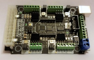
CNC xPRO Driver

Discussion in 'Other Builds' started by Spark Concepts, May 25, 2014.

  1. Spark Concepts

    Spark Concepts Journeyman
    Builder

    Joined:
    Dec 17, 2013
    Messages:
    131
    Likes Received:
    107
    @Serge E. - definitely shoot a PM if you want to discuss the upgrade plan. On the random freezing with the V2, the motor drivers run from the Vm input (in your case 24V) so closing/disconnecting UGS and USB power will not clear any fault state that the driver is in. Looking at your settings the Z acceleration is on the higher end of what we typically use - just for kicks and giggles could you set that around 10 to 50 ($122 = 10)? 150 on the belt drive isn't to bad with 26 steps per mm but 150 on the Z is pretty intense with 200 steps per mm. Let me know if this helps or not (if not I would really like to have a tech look over your V2 to see what is happening with the Z). Please feel free to chatter here as well - it is an interesting issue and useful troubleshooting steps :thumbsup:
     
  2. Serge E.

    Serge E. Journeyman
    Builder

    Joined:
    May 6, 2014
    Messages:
    730
    Likes Received:
    252
    When I used the V1 CNC xPro, which has GRBL 0.8c, I had the $5 (default seek rate - how fast it moves for rapids) set at 3500 mm/min. This controls all three axis (X, Y and, yes, Z). myOX uses GT3 belts for X and Y, thus 26.667 steps/mm, & lead screw for Z, thus 200 steps/mm (all axis set with 8 microsteps).

    3500mm/min at 26.667 steps/mm is approximately 1,555 pulses per seconds (X and Y). The same 3500 mm/min, on Z - which is 200 steps/min, becomes 11,666 pulses per seconds !

    Swapping the wiring between X and Z, withOUT adjusting the steps/mm setting, basically slowed Z and sped up X by ... factor of about 8 (200/26.667). Everything was perfectly happy with this. Z ran much slower than ever and X/Y can do a whole lot faster. I had the X and Y at well over 25,000 mm/min when testing the V2 (GRBL 0.9j, allows individual setting).

    The latest wiring made the 3500 mm/min rapids work fine with all drivers driving their respective steppers ... So previous cabling attempts did have issues ... probably interference, or whatever. The new cable runs for Z and X are twisted pairs with shielding (still not grounded, but the foil is there).

    My Z issue started shortly after I surfaced a thick oak slab. When looking at myOX cut air a few hours ago, it hit me. Bored of seeing the tool go full width into the material, up a hair, rapid back, shift over for the next pass, move Z down just enough to skim the slab and repeat over and over and over, I had played with this $5 setting .... NEVER setting it back after having done the slab ... and thus the issue mysteriously surfaced ! The old cabling could not handle the stream of pulses nor could the other two wiring attempts (very thin LED wiring and 18 AWG unshielded electric wire).

    Mea culpa, mea culpa, mea culpa ...

    Moments ago, as I pushed myOX to 5000 mm/min rapids ($5 - remember, this applies to all three axis regardless of being belt or lead screw driven) brought back the bind/unbind on Z !! The train of pulses must be too much for at least the way I have done the wiring, even with the latest cable. The steppers (X and Y) can take it, and both V1 / V2 CNC xPro can send such streams as it drove the steppers directly wired to it. It leaves my wiring job at cause and my configuring the controller to my wiring's limits.

    This, of course, leaves the issue with the Z driver on my V2 CNC xPro ... it 'freezes' (goes into a full stall). I suspect I have the default (maximum) feed rate (aka rapids ?) set even higher than 5000 mm/min. Since I know I left the X and Y at 25k! This, by the way, at 26.667 steps/mm translates to 11,111 pulses per seconds, which is below the bind/unbind issue (16k).

    So I now run my Z at 10,000 pulses per seconds (3000 mm/min, which unfortunately applies to all axis with GRBL 0.8c) ... with no issues.

    Mystery solved, right ?

    Now I have to think about upgrading the firmware of the V1 and probably V2 ... The V1 could then run myOX faster, add a few features (probing, etc.) while the V2 will do the same to the C-Beam. Both could then see some hardware upgrades...
     
  3. Spark Concepts

    Spark Concepts Journeyman
    Builder

    Joined:
    Dec 17, 2013
    Messages:
    131
    Likes Received:
    107
    @Peter O'Hagan - mostly excellent news! for the juddering A axis - try turning up the current (small potentiometer labeled "current" beside the A drive). For the mirroring - is the part mirrored in X, Y or both? Either one is a simple setting fix ($3 setting) just need to know which axis to flip. Right on with the hard stops, set $21 = 1.
     
  4. Serge E.

    Serge E. Journeyman
    Builder

    Joined:
    May 6, 2014
    Messages:
    730
    Likes Received:
    252
    I'll give that a try probably late tomorrow as I'm curious as well. To be honest, I'm not certain how I got to use 150 for that parameter. I'm somewhat sure I started with close to the default values, but I forget and it is worth a try. If for nothing else, for kicks and giggles. I just need to connect the Z ... and power supply, even if I run full jobs to test it out.

    From what I ... learned today, I apparently have the default feed ('rapids') set high, especially for Z, at least with my wiring. So I will take the opportunity when testing above to also redo tests with a lower value for the Z feed rate / rapids... I would like to figure out the V2 side of my Z situation.

    I suspect, unfortunately, it is my settings at play as well. Especially after getting myOX back into working order with V1 ... Wanting to get back to running jobs on myOX, I forgot to retest the V2 ! Then supper came and I was installing fans back on myOX. I'm telling you this age thing is not working out for me. I can't put down my pen for a second without searching for it minutes later ... sometimes for hours. Well, ok, I just take an other pen and try to figure out why I needed one in the first place. Short term memory certainly is getting shorter ! ;^)

    I wouldn't mind upgrading at least the V1 to a V3. So I'll PM your shortly to see what are the options there.

    A question to all : the V3 also adds "Step/Dir breakout pads". Would this allow for having 2 Z drivers (as in the Big Mouth C-Beam, moving entire gantry up and down) along with 2 Y drivers (as with the OX and C-Beam XL) ? I would use the A driver (on board) to (eventually) drive a 4th axis on myOX 2.0 ...at least to rotate some part to work on different faces, but have possibility to work on cylindrical parts as well. I might need 2 A depending on what I need to rotate... Or possibly go with larger NEMA 34 to get extra torque to move the extra weight ... Just a concept for now.
     
  5. Serge E.

    Serge E. Journeyman
    Builder

    Joined:
    May 6, 2014
    Messages:
    730
    Likes Received:
    252
    Did the test a bit earlier tonight. Sorry for the delay.

    Reconnected the V2 to myOX : just power (24V), the Z driver to Z stepper and the USB. With $122 at 10, Z stepper was 'freezing' within a few moves, even if as short as .5 mm. I tried $122 at 50 with no difference. I didn't try it back at 150... However, during these last few quick tests, I noticed something I didn't look for with earlier tests : the Z stepper was limp! There was no resistance once it 'froze'. I could freely turn it by hand. When power (24V) was removed and restored, the stepper was impossible to turn by hand. I never thought of looking for this earlier.

    I'll try it tomorrow on the C-Beam it came with. I think it ran fine during earlier tests... But it uses a 12V power supply. It could be the Z driver's over voltage protection which is faulty (? can it ?)

    If it doesn't allow the C-Beam to cut air without freezing or other issue, I'll PM you to see how/where you want me to ship the V2 for your techs to see what is wrong ... if anything. I could wait for a verdict to see what the next step would be, I'll temporarely be without a controller for the C-Beam.

    Meanwhile, myOX is running fine with the V1, the max feed rate set at 3000 mm/min. I might be able to boost up a bit ... but why look for trouble ?
     
  6. chrisyln

    chrisyln New
    Builder

    Joined:
    Nov 19, 2016
    Messages:
    1
    Likes Received:
    1
    to invert my Z axis do I just flip A1 A2 and leave B1 B2 as they are
     
  7. Spark Concepts

    Spark Concepts Journeyman
    Builder

    Joined:
    Dec 17, 2013
    Messages:
    131
    Likes Received:
    107
    Yep, or invert the B terminal and leave the As alone. Or use the software settings
     
  8. Christian Knüll

    Builder

    Joined:
    Mar 1, 2014
    Messages:
    27
    Likes Received:
    34
    Hi,

    I hope it is OK to post this here:
    Estlcam is now also able to control machines with the xPro V3 board.
    Just select the "Spark-concepts xPRO V3" preset:

    xpro.png

    It would be interesting for me to get some feedback - I've tested the board alone but not in a machine yet.

    Christian
     
    Serge E. and Mark Carew like this.
  9. Spark Concepts

    Spark Concepts Journeyman
    Builder

    Joined:
    Dec 17, 2013
    Messages:
    131
    Likes Received:
    107
    Hi Christian, this is the perfect place for it! Sorry for the slow response (just got back from a weekend in the woods:D). I fired up the latest version this morning and it programed beautifully. Thanks for working with us on this - going to be a great addition for the users!

    *** quick note for those changing over***
    Check your $4 setting in grbl, if $4=1 make sure you check the "Invert stepper enable signal" before programming the controller in estlcam.
     
  10. anigeek65

    anigeek65 Well-Known
    Builder

    Joined:
    Sep 16, 2014
    Messages:
    57
    Likes Received:
    50
    How about V2 boards?
     
  11. Spark Concepts

    Spark Concepts Journeyman
    Builder

    Joined:
    Dec 17, 2013
    Messages:
    131
    Likes Received:
    107
    We are still testing the V2s. I'll update with more shortly. There are some significant hardware differences between the two that usually are transparent but may come into play here.
     
  12. Mark Carew

    Mark Carew OpenBuilds Team
    Staff Member Moderator Builder Resident Builder

    Joined:
    Jun 28, 2013
    Messages:
    2,758
    Likes Received:
    2,441
    This is really cool guys! :thumbsup: Nice work this is a great addition to an already great software and board.
    Mark
     
  13. Kevin Henning

    Builder

    Joined:
    Mar 18, 2016
    Messages:
    25
    Likes Received:
    2
    Christian, it looks like Estlcam runs on a PC. I am wondering if you were planning on porting it to a Raspberry running Raspbian? I've got a Raspberry Pi 3 that is looking for work :)
     
  14. anigeek65

    anigeek65 Well-Known
    Builder

    Joined:
    Sep 16, 2014
    Messages:
    57
    Likes Received:
    50
    Christian,
    I love EstlCAM, been using for quite a while. Works well where others have failed.
     
    Serge E. likes this.
  15. Spark Concepts

    Spark Concepts Journeyman
    Builder

    Joined:
    Dec 17, 2013
    Messages:
    131
    Likes Received:
    107
    I can't agree more anigeek, I'm very impressed! I'm hoping to run some aluminum parts this weekend for a powerwheels mod. Very excited to test the trochoidal milling on the Cbeam.

    Raspi port would be amazing! I have more than a few waiting for work as well :)
     
  16. anigeek65

    anigeek65 Well-Known
    Builder

    Joined:
    Sep 16, 2014
    Messages:
    57
    Likes Received:
    50
    That sounds cool Michael. I used EstlCAM on my small cbeam machine to make all of my plates to build my large 4ft x 4ft C-BEAM/Ox builds machine. Although I did not use the trochoidal feature for this build. I have played around with it a little but sad to say I have been to busy lately to play with my large toy....

    Alan
     
  17. Christian Knüll

    Builder

    Joined:
    Mar 1, 2014
    Messages:
    27
    Likes Received:
    34
    Hi,

    Raspberry or native Linux support is unfortunately not possible.
    Program development would come to a complete standstill for a year or two just for porting as I'd basically have to rewrite everything more or less from scratch.
    You can however use any old Windows Notebook e.g. from eBay - the controller has very low hardware requirements and will work on any computer running Windows XP or newer.

    Christian
     
  18. Kevin Henning

    Builder

    Joined:
    Mar 18, 2016
    Messages:
    25
    Likes Received:
    2
    Christian, no problem, figured I'd ask. I am looking into purchasing, but I am using the xPRO V2 board.
     
  19. GinoTheCop

    GinoTheCop Journeyman
    Builder

    Joined:
    Jan 28, 2016
    Messages:
    150
    Likes Received:
    196
    Thats such a shame.. Would be great to have all the functionality EstlCam has to offer on my Raspi setup as well..

    Well guess we cant have it all..:D

    Christian, Great software btw..:thumbsup:
     
  20. ChrisV

    ChrisV New
    Builder

    Joined:
    Feb 19, 2014
    Messages:
    10
    Likes Received:
    2
    I've been working my way through a Kyo Sphinx build of the past few months. The mechanical is pretty much finished and I'm working on the electronics. I'm using the Xpro V3 controller with the 24v Openbuilds PSU. I've got the three axis wired and moving. Still working on tuning and settings. But I need some help. I'm trying to figure out how to wire up the limit switches and the z probe. I discovered I really don't know anything about electronics. I tried to test one of the proximity sensors (LJ12A4-Z/BX inductive NPN sensor, blue tip) on the bench. Didn't work well, I literally blew it up, pieces of the tip all over the place. So clearly I don't know what I'm doing. I've searched and watched a number of U-tubes but something is still missing for me. If someone could provide some detail of how to wire the sensors up maybe I can avoid blowing up the rest of them. Thanks....Chrisv
     
  21. Spark Concepts

    Spark Concepts Journeyman
    Builder

    Joined:
    Dec 17, 2013
    Messages:
    131
    Likes Received:
    107
    Christian, quick question - would ESTLcam run on a windows10 tablet?

    ChrisV - ouch, we all let the blue smoke out occasionally though :(. Do you have a link you could post (or pm me) for the units you purchased? There seem to be a few different options on those.
     
  22. ChrisV

    ChrisV New
    Builder

    Joined:
    Feb 19, 2014
    Messages:
    10
    Likes Received:
    2
  23. Spark Concepts

    Spark Concepts Journeyman
    Builder

    Joined:
    Dec 17, 2013
    Messages:
    131
    Likes Received:
    107
    ChrisV, thanks for the link - I'll dig into these a little more and let you know. Nice price on those btw!
     
  24. Spark Concepts

    Spark Concepts Journeyman
    Builder

    Joined:
    Dec 17, 2013
    Messages:
    131
    Likes Received:
    107
    Hi ChrisV, We were able to pull up this bit of wiring information.

    Screenshot_2017-03-10-10-41-44.png

    It looks like you should be wiring should be "Brown -> 12V (or 24V)", "Blue -> GND" and "Black -> limit pin".
    The documentation is a little to be desired :(. I am slightly concerned that when in the switch is in the open state that it will pull the signal to 12V (or 24V). The 5V input is buffered but not really a good thing to do the board long term (and the switch will be open 99% of the time). but the isolator is rated for 20V so applying 24V here will release the magic smoke

    As a quick check - you could wire the Brown and Blue wires as described and then measure the voltage between the blue and black wire when the switch is open to confirm the voltage is not 12V or 24V. If you aren't comfortable with this, I have a unit on order and can let you know more when it arrives.

    Clear as mud?
     
    #654 Spark Concepts, Mar 10, 2017
    Last edited: Mar 10, 2017
  25. ChrisV

    ChrisV New
    Builder

    Joined:
    Feb 19, 2014
    Messages:
    10
    Likes Received:
    2
    Michael, thank so much for the research and the info. I found a you tube by Martin Barford on this but I'm not totally clear on it. It sounds like he's using a resistor to pull down the voltage to about 6v on the signal wire. Here's the link to the video, it will probably make sense to you. . Thanks I'll try to proceed with care before I actually connect to the xpro.
     
  26. Spark Concepts

    Spark Concepts Journeyman
    Builder

    Joined:
    Dec 17, 2013
    Messages:
    131
    Likes Received:
    107
    Hmmm... maybe give me a chance to look into this a little more and see what they are doing. We have pull-ups, buffers, and isolators on the board as well so it isn't a straight input.
     
  27. ChrisV

    ChrisV New
    Builder

    Joined:
    Feb 19, 2014
    Messages:
    10
    Likes Received:
    2
    Michael, Thanks, I'll hold off so as not to break something else.
     
  28. Spark Concepts

    Spark Concepts Journeyman
    Builder

    Joined:
    Dec 17, 2013
    Messages:
    131
    Likes Received:
    107
    ChrisV, it looks like that might be the PNP version of the prox sensor (yellow tipped). This *should* work to suppress any voltage coming out from the NPN prox sensor that is higher than 5.1V. The X and Y axis need to be wired the same way (so 3x resistors, 3x Zeners). Make sure the blue wire goes into the ground terminal and that the band of the Zener faces away from the ground. Please let me know if you have any questions, we will be testing this out when the sensors arrive.

    Inductive Proximity Sensor Wiring (xProV2-V3).jpg
    *DISCLAIMER* - circuit has not been tested yet
     
  29. ChrisV

    ChrisV New
    Builder

    Joined:
    Feb 19, 2014
    Messages:
    10
    Likes Received:
    2
    Thanks Michael, I look forward to learning the results of your testing. In the mean time I'll try to source the zener diode and resistor. We lost our Radio Shack here and seem to live in a electronic desert here in Olympia, WA .
     
  30. Christian Knüll

    Builder

    Joined:
    Mar 1, 2014
    Messages:
    27
    Likes Received:
    34
    Hello,

    yes - Windows 10 tablets should work fine.
    (As long as it is "real" Windows 10 - not one of those crippled mobile Windows 10 "RT" versions)

    Christian
     

Share This Page

  1. This site uses cookies to help personalise content, tailor your experience and to keep you logged in if you register.
    By continuing to use this site, you are consenting to our use of cookies.
    Dismiss Notice