Welcome to Our Community

Some features disabled for guests. Register Today.

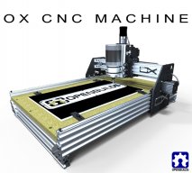
OpenBuilds OX CNC Machine

Discussion in 'CNC Mills/Routers' started by Mark Carew, Dec 15, 2013.

  1. Rharms

    Rharms New
    Builder

    Joined:
    Oct 21, 2014
    Messages:
    3
    Likes Received:
    3
    grbl is cool, but the Arduino is running at its' limits. Make sure your connections are solid and you may try mounting the arduino on foam to eliminate vibrations. Also, I think I saw some wiring that should be looked into. Make sure that wires are separated from each other, and never run parallel. The exception to that are the wires to each motor, they should be twisted together to help reduce cross talk. I believe you are not running limit switches, but if so, make sure those connection are super tight, the smallest movement can make the axis jump, this is especially true on the Z-axis as all of the wires are in constant motion. Good Luck.
     
  2. planga

    planga New
    Builder

    Joined:
    May 10, 2014
    Messages:
    23
    Likes Received:
    3
    I'm finally getting to the stage of wiring up the CNC Pro V2 to my ox. I've installed the board in a box that goes on the back of the gantry. My question is: Is it recommended to add hardwired buttons (start, stop, pause) to the box, or should they be located elsewhere? ...or should buttons be installed at all, are they really necessary or useful since the computer will be controlling the machine? I did figure that I would install a large emergency stop button, but again, where is the best place for that? Any help would be appreciated. Thanks in advance!
     
  3. Spark Concepts

    Spark Concepts Journeyman
    Builder

    Joined:
    Dec 17, 2013
    Messages:
    131
    Likes Received:
    107
    Hi Planga, Depending on the sender you are using the start, stop, pause buttons are probably redundant and not needed. E-stop is definitely recommended, best place to put that is within 1-2 feet of wherever you will be standing most of the time (not on the back of the gantry :blackeye:). For some of the laser builds I like to tell folks to put it by the door they will be running out... people don't seem find that funny though :banghead:. If you have any other questions, let me know.
     
  4. planga

    planga New
    Builder

    Joined:
    May 10, 2014
    Messages:
    23
    Likes Received:
    3
    Perfect, thanks for the answer Michael! That is kind of funny! After I install a laser, maybe I'll just use one of the Halloween switch mats that you step on in front of the door as I run out on fire! ;)
     
  5. Spark Concepts

    Spark Concepts Journeyman
    Builder

    Joined:
    Dec 17, 2013
    Messages:
    131
    Likes Received:
    107
    Switch mat is a great idea - I'm gonna have to find one of these!
     
  6. papergeek

    papergeek New
    Builder

    Joined:
    Dec 13, 2016
    Messages:
    6
    Likes Received:
    0
    Noob question here: I may have access to a CNC router that can be used to cut gantry plates. I've built 3D printers from scratch and need to go this route instead of buying a kit (due to financial limitations; I need to do this one little bit at a time). My question is this: is there a wiki or some description of how to go about cutting your own plates (preferred materials, etc)?
    Thanks!
     
  7. Spark Concepts

    Spark Concepts Journeyman
    Builder

    Joined:
    Dec 17, 2013
    Messages:
    131
    Likes Received:
    107
    JustinTime - a very good plan, and the switches are pretty cheap!

    Papergeek - what time of router do you have access to? A lot will depend on that, but the Shapeoko folks have a really good thread on cutting different materials - admittedly overwhelming but lot of information (Materials - ShapeOko)
     
  8. Rick 2.0

    Rick 2.0 OpenBuilds Team
    Staff Member Moderator Builder Resident Builder

    Joined:
    Dec 20, 2013
    Messages:
    2,892
    Likes Received:
    1,551
    I hope you've got normally open switches... If they are normally closed (push to open) like most E-stops they would need to be in series.
     
  9. papergeek

    papergeek New
    Builder

    Joined:
    Dec 13, 2016
    Messages:
    6
    Likes Received:
    0
    What type of router? Not sure at this point, not sure if I actually have access to one. I may need to look for someone locally (Austin) willing to barter software / firmware / FreeCAD work for cutting. That's a great resource, thanks for the link. It is definitely a lot of info and I suppose I should focus on identifying a person with a CNC router who's willing to work with me, then figure out which of the materials they handle would be best.
    I've heard Garolite mentioned.
     
  10. Stephan Schmidl

    Builder

    Joined:
    Nov 30, 2016
    Messages:
    21
    Likes Received:
    1
    Hi Folks, as I wrote before, I have got an OX with 100 x 150cm. I´m very pleased with it...eccept when it comes to milling results of bows, arcs, circles or curves.
    The OX does not create very smooth edges, circles becom a Little rough, milling machine is some Kind of stuttering a bit, it seems.
    Are there any Settings to Change Resolution ore something, which I can try before investigating the Hardware? I thought, I saw this Topic in the Forum before, but can´t find it.
    Thank you in advance
    Stephan
     
  11. Gary Caruso

    Gary Caruso OpenBuilds Volunteer
    Staff Member Moderator Builder

    Joined:
    May 19, 2016
    Messages:
    1,193
    Likes Received:
    532
    Would need to know what drivers, controller, and software you are using to help, nothing with the machine itself will cause this, unless you are trying to take off (DOC) more than the rigidity of the machine can take. :)
     
  12. Spark Concepts

    Spark Concepts Journeyman
    Builder

    Joined:
    Dec 17, 2013
    Messages:
    131
    Likes Received:
    107
    Should also include your CAD and CAM software. A few of the CAM programs do funny things with arcs and circles...
     
  13. George Smith

    Builder

    Joined:
    Mar 18, 2017
    Messages:
    5
    Likes Received:
    0
    Good Evening,
    I’m hoping the forum can help because I’ve come up against a roadblock.

    Some background on setup:
    - Basic OX design
    - Four NEMA 23 motors with 24V power supply
    - CNC xPro v2 (default 1/8)
    - 22 AWG 4 conductor wire (W122-100-ND from DigiKey)
    - Universal GCode Sender (UGS Platform) on Windows 7
    - gCode generated in Vectric VCarve Desktop (8.5)

    I’ve had everything setup and calibrated each motor running quickly and thought everything was good to go. Over a run of 600mm both x and y were accurate to less than a 0.25mm. Most test shapes I could send worked well. This includes both air cutting and thin (1 mm) cuts into the top of plywood.

    First real project was to create some countersunk pockets for some threaded inserts to hold projects down. I set everything up in VCarve and started to cut. The motors at a slow speed missed steps and were very noisy. I couldn’t cut a simple thread insert hole.

    I’ve uploaded two videos taken and am curious what else I could check.

    High Speed (100inch/min) - (Used to test current adjustment)


    Test Pattern (10inch/min)


    The test pattern is a pentagon inside a circle. The High Speed file (Y Test) is just a bunch of long rectangles.

    Test so far:
    - Moved to 24 V power supply (Originally had an ATX power supply)
    - Confirmed continuity of motor wiring and all connections are tight
    - Motors under no external load tested (appear in videos this way for y)
    - Changing current pots on cnc xpro do not seem to make a difference
    - All wires are equal length

    - CNC xPro Settings

    $0 = 10 (step pulse, usec) [Tried setting to 3 and 20 – no change)
    $1 = 100 (step idle delay, msec) [Tried setting at 50 and always on 255]
    $2 = 0 (step port invert mask:00000000)
    $3 = 0 (dir port invert mask:00000000)
    $4 = 0 (step enable invert, bool)
    $5 = 0 (limit pins invert, bool)
    $6 = 0 (probe pin invert, bool)
    $10 = 3 (status report mask:00000011)
    $11 = 0.020 (junction deviation, mm)
    $12 = 0.002 (arc tolerance, mm)
    $13 = 0 (report inches, bool)
    $20 = 0 (soft limits, bool)
    $21 = 0 (hard limits, bool)
    $22 = 0 (homing cycle, bool)
    $23 = 0 (homing dir invert mask:00000000)
    $24 = 25.000 (homing feed, mm/min)
    $25 = 500.000 (homing seek, mm/min)
    $26 = 250 (homing debounce, msec)
    $27 = 1.000 (homing pull-off, mm)
    $100 = 26.738 (x, step/mm) [As calibrated – seem ok when moving at 1000 mm/min]
    $101 = 26.872 (y, step/mm) [As calibrated – seem ok when moving at 1000
    $102 = 198.758 (z, step/mm)
    $110 = 5000.000 (x max rate, mm/min) [Have changed but shouldn’t have any impact from what I’ve read]
    $111 = 5000.000 (y max rate, mm/min) [Have changed but shouldn’t have any impact from what I’ve read]
    $112 = 1000.000 (z max rate, mm/min) [Have changed but shouldn’t have any impact from what I’ve read]
    $120 = 100.000 (x accel, mm/sec^2) [Tried as low as 25 and as high as 150]
    $121 = 100.000 (y accel, mm/sec^2) [Tried as low as 25 and as high as 150]
    $122 = 20.000 (z accel, mm/sec^2)
    $130 = 200.000 (x max travel, mm)
    $131 = 200.000 (y max travel, mm)
    $132 = 200.000 (z max travel, mm)

    I look forward to any ideas because it is frustrating being so close. Sorry for the long-winded email but wanted to make sure I had enough background info from what I’ve tried based on what I’ve read.

    Thanks.
     

    Attached Files:

  14. GrayUK

    GrayUK Openbuilds Team Elder
    Staff Member Moderator Builder

    Joined:
    May 5, 2014
    Messages:
    1,668
    Likes Received:
    627
    That is a very ODD video, and not very helpful. It sounds like you are low on amperage and maybe the grub screw is loose.
    But it is very hard to see what's going on. Another video may help more.
    Gray
     
  15. Spark Concepts

    Spark Concepts Journeyman
    Builder

    Joined:
    Dec 17, 2013
    Messages:
    131
    Likes Received:
    107
    Hi George, your settings look good (for future reference, $0 needs to be 10 or greater, this is the pulse length for signals going to the drivers). When you calibrated, were you using designs/gcode from Vcarve or jogging through UGS? The V2 boards will be a little choppy at slow feed rates, this can be changed using the solder jumpers on the back of the board (probably under the sticker).
     
  16. George Smith

    Builder

    Joined:
    Mar 18, 2017
    Messages:
    5
    Likes Received:
    0
    Good morning,
    - Last night I was able to locate the solder jumpers on the back. I'll dig out my soldering iron and take care of the four axis. Out of curiosity what is the difference between fast / slow decay? The new V3 also talks about mixed. Anything that I should be concerned about?
    - When I performed the initial calibration I used the jogging through UGS and some simple hand coded files. Once I could move in linear paths accurately I purchased VCarve Desktop and made more complex shapes (circles, hexagons, curves, etc).

    Thanks
    George
     
  17. Spark Concepts

    Spark Concepts Journeyman
    Builder

    Joined:
    Dec 17, 2013
    Messages:
    131
    Likes Received:
    107
    Hi George, real quick since you still here - what post processor did you use in Vcarve?
     
  18. George Smith

    Builder

    Joined:
    Mar 18, 2017
    Messages:
    5
    Likes Received:
    0
    The post processor I've been using is the GRBL (mm). I've also used the G Code post processor and it appears to work as well.
     
  19. Spark Concepts

    Spark Concepts Journeyman
    Builder

    Joined:
    Dec 17, 2013
    Messages:
    131
    Likes Received:
    107
    Good, best to stick with the Grbl specific ones though.

    If you go back to sending manual commands through UGS, are things still screwy?
     
  20. George Smith

    Builder

    Joined:
    Mar 18, 2017
    Messages:
    5
    Likes Received:
    0
    If I send manual commands through UGS at a slow feed rate the behavior is the same as the vcarve generated file.
     
  21. Spark Concepts

    Spark Concepts Journeyman
    Builder

    Joined:
    Dec 17, 2013
    Messages:
    131
    Likes Received:
    107
    How slow are you moving? If you go back to high feeds does it all move as it should?
     
  22. George Smith

    Builder

    Joined:
    Mar 18, 2017
    Messages:
    5
    Likes Received:
    0
    Good afternoon - I've been moving around 10 and 20 inch per minute on the low end. If I take the same patterns and run at 100 to 150 inch per minute everything moves along nicely. A bit of chattering at start stops but that is it.
    Now the interesting question I have is . . . I soldered X, Y and A on the back of the board. When I jog using UGS moves around smooth at 10 inch per minute and slower. The kicker is no matter which direction I tell Y to move it goes only in one direction (Y-). Other than the three solder points no other changes were made to wiring or settings. Any idea what I did to do this? I think the slow movement issues I was having are fixed if I can move in Y+ and Y-.

    Thanks for any ideas. I'll keep searching to see what I can find as well.
     
  23. Spark Concepts

    Spark Concepts Journeyman
    Builder

    Joined:
    Dec 17, 2013
    Messages:
    131
    Likes Received:
    107
    Hi George,

    Sorry I didn't see this message come through. It sounds like there is a short pulling the Y dir pin to ground. If you pm me pictures of your board (topside and bottomside) I can take a look at them. Likely the soldering just caused a small bridge.
     
  24. Gerta

    Gerta New
    Builder

    Joined:
    Jan 16, 2017
    Messages:
    12
    Likes Received:
    0
    I wanted to drop into this thread to get input on a project to build a laboratory robot. I already created another thread here and got some great feedback, but I wanted to hear from those with hands-on experience using the OX. In brief, I'm trying to build a machine that arrays material with very high xy resolution of around 1-2 thousandths of an inch. I don't need particularly high resolution in z, nor do I need particularly accurate positioning from one day to the next; but once I configure a reference xy position for a particular run, I need to make big xy moves with high accuracy and repeatability.

    I understand a *lot* of factors go into the realized resolution and repeatability, and I'm curious whether anyone with practical experience using the OX can tell me whether this even seems feasible. I can afford decent motion control (I'm looking at ClearPath servomotors), but I don't know about the rigidity of the OX or the practical performance of the belt drive. I'm also considering the lead screw-driven, c-beam-based Sphinx, but the OX enjoys an active user base and several existing kits that would make life much easier. Any thoughts (perhaps in the original thread to avoid any further hijacking! :)) would be much appreciated.
     
  25. Lstj

    Lstj New
    Builder

    Joined:
    Sep 24, 2015
    Messages:
    15
    Likes Received:
    0
    help me....
    i can cut 40mm x 40mm
    but, when i pocket 40mm x 40mm, result 39mm x 39mm
    why ??
    i use vectric aspire and mach3
     
  26. dddman

    dddman Journeyman
    Builder

    Joined:
    Mar 2, 2014
    Messages:
    468
    Likes Received:
    187
    It might be the flex of your CNC, try to do a finish pass after your cut (or cut the pocket a second time) to verify if it is better.
     
  27. David the swarfer

    David the swarfer OpenBuilds Team
    Staff Member Moderator Builder Resident Builder

    Joined:
    Aug 6, 2013
    Messages:
    3,461
    Likes Received:
    1,915
    Firstly, have you measured your cutting bit? If you don't use the actual bit size in the CAM, you will not get the correct size cut.
    2nd, what direction are you cutting? conventional cutting will tend to cut small (around outside), climb milling will tend to cut large.
    3rd, slotting is the absolutely perfect way to get an overly wide slot (the bit pulls itself to the left), this means that the extra gap must come from somewhere, in this case, off the size of your part. Best is to do a slot with 'stock to leave' and then do a finish pass.
    4th, have you calibrated the machine? HOWTO Calibrate your CNC Machine for MACH3 or GRBL
    5th, are the belts tight enough?
    6th, are you sure you actually did the CAM programming correctly? all too easy to miss a setting and not get what you expected (-: I don't know Aspire, and I have only just started using Fusion360 which has hundreds of settings, wow.

    You can check the Gcode, to cut inside a 40x40 square the actual movement is 40-bitdiameter. So you should see a difference of exactly that much between the start and end of a cut along the edge of the 40x40 pocket.
     
    Mark Carew likes this.
  28. Lstj

    Lstj New
    Builder

    Joined:
    Sep 24, 2015
    Messages:
    15
    Likes Received:
    0
    calibrate machine no problem
    profile toolpath no problem
    just pocket toolpath can't accurate
     
  29. David the swarfer

    David the swarfer OpenBuilds Team
    Staff Member Moderator Builder Resident Builder

    Joined:
    Aug 6, 2013
    Messages:
    3,461
    Likes Received:
    1,915
    Please post the gcode file here.
     
  30. Lstj

    Lstj New
    Builder

    Joined:
    Sep 24, 2015
    Messages:
    15
    Likes Received:
    0
    Capture.JPG
     

Share This Page

  1. This site uses cookies to help personalise content, tailor your experience and to keep you logged in if you register.
    By continuing to use this site, you are consenting to our use of cookies.
    Dismiss Notice