Welcome to Our Community

Some features disabled for guests. Register Today.

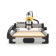
ooznest OX CNC Machine

Discussion in 'CNC Mills/Routers' started by Ryan Lock, Apr 28, 2015.

  1. Jestah

    Jestah Well-Known
    Builder

    Joined:
    Dec 4, 2013
    Messages:
    148
    Likes Received:
    84
    once they are in place back fill the grub screw hole with some clay/playdoh/gum/blutac and then paint with nail polish. You can use a pin to pick out the filler later and still get to your grub screws.

    Or you could get some thread lock and use as directed.

    An other is to upgrade from a grub screw to a small cap screw. They often take a larger key size so you can get more force to lock it down. Consider using thread lock on this system too....

    Good luck!
     
  2. Ryan Turner

    Builder

    Joined:
    Mar 1, 2016
    Messages:
    68
    Likes Received:
    13
    I've been doing this on a laser cutter for some time and I've never found you need to replace them, with a little force the screw comes undone. I'd personally replace the grub screws with standard hex bolts, grubs always seem to easy to strip the head.


    @olecam I'd recommend you do the depth mod. I did mine by milling out some aluminium brackets ( that in itself is a great exercise ) and then adding the 60mm extrusions. 80mm seemed excessive and tbh the z axis wouldn't reach anyway.

    After doing the belt mod and the depth mod I could get a nice big machinists vice on the bed and this enabled me to make some parts for my laser cutter that had a fire. You can get some great quality out of the machine as long as you don't rush in to it ( see pics).

    The holes are drilled manually but the rest is milled out with a 5mm bit including milling the surface.

    IMG_3889.JPG
    IMG_3898.JPG
    IMG_3899.JPG

    Just thought I'd post my first go at v carving too. Its for my Wedding and its on a bit of rough brown oak. Had to get the end off to get it on the machine. There is no way I could have done this without the depth mod. IMG_4050.JPG
     
    Ryan Lock likes this.
  3. olecam

    olecam New
    Builder

    Joined:
    Jun 6, 2017
    Messages:
    30
    Likes Received:
    6
    Hi folks, I have changed the grub screws to 6mm m3 bolts. Problem fixed! Thanks everybody :)

    --
    Olivier
     
  4. olecam

    olecam New
    Builder

    Joined:
    Jun 6, 2017
    Messages:
    30
    Likes Received:
    6
    Ryan, many thanks for the suggestion but sorry I haven't been able to figure out what the depth mod is. Is it something relative to the Z travel? Is there some additional information I could maybe rely on in order to see what that mod consists of? Thanks! :)

    --
    Olivier
     
  5. Ryan Turner

    Builder

    Joined:
    Mar 1, 2016
    Messages:
    68
    Likes Received:
    13
    @olecam You basically buy some 60x20mm extrusions and put these at either end of the router. Join them to the existing extrusions with some flat brackets. The then drop the cross member supports down so you have more useable z travel.

    For instance I have a 6mm two flute router bit with a 28mm cuttable edge. With the standard build, with material on the bed it's difficult to get this bit out of the collet when over the material if needed.

    With the extra z travel by lowering the whole bed it's really easy.
     
  6. Ryan Lock

    Ryan Lock Veteran
    Builder

    Joined:
    Oct 12, 2014
    Messages:
    530
    Likes Received:
    294
    What Ryan said. Or you could turn the spoilerboard supports 90 Degrees and drop them down. Then inset the spoilerboard in between the front and back extrusions.

    Ryan
     
  7. olecam

    olecam New
    Builder

    Joined:
    Jun 6, 2017
    Messages:
    30
    Likes Received:
    6
    Many thanks, guys, for the explanations: everything is now clear with me. TBH I have mistaken "extrusions" with "extruders", this explains why I was out of focus! :) Sorry for that!

    Something completely different: from time to time my xPro Controller (v3) hangs. It is necessary to unplug/plug the USB cable in order to get it working again. I observed that is mainly when the Dewalt 26200 is under respectable load and variable speed is set to 5 or 6 (using 6mm Corn Teeth End Mill which works best in that conditions). I suspected some electromagnetic interferences, and I have added additional ferrite nuts on the Dewalt cables and power supply but nothing doing: the problem remains. Any idea?

    Thanks and best regards,
    --
    Olivier
     
  8. Ryan Turner

    Builder

    Joined:
    Mar 1, 2016
    Messages:
    68
    Likes Received:
    13

    What are you using to control it? Are you connected from a computer directly by USB?
    Do you have limit switches installed? If you do switch off hardware limits and just use homing and software limits.


    I used to have issues using Chillipeppr and JSON on a raspberry pi. Now I remote control the pi and use bcnc as this seems to be better than anything ( even ugc platform ). That said the Pi struggles when loading big files so tomorrow I am getting an old Mac mini as I can use this as a keyboard less, mouse less, monitor less ( aka headless! ) server and it will run anything I throw at it.
     
  9. Ryan Turner

    Builder

    Joined:
    Mar 1, 2016
    Messages:
    68
    Likes Received:
    13
    By the way.

    The reason I said 60x20mm extrusions is that firstly ( as I said ) the z travel isn't long enough otherwise.

    Secondly though, if you put a good solid bit of 18mm mdf on the cross members and use 40x20mm extrusions you aren't left with much depth. I found mdf under 18mm will flex if you put anything weighty on it. Hence the happy medium between 40 and 80 is 60mm.

    Mdf is a pain in the ***. But fine when it's flat. It even bends under its own weight when stored vertically!
     
  10. olecam

    olecam New
    Builder

    Joined:
    Jun 6, 2017
    Messages:
    30
    Likes Received:
    6
    My dedicated (old) laptop is directly connected to the controller, so I don't know actually if this is either at the computer side or at the xpro side. I don't have (yet) any limit switches installed.

    I should try with a remote connection in order to limit electromagnetic interfaces getting back into the electronics. Thanks for suggestion, Ryan! BTW, bCNC seems a good alternative. Ugc platform does the job but I must confess that I'm not 100% happy with its user-friendliness.

    PS: thanks for the tips regarding the Z mods. I agree it's a bit short as is.

    --
    Olivier
     
  11. Ryan Lock

    Ryan Lock Veteran
    Builder

    Joined:
    Oct 12, 2014
    Messages:
    530
    Likes Received:
    294
    For the interference is the router wire running anywhere near the other wires? If possible it would be good to have router power wire going straight up to the ceiling to minimise it causing any issues.
     
    Ryan Turner likes this.
  12. Ryan Turner

    Builder

    Joined:
    Mar 1, 2016
    Messages:
    68
    Likes Received:
    13


    See Ryan's post below. However, it's very usual for you to be getting false triggers with no limit switches etc. AC interference is quite strong compared to DC. Make sure that router cable is no where near that circuit board.

    My machine pauses and carries on every now and again but my nc file is 20mb so it's not suprising.
     
  13. olecam

    olecam New
    Builder

    Joined:
    Jun 6, 2017
    Messages:
    30
    Likes Received:
    6
    I payed attention to separate the DeWALT cable (it goes straight to the to the ceiling, indeed). For now, I reduced roughing step-down a bit, that way the router is less loaded and the USB communications is rock stable. I'll investigate further and let you know if I can find a way to get rid of that problem. When this occurs I have to react very quickly to stop everything in order to prevent the end mills to burn (and then have to reset the home position which is quite annoying) ! :)

    --
    Olivier
     
  14. Ryan Turner

    Builder

    Joined:
    Mar 1, 2016
    Messages:
    68
    Likes Received:
    13
    You can always clean them with a brass brush and a dremel; So don't worry too much. Although fire is never a good outcome!.
     
  15. Ryan Lock

    Ryan Lock Veteran
    Builder

    Joined:
    Oct 12, 2014
    Messages:
    530
    Likes Received:
    294
    Hi,

    We should be getting some Bluetooth modules soon which will hopefully solve these issues :)
     
    olecam likes this.
  16. LeeH

    LeeH New
    Builder

    Joined:
    Aug 23, 2017
    Messages:
    9
    Likes Received:
    0
    Hi, my order for a 1500x1500 ooznest is on its way. I've ordered enough belts for double belting and was wondering if the 3M VHB 4019 tape ( mentioned in this thread) is the best way to stick it down. I've been googling the tape and am getting a little confused. But it seems to be that 4019 and 4910 tape is the same thing depending on the seller. So just to confirm that the tape needs to be 1mm thick and 6mm wide.
     
  17. Gary Caruso

    Gary Caruso OpenBuilds Volunteer
    Staff Member Moderator Builder

    Joined:
    May 19, 2016
    Messages:
    1,194
    Likes Received:
    534
    I think 1mm is too thick, more like 0.5mm is what you want. I used glue for mine with carbon fiber strips as 0.5mm spacers.
    Been running great with no problems.
     
  18. Bjorn Mikkelsen

    Builder

    Joined:
    Jan 22, 2017
    Messages:
    27
    Likes Received:
    1
    Nice carving.
    May I ask a few questions :
    1. How did you hold down such a large piece of wood ?
    2. How long did it take ?
    3. What software did you use ?
    4. What bit / feed / speed / depth of cut did you use ?

    Thanks in advance
     
  19. Bjorn Mikkelsen

    Builder

    Joined:
    Jan 22, 2017
    Messages:
    27
    Likes Received:
    1
    Thats what I have done too, and the added benefit is that turning the supports 90 degrees and mounting my spoilerboard to them have made the machine very rigid.
     
  20. JamieMcC

    JamieMcC New
    Builder

    Joined:
    May 3, 2017
    Messages:
    9
    Likes Received:
    4
    Hi reading through I have seen a couple of posts that mention a mod to get a little more gantry clearance but cant seem to locate any further details with the OB search feature could someone be so kind as to point me in the right direction.
    Cheers

    Edit just found the info thanks
     
  21. Ryan Turner

    Builder

    Joined:
    Mar 1, 2016
    Messages:
    68
    Likes Received:
    13
    So!

    My router bed has threaded inserts that are 6mm. I used 6mm bolts with bits of plywood to stop it moving.

    I didn't need to worry too much about it moving as it's a heavy piece and if you don't cut aggressively it won't move. That said I did make sure it could t move at all when coupled with the hold downs and the 6mm bolts.

    I also didn't do a rough cut I took it carefully. It's a nice piece of oak and you don't want to go too deep and tear away too much material.

    If you go too deep, two things can happen. You cut away your intended material but you also drag away extra material due to the fiberous nature of the material.

    It took about 6 and a half hours but I ran that at a conservative rate. It's a 3mm depth of cut (varies because I didn't face the timber ) and I took off about 1mm at a time. It's the only timber I had so I didn't want to mess it up!

    I used EstlCam which worked it all out for me although I had to do some manual editing and there was a bug in the software I had to work around.

    Feeds and speeds etc...

    It's oak so...

    90 degree chamfer v cutter
    2% step over
    20,000 rpm
    Feed 1427mm/min
    90% incline when plunging with the z axis and a z axis feed of 713mm/min.

    Where did I get this info? I got tired of the mystery of feeds and speeds so I just bought Gwizard for the year. It's so much easier!

    The finished piece looks like this.
    IMG_4111.JPG IMG_4113.JPG
     
    GrayUK and Ryan Lock like this.
  22. NLucier

    NLucier New
    Builder

    Joined:
    Sep 11, 2016
    Messages:
    18
    Likes Received:
    11
    While testing out the grid I plan to route into my spoil board, I have run into a problem that I hope someone is able to say, "Ah ha! I ran into this and here is the solution."

    Quick background: Ooznest 1500x1500 w/ spindle & cncPro V2 (think grbl 0.9?). The grid is solid lines every 10cm and dots at the intersection of every 1cm in between. The grid is planned to start at 1cm from the front-left edge of the spoil board and upper-right is 1cm inside the corner there as well. Should be pretty basic. I am using a 90d V bit at a 1mm depth for the dots and haven't tested depth for the lines due to my problem cropping up and halting my progress for troubleshooting. All g-code is in absolute coordinates (G90). I have tried both Universal G-Code Sender and cncjs, with the same result. I have also installed the ferrous rings on all of the power/signal lines and am using the USB cable that Ooznest sent me (which has solved the other problems I was having with the cncPro going brain dead during operation). The test I am doing is just the first 90mm x 90mm lower-left corner of dots.

    What is happening (shown in the first 2 pictures, first using G0 for rapids, second using G1) is that the first X row of dots is perfect in regards to the first dot being at x10,y10 and each dot in the x-axis being 10mm further through to x90,y10. The next dot to be done is at x10,y20 (g-code by hand so was easier to copy by rows and just change the Y number). When the spindle is told to move to x10,y20, it comes up 1mm short in x travel but fine in y travel (x11,y20). It does that dot and then moves CORRECTLY to x20,y20 (only 9mm) and every other dot to x90,y20 is dead-on at the 10mm interval. This repeats for every row if I'm doing the drilling left-to-right. I have attempted this using both G00 and G01 for the "rapids" with no change in grid dot location. One other thing to note is that at the end, it is commanded to move back to x0,y0 and isn't making it perfectly there either, ending up at about x1,y1 (first picture shows the two dots for beginning and end locations).

    The 3rd picture is attempting to have the router move from x90,y10 to x10,y10 and then up to x20,y10 , but that resulted in no change to the 2nd row of dots. I did have a typo introduced in the g-code that caused the x90,y20 to x10,y30 move to actually go to x10,y0 (with the dot being at x11,y0) and then moving to x20,y30 correctly and finishing that row in the right locations.

    The 4th picture is seeing what happens when it goes 1st row left-to-right and then 2nd row right-to-left, 3rd row left-to-right. It shows that the problem happens at the beginning of each row except row 1, in each direction. The funny thing is that the last dot of row 3 is in perfect position, like it has been in all previous attempts, but also the x0,y0 position is the same at start and end.

    I have checked to make sure the grub screws are tight, and they are (I'm thinking now to change them out for M3 cap screws like I see above in the thread and will do that tomorrow), and I couldn't make any pulley move on its shaft on any motor. The belts are as tight as I would think I would be comfortable making them. I had to adjust them when I skimmed the spoil board a few days ago due to skipping issues that are gone (and may have been due to MDF dust buildup on the rails/wheels anyway).

    One thing I have not done is something like do row 1 and move to row 3 and then down to row 2 to see if the Y axis has the same problem. I will probably do that tomorrow though, just to satisfy my curiosity.


    TL;DR: Making a 1cm grid, the left column of squares is 9mm wide, not 10mm, EXCEPT the first dot in the column. All other squares are correctly 10mm in height/width.


    Does anyone have any ideas as to what is going on?

    1-0904172133-marked.jpg 2-0904172133a-marked.jpg 4-0904172133c-marked.jpg 5-0904172134-marked.jpg


    G-Code used for the first picture is below. Second picture used the same code, but G1 for all moves (and took a lot longer). Adjustments were made to change the direction of travel for the last two, going back to G0 for the moves since that made no difference.

    G90
    F900
    G1 Z3.00
    G0 X10.0 Y10.0
    G1 Z-1.0
    G1 Z3.00
    G0 X20.0 Y10.0
    G1 Z-1.0
    G1 Z3.00
    G0 X30.0 Y10.0
    G1 Z-1.0
    G1 Z3.00
    G0 X40.0 Y10.0
    G1 Z-1.0
    G1 Z3.00
    G0 X50.0 Y10.0
    G1 Z-1.0
    G1 Z3.00
    G0 X60.0 Y10.0
    G1 Z-1.0
    G1 Z3.00
    G0 X70.0 Y10.0
    G1 Z-1.0
    G1 Z3.00
    G0 X80.0 Y10.0
    G1 Z-1.0
    G1 Z3.00
    G0 X90.0 Y10.0
    G1 Z-1.0
    G1 Z3.00

    G0 X10.0 Y20.0
    G1 Z-1.0
    G1 Z3.00
    G0 X20.0 Y20.0
    G1 Z-1.0
    G1 Z3.00
    G0 X30.0 Y20.0
    G1 Z-1.0
    G1 Z3.00
    G0 X40.0 Y20.0
    G1 Z-1.0
    G1 Z3.00
    G0 X50.0 Y20.0
    G1 Z-1.0
    G1 Z3.00
    G0 X60.0 Y20.0
    G1 Z-1.0
    G1 Z3.00
    G0 X70.0 Y20.0
    G1 Z-1.0
    G1 Z3.00
    G0 X80.0 Y20.0
    G1 Z-1.0
    G1 Z3.00
    G0 X90.0 Y20.0
    G1 Z-1.0
    G1 Z3.00

    G0 X10.0 Y30.0
    G1 Z-1.0
    G1 Z3.00
    G0 X20.0 Y30.0
    G1 Z-1.0
    G1 Z3.00
    G0 X30.0 Y30.0
    G1 Z-1.0
    G1 Z3.00
    G0 X40.0 Y30.0
    G1 Z-1.0
    G1 Z3.00
    G0 X50.0 Y30.0
    G1 Z-1.0
    G1 Z3.00
    G0 X60.0 Y30.0
    G1 Z-1.0
    G1 Z3.00
    G0 X70.0 Y30.0
    G1 Z-1.0
    G1 Z3.00
    G0 X80.0 Y30.0
    G1 Z-1.0
    G1 Z3.00
    G0 X90.0 Y30.0
    G1 Z-1.0
    G1 Z3.00


    G0 X0.0 Y0.0
    M30
     
  23. OldDogSleeping

    Builder

    Joined:
    Oct 22, 2015
    Messages:
    11
    Likes Received:
    11
    Nlucier,

    You could try changing your G-code so that the points are always approached from the same direction. So when moving from row 1 to row 2 Go to X0,Y20 before moving to X10,Y20.

    if this corrects the problem, you're looking for a backlash issue, i.e. something loose/stretching on the X-axis movement. you will always have some backlash but 1mm is excessive, my OX has less than 0.15mm on the X-axis.

    if the problem is still there when approaching the points from the same direction , I'd be checking the Y-rails and carriages for something bent.
     
    NLucier likes this.
  24. Gary Caruso

    Gary Caruso OpenBuilds Volunteer
    Staff Member Moderator Builder

    Joined:
    May 19, 2016
    Messages:
    1,194
    Likes Received:
    534
    Probably wheels are too tight, causing backlash or missed steps.. also on a 1500x1500 you are crazy not using dual-belt IMO
     
    NLucier likes this.
  25. Ryan Lock

    Ryan Lock Veteran
    Builder

    Joined:
    Oct 12, 2014
    Messages:
    530
    Likes Received:
    294
    As it looks to be on direction changes, i would think it is a backlash issue. Maybe the pulleys slipping? Try cutting a circle, and see if it comes out irregular.
     
    NLucier likes this.
  26. NLucier

    NLucier New
    Builder

    Joined:
    Sep 11, 2016
    Messages:
    18
    Likes Received:
    11
    I cannot see/feel the pulley slipping on the X, but I'll be replacing the grub screws on all of them with cap screws just so that I can make better sure that they are tight. When I did a circle test a while ago, a meter diameter circle was perfect when measured through the center point all around. It was only during this grid attempt on the spoil board that this came to light. It smells of backlash, but I can't see it at the moment. I will try the screws and also belt again on the X.

    I do have the belts to do the dual-belt, just haven't tried to attach them yet as when I got the second set of belts with the kit, I couldn't really find a how-to on doing it. I see now that I'm supposed to adhesive it down to the rail from reading other posts in this thread.

    More troubleshooting later today
     
  27. NLucier

    NLucier New
    Builder

    Joined:
    Sep 11, 2016
    Messages:
    18
    Likes Received:
    11
    Success! The grid is now 1cm junctions all around when I made a test while having the spindle move into dots from all directions to check both directions of X and Y movement.

    Grub screws replaced and I feel much better about the M3 socket cap screws as they feel more positive when tightening. Before replacing them I looked as carefully as I could to see if any pulley was moving on the motor shaft and I couldn't detect any. I went ahead and replaced w/ thread locker anyway for the feel-good aspect.

    The main problem was indeed that the wheels on all moving parts were TIGHT! I don't remember tightening them anywhere near what they were, but it suddenly occurred to me that I built the thing on the kitchen table (with permission...with permission), in the wonderful inside temperature of 72F (22C). I happen to live in Arizona where today was 106F (41C) {and our high this summer was 123F (55.5C)}. Since the router is in the garage, I'm thinking that I have a little thermal expansion that has happened and I need to periodically check for. the X and Y move so much more smoothly now and the Y and A ends of the gantry don't fight each other now, just move in tandem.

    Thanks everyone that gave me some things to check. I will be working towards doing the dual-belt thing eventually, but I want to see this thing making some stuff before I start modding it more than I have already (mounting to the wall and such). Can't wait to see it make the real grid now on the spoil board as the test looks great.
     
    olecam and Ryan Lock like this.
  28. Marcus1

    Marcus1 New
    Builder

    Joined:
    Jan 13, 2017
    Messages:
    65
    Likes Received:
    13
    OK

    So now in my 8th Month of tuning my 1500x1500 OX Machine
    Lessons learned and things still to solve

    Thanks to all on here for getting me so far
    Must Do Mods
    1. Double Belt
    2. Better screws on the GT3 Pulleys

    Worthwhile mods
    1. Vaccuum Table
    2. Servo Stepper upgrade

    All seems to be running OK ish
    Kit
    1500 Router, vaccuum table, Mach 3, servo Steppers 475 oz inch (set to ES on error), double belted, 2.2kw 3 phase with VFD Spindle (controlled through Mach 3), Vetric V carve 9
    Cutting Strategy
    Roughing 3600mm/min 16000rpm, cutting depth less than cutter dia - tabs 1 off on each profile
    Finishing 2000mm/min 16000rpm 5mm cutting depth (3mm cutter) up to 1.2mm finishing width
    Material - MDF 9mm and 15mm - looking at cutting Birch ply but need more confidence in what is happening before moving on.

    I cut patterns in mdf.
    Problem...
    generally cuts and finish is good. However, at most points the finishing cut leaves a witness line (30 deg ramp down to level over 15mm) and (mainly in the X direction) the finish pass in 2 depth cuts leaves the 2nd cut with a step in the material edge.
    I am now sure I am NOT losing steps.
    Is this an issue with ramping in a 3mm cutter (distortion on plunge) or backlash or something else?

    Issue 2 - occasionally there seems to be a "wave" on the finished cut edge. I cannot see any reason for this but can only put it down to to much flex in the X gantry/ Z axis.

    Any pointers appreciated.

    In regards to issue 2 , are there any strengthening suggestions that have worked for you?

    Cheers

    Marcus
     
  29. Ryan Lock

    Ryan Lock Veteran
    Builder

    Joined:
    Oct 12, 2014
    Messages:
    530
    Likes Received:
    294
    Hi,

    For issue 2 the only thing you can do is use small bolts and tee nuts to join the two 20x60mm rails together, so they don't act independently.

    I am not sure about the witness cut. What are the details of the 3mm bit you are using for finishing?

    Ryan
     
  30. Bjorn Mikkelsen

    Builder

    Joined:
    Jan 22, 2017
    Messages:
    27
    Likes Received:
    1
    Hi all,

    I have the OX 750x1000mm. Running the NEMA 23, xPRO v3 and a 24v powersupply. (all bought from Oozenest). I have over the last ½ year been adding stuff to the cnc like limitswitches, homing, dual belts, dustshoes etc. BUT I constantly keep running into issues with it not running as I want.

    Challenges I have (and have been having for a long time) :
    - When moving along the x-axis I hear/feel bumps. BUT only when its doing a job, I dont feel/see it when moving the axis by hand or when jogging it. Its regulary bumps, like a flat spot on one wheel, but I dont see/feel any, and if it was it should be there all the time ?
    - Chatter/shakes. When running a job with a feed of under around 800mm the machine (and spindle) shakes quite alot. Running between 1000-2500mm the machine runs alot better it seems.
    - It seems like as soon as the machine meet some resistance (like 1mm facing with a 1inch bit), it begins to run poorly/unreliable. I have tried to adjust the current/amp from 0.9 to 1.2 and I hope it helps.

    When I see other people making videos of their OX it runs butter smooth, how / what am I missing ?

    I have read these threads many times, alot of other forums/threads, and have tried whatever I could find that might help out.

    Thanks in advance
     

Share This Page

  1. This site uses cookies to help personalise content, tailor your experience and to keep you logged in if you register.
    By continuing to use this site, you are consenting to our use of cookies.
    Dismiss Notice