Welcome to Our Community

Some features disabled for guests. Register Today.

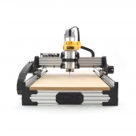
ooznest OX CNC Machine

Discussion in 'CNC Mills/Routers' started by Ryan Lock, Apr 28, 2015.

  1. Bjorn Mikkelsen

    Builder

    Joined:
    Jan 22, 2017
    Messages:
    27
    Likes Received:
    1
    The most important thing is that it works. But for me doing what Gary advised (putting 0.5mm under the lower belt and gluing it) made a HUGE difference in how well it runs.
     
  2. NeoMorph

    NeoMorph New
    Builder

    Joined:
    Jul 1, 2017
    Messages:
    68
    Likes Received:
    20
    I mostly loving my Ooznest OX build but while everything in packaged lovely and the cuts are perfect in quality and precision there is one thing that lets it down... and that is one of the 3D printed parts.

    It’s sharp as razor blade, nut holes have sagged and full of filaments which means I had to spend an age clearing out the mess with a Dremel. It’s like their 3D printer was on its last legs. But luckily it’s only on the one part of the drag chain. Dremel + sanding + primer and paint sorted that.

    But one thing in the build nearly caught me out. The voltmeter that was included wasn’t checked and there are hair thin wires poking out the connectors (see image attatched) that could very easily short out. I only spotted them with my reading glasses on. Now more than likely they would either trip the short detection or just burn out the first time they short... but for this much money they should have been checked better.

    But generally, bar these few niggles this build has been fun. I still haven’t finished (I’m slow because my disability limits how much time I can devote to it every day) but I am also including some custom bits that I wanted to add to my machine (like computer speed controller for the Dewalt 611 and Manual Pulse Generator). Ironically I managed to sort those out quick yet have had LOADS of trouble finding connectors to fit my 63mm flexible pipe for the vacuum system (but nothing that copious amounts of duck tape can’t fix).
     

    Attached Files:

  3. Ryan Lock

    Ryan Lock Veteran
    Builder

    Joined:
    Oct 12, 2014
    Messages:
    530
    Likes Received:
    293
    @NeoMorph My apologies for the issues, if you need anything we can sort you out. Which plastic part are you referring to, the y moving drag chain mount i think?
     
  4. NeoMorph

    NeoMorph New
    Builder

    Joined:
    Jul 1, 2017
    Messages:
    68
    Likes Received:
    20
    It’s the “Y Drag Chain Moving End Mount”. As you can see in the picture you can see it’s distorted and was sharp as a razor until I filed it down... but the main problem was getting the nuts in the holes as they were full of filament and getting the Dremel in there was a nightmare due to the angle of the shelf. It’s the only part that was problematic and I was humming and ahhing whether to get a replacement from you but in the end I decided it was okay until I can make one out of aluminium. The wires to the voltmeter were more worrying which is why I triple checked all the electrics but that was the only problem. It’s easy to miss in bad light.

    Buy out of everything, just one bad print and one untrimmed wire part... I’m still happy. I just rather tell people how it is, the good with the bad, and there is a heck of a load more good than bad.
     

    Attached Files:

  5. Ryan Lock

    Ryan Lock Veteran
    Builder

    Joined:
    Oct 12, 2014
    Messages:
    530
    Likes Received:
    293
    Hi,

    Yes that is fair enough, i prefer to know the issues so we can improve. I can send you out a new plastic part if you want. I have been checking the prints today for the same issue, so glad you made me aware.

    Ryan
     
  6. NeoMorph

    NeoMorph New
    Builder

    Joined:
    Jul 1, 2017
    Messages:
    68
    Likes Received:
    20
    That would be great Ryan... it’s silly that it’s niggling at me after everything else was so perfect but every day I come into the room my eyes immediately are pulled to look at it. Touch of OCD on my part I think heh.

    Personally I think the cause was my bad luck lately. For example last night I dropped my Kindle Voyage, bent down to pick it up and my leg spasmed due to my disability. I took one step forward automatically to stop falling over and heard CRRAAACK! Yup, £170 Kindle cracked right across.

    So yeah, thanks for the offer. I’ll take it because with my luck my fixed one will probably burst into flames and explode.

     
  7. olecam

    olecam New
    Builder

    Joined:
    Jun 6, 2017
    Messages:
    30
    Likes Received:
    6
    Hi -

    I was wondering if it would be easy to install limit switches on the new Workbee machine. Is there some space/mouting provided for this?

    Tks and best regards,
    --
    Olivier
     
  8. NeoMorph

    NeoMorph New
    Builder

    Joined:
    Jul 1, 2017
    Messages:
    68
    Likes Received:
    20
    This may be a bonkers simple question but how do people attach their spoilboards? I’m approaching the end of my build and just realised I’ve not got any t-nuts on the top of my v-slot supports you see (did I miss a step somewhere?).
     
  9. olecam

    olecam New
    Builder

    Joined:
    Jun 6, 2017
    Messages:
    30
    Likes Received:
    6
    I had to bought some t-nuts to attach my spoil board to the frame. BTW, maybe Ryan should add a fixation kit as an option (or always include it in the shipping) in order to draw attention that it might be necessary to stock additional screws and t-nuts for that purpose? Just a thought... ;)

    --
    Olivier
     
  10. NeoMorph

    NeoMorph New
    Builder

    Joined:
    Jul 1, 2017
    Messages:
    68
    Likes Received:
    20
    9784FB6E-79E6-487A-8F24-8D66A30CCA14.jpeg I actually had to look through the (awesome) instructions again just to realise I hadn’t missed it.

    I did however spot a funny spelling mistake... either that or I’ve got to buy a new home to be safe when using this CNC.

    I’m probably going to bolt the board to the table along with the frame. That way I know it’s solid. I made the units specifically for the CNC you see.


  11. Ryan Lock

    Ryan Lock Veteran
    Builder

    Joined:
    Oct 12, 2014
    Messages:
    530
    Likes Received:
    293
    @NeoMorph Could you pm me over your Order id and i will get it sorted. Thanks for pointing that out. I am afraid we don't provide fixations for the spoilerboard. Maybe it is something we should look into.

    @olecam Yes, the Z-Axis has threaded holes to mount them without loosing in Z Cut depth. And the X and Y can be mounted using the Limit switch kits.
     
  12. olecam

    olecam New
    Builder

    Joined:
    Jun 6, 2017
    Messages:
    30
    Likes Received:
    6
    Great news, Ryan, thanks! I'll place my order for an upgrade very soon. Is there any parts I should include for the Z-axis? Maybe a microswitch?

    --
    Olivier
     
    #852 olecam, Oct 11, 2017
    Last edited: Oct 11, 2017
  13. NeoMorph

    NeoMorph New
    Builder

    Joined:
    Jul 1, 2017
    Messages:
    68
    Likes Received:
    20
    Even suggestions would help but for a newbie like me it was a head scratcher. I knew I needed a spoilboard at least heh.

    It’s been a slow build but I’m nearly there. Had to remove one of the waste board supports temporarily last night because I hadn’t got enough T-nuts to anchor the belts but had a load of drop in T-nuts left over.

    The electronics are taking time because I’ve housed them in a shielded case. I’ve also included the optoisolator board for the limit switches in there never liked the idea of a board sitting in the open, especially as I will be cutting acrylic. I have this image of static buildup like stroking a cat... so everything is shielded, earthed and ferrit bead protected (belt and braces approach). Will have to see if it works.
     
  14. NeoMorph

    NeoMorph New
    Builder

    Joined:
    Jul 1, 2017
    Messages:
    68
    Likes Received:
    20
    Just put the final bits together and realised that either the Ox is designed to do without the spoilboard supports or ive built it wrong because the Z gantry comes down and touches the supports WITHOUT A SPOILBOARD.

    Have I built it wrong?

    Edit: Just done some research and it seems it was built with such an area underneath the spoilboard to build in a vacuum table. I think I’m just going to put down several pieces of MDF which will bring the level up and allow full travel of the Z axis without crashing into the table. Plus it gives extra weight to the table AND means I have 5 replacement spoilboard surfaces.
     
    #854 NeoMorph, Oct 12, 2017
    Last edited: Oct 12, 2017
  15. Gary Caruso

    Gary Caruso OpenBuilds Volunteer
    Staff Member Moderator Builder

    Joined:
    May 19, 2016
    Messages:
    1,193
    Likes Received:
    532
    Having to disassemble and re-assemble many times due to forgotten T-nuts is an openbuilds right of passage! So you are doing it right ;)
     
    NeoMorph likes this.
  16. Ryan Lock

    Ryan Lock Veteran
    Builder

    Joined:
    Oct 12, 2014
    Messages:
    530
    Likes Received:
    293
    @olecam If you buy the upgrade kit, the limit switches will be included.

    @NeoMorph The Z-Axis can each down further than the spoiler supports. Doing as you suggested is a good way to gain extra cutable depth.
     
  17. NeoMorph

    NeoMorph New
    Builder

    Joined:
    Jul 1, 2017
    Messages:
    68
    Likes Received:
    20
    Well I’ve got the bits now... just waiting for my nylon bolts to arrive.

    Got plenty to do with the unit though because I’m encasing it in a soundproof shell as I live in a terrace. I’ve got a SuperPID to control the speed remotely too so that’s helping with the noise levels. Even lets me drop it down to 5000 rpm on the Dewalt... both manual and computer control options.

    One of the first jobs I plan to do is make a Controller Panel for the shortcut keys, speed controller and the cheap MPG dial I got off eBay. Was surprised at how easy it was to get working to be honest. Am I overdoing my build... probably... but I’m as interested in building it as I will be making stuff with it and I have to say that I really loved building the Ooznest kit. It’s the clearest build manual I’ve come across in... forever and one came across one spelling mistake and one sequence oversight (mainly to do with buying the full kit as the manual was just listing the mechanicals.

    I’ve made several changes to protect the Xpro and isolate it from electrical noise. I’ve also made it fully computer controlled by the SuperPID. But ultimately I want to make it remote controlled to so that it can send me alarms when it shuts down or I can check on it via a camera to my phone and a remote fob will let me shut down the the machine like hitting an emergency stop. Belt and braces. One thing I would love to do is a home brew toolbreak detection system because if you are cutting for hours and a tool breaks and you are air cutting... well, what a waste of time.
     
  18. NeoMorph

    NeoMorph New
    Builder

    Joined:
    Jul 1, 2017
    Messages:
    68
    Likes Received:
    20
    Thanks for that Gary... I thought I was being a brain fogged numpty again lol.
     
  19. NeoMorph

    NeoMorph New
    Builder

    Joined:
    Jul 1, 2017
    Messages:
    68
    Likes Received:
    20
    8E321DF5-9009-438A-9515-44930373B2B2.jpeg Question: X and Y axes....

    It was originally my view that the Y axis was along the gantry and the long side (I have a 1000 x 750 version) was the X axis... but the wiring is opposite that.

    On most mills I’ve looked at the x axis is along the bed from left to right. Y axis is from front to back.

    It’s a minor change to the wiring and move the clone jumper from Y to X but I was was wondering why it was shipped reversed. I thought it was a fault with the electrical manual manual at first but the XPro is shipped with the default being the Y axis.

    Am I missing something (sorry to be such a niggle).
     
    #859 NeoMorph, Oct 12, 2017
    Last edited: Oct 12, 2017
  20. Rick 2.0

    Rick 2.0 OpenBuilds Team
    Staff Member Moderator Builder Resident Builder

    Joined:
    Dec 20, 2013
    Messages:
    2,894
    Likes Received:
    1,552
    You are correct but you have to be looking at the machine from the right direction. The photo at the top of the page shows the front of the machine with front to back Y-axis rails at the sides and left to right X-axis gantry beam across the top.
     
  21. NeoMorph

    NeoMorph New
    Builder

    Joined:
    Jul 1, 2017
    Messages:
    68
    Likes Received:
    20
    That photo is looking along the X axis from everything I’ve looked at. Yet the Ox seems to be shifted 90 degrees.

    Like I said, simple fix because all my designs on Fusion 360 are done with the X being longer than the Y or I would just leave the Ox as designed. It’s just easier to rewire the XPro than go through and change all the 3D models I’ve worked on.
     
  22. NeoMorph

    NeoMorph New
    Builder

    Joined:
    Jul 1, 2017
    Messages:
    68
    Likes Received:
    20
    Well I have got it moving... yay... but the dual motor axis (I’ve set it to X) is noisy as hell.

    I think there might be a friction problem or something because when I set it jog to 1 and tap the jog button it doesn’t move. Tap again and still no move... yet on the third tap it moves. Tap again, no move, no move, move. It moves every third tap.

    So tomorrow I’m going to see what happens when I loosen the gantry way off and see how that affects it.
     
  23. lees76

    lees76 New
    Builder

    Joined:
    May 29, 2016
    Messages:
    15
    Likes Received:
    3
    Looking for peoples opinion on the 1.5kW Air cooled CNC spindles with VFD on Amazon

    https://www.amazon.co.uk/dp/B019NYM79K/_encoding=UTF8?coliid=I2323LUAWC1PK8&colid=RRPAS6PYBXKA

    • Are they any good
    • Are they easy to set up (using mach3)
    • Are dust shoes redily available, the ooznest dustshoe is 71mm and these are about 65 mm
    • What ER collet size should i be looking at?, I am currently using the DW26200 router and my Bit collection all have 1/4" and 1/8" shanks.
    Thanks for any help!
     
  24. Marcus1

    Marcus1 New
    Builder

    Joined:
    Jan 13, 2017
    Messages:
    65
    Likes Received:
    13
    Lees

    I bought a similar one from Ebay (2.2Kw Version).
    1. I have been using mine for 9 months now, with no issues. (touch wood)
    2. Took ages to set up with Mach 3 - But I now have the settings and can provide if you need them. I can control the speed through Mach and it switches on and off through the G code. Make sure you get a break out board with a spindle solenoid.
    3. I have printed a dust shoe - can supply the stl or part
    4. The collet will give you the flexibility to have (up to) 12mm shank sizes. You can buy sets cheap on flea bay. Each collet has a 1mm range

    Main issues
    Get good quality shielded cable for power supply (4 Core)- got mine from Zapp automation ( for the motors aswell)
    Mounting the spindle - I printed two mounts from thingyverse and mounted them on Z axis. All is good but adjusting the spindle for trueness vertically is difficult as the screws are behind the spindle.

    Hope that helps
     
  25. Marcus1

    Marcus1 New
    Builder

    Joined:
    Jan 13, 2017
    Messages:
    65
    Likes Received:
    13
    Lees

    PS - Mine has an ER20 Collet, not ER11 . ER 11 may restrict the sizing down a bit. I wanted to fit at least 1/2" Cutters (Spoilboard surfacing cutters are more robust in this size)
     
  26. lees76

    lees76 New
    Builder

    Joined:
    May 29, 2016
    Messages:
    15
    Likes Received:
    3

    Thats a huge help thanks, Did you go for the air cooled or water cooled?
     
  27. Marcus1

    Marcus1 New
    Builder

    Joined:
    Jan 13, 2017
    Messages:
    65
    Likes Received:
    13
    Went for Air cooled. reports on the net said that these were just as reliable and not so messy.
    Have run the spindle for 7 Hours at a time at 21000rpm - it gets warm but not too hot to touch (especially in summer).
    If I have any concerns I put a fan near the machine. Steppers and Vacuum pumps get hot aswell!
     
  28. NeoMorph

    NeoMorph New
    Builder

    Joined:
    Jul 1, 2017
    Messages:
    68
    Likes Received:
    20
    So wish I had gone with a proper spindle... but I’ve got this system working for me now and have a 5000 to 30000 rpm controllable from GRBL... with a Dewalt 611.
     
  29. lees76

    lees76 New
    Builder

    Joined:
    May 29, 2016
    Messages:
    15
    Likes Received:
    3
    I'm not keen on having a bucket of water near the machine, no matter how careful i am.

    CE 2.2KW ER20 AIR-COOLED SPINDLE MOTOR AND 2.2KW INVERTER DRIVE VFD CNC | eBay

    Is this the type you have?, I'm hovering over the buy button now!
     
  30. Marcus1

    Marcus1 New
    Builder

    Joined:
    Jan 13, 2017
    Messages:
    65
    Likes Received:
    13
    Lees

    I bought from this seller
    3013happyshop | eBay

    Loads of others available. Couldnt tell you which is best. I got all documentation from the web. But to understand it you need a degree in Chiglese

    Dont forget the BOB - It MUST have a spindle solenoid!!! I did!!
     
    NeoMorph likes this.

Share This Page

  1. This site uses cookies to help personalise content, tailor your experience and to keep you logged in if you register.
    By continuing to use this site, you are consenting to our use of cookies.
    Dismiss Notice