Welcome to Our Community

Some features disabled for guests. Register Today.

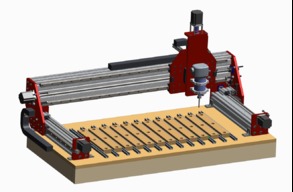
RigidOko

Discussion in 'CNC Mills/Routers' started by SecretSpy711, Oct 16, 2017.

  1. SecretSpy711

    SecretSpy711 Well-Known
    Builder

    Joined:
    Jan 29, 2015
    Messages:
    31
    Likes Received:
    27
    Rijad likes this.
  2. SecretSpy711

    SecretSpy711 Well-Known
    Builder

    Joined:
    Jan 29, 2015
    Messages:
    31
    Likes Received:
    27
    Working on re-designing the Z axis. There are some aspects of the CNCnewbie units that I don't like, so I now plan to make my own using probably 20mm profile linear guide (same as used on X and Y), and 3/8 leadscrew (using the excess cut from my Y screws possibly).

    Haven't decided whether I want to go for the full 4 bearing setup, or use 2 of the long variety bearings.
     
  3. SecretSpy711

    SecretSpy711 Well-Known
    Builder

    Joined:
    Jan 29, 2015
    Messages:
    31
    Likes Received:
    27
    Also reconsidering my bearing setup to capture the leadscrew. The bearing blocks I bought from servocity are looking pretty wimpy.

    Here's the bearing blocks I bought for the X axis:
    1/2" Bore, Face Thru-Hole Pillow Block

    I believe it uses this bearing:
    http://www.product-config.net/catalog3/output/82052925/specsheet.pdf. Static load rating of 71 lbs, and I have 2 of them. Should theoretically be enough but I'm more worried about the fact that they are so thin and I am not planning on turning down my leadscrew

    Considering something more like this, and I wish I had seen it sooner:
    1/2" Two Bolt Flange Bearing UCFL201-08
     
  4. Marshy

    Marshy New
    Builder

    Joined:
    Dec 27, 2015
    Messages:
    2
    Likes Received:
    0
    Hi secret spy what program did you design the machine in?
     
  5. SecretSpy711

    SecretSpy711 Well-Known
    Builder

    Joined:
    Jan 29, 2015
    Messages:
    31
    Likes Received:
    27
    Creo
     
  6. SatMike

    SatMike New
    Builder

    Joined:
    Feb 12, 2015
    Messages:
    27
    Likes Received:
    5
    Would you be interested/willing in sharing your build files? I've been piecing together the components to make a very similar system, and would love to take a closer look at your plates and potentially use them as a starting point.

    Thanks.
     
  7. SecretSpy711

    SecretSpy711 Well-Known
    Builder

    Joined:
    Jan 29, 2015
    Messages:
    31
    Likes Received:
    27
    Sorry for the delay, I hadn't checked the thread in a while since I haven't been able to work on this recently. I will see about posting files when I get some time.

    The Z axis long-version bearings and rail just arrived, so I can make some more progress soon. I was waiting until after the holiday bills had passed before buying the motors and drivers, then the machine will be mostly complete. I also still need drag chain, a motion controller and Mach3 software. I was also considering getting some more extrusions for the base instead of mounting it directly to my wood torsion box.
     
  8. Andreas Bockert

    Andreas Bockert Well-Known
    Builder

    Joined:
    Oct 1, 2017
    Messages:
    142
    Likes Received:
    78
    This does look very slick! The red is awesome.

    Could you show more of your Z-axis?
     
  9. SecretSpy711

    SecretSpy711 Well-Known
    Builder

    Joined:
    Jan 29, 2015
    Messages:
    31
    Likes Received:
    27
    sure, I'll take some pictures when I get home. CAD might be easier since I can hide parts. Basically it's the reverse of many designs here. The Z rails are bolted to the back of the Z plate, and the linear bearings are mounted to the X carriage plate. So the entire Z plate and motor move up and down. This makes the Z axis taller overall, but more rigid. Thanks to Florian Bauereisen for that suggestion.
     
    GrayUK likes this.
  10. Andreas Bockert

    Andreas Bockert Well-Known
    Builder

    Joined:
    Oct 1, 2017
    Messages:
    142
    Likes Received:
    78
    Uuuh... mind... blown...

    I would love an explanation for how it becomes more rigid.

    You might just have caused a redesign on my side. Can’t wait to see your solution.
     
    #10 Andreas Bockert, Sep 19, 2018
    Last edited: Sep 19, 2018
  11. Andreas Bockert

    Andreas Bockert Well-Known
    Builder

    Joined:
    Oct 1, 2017
    Messages:
    142
    Likes Received:
    78
    Ok, so, please help me think this through correctly.

    One benefit is that you can let the "rail side" move below the X-beam. This would at the allow you to mount the router higher up (and make it easier to attach a second mount for the router if desired). It should also give the possibility for a lot more travel along Z.

    I can also see a benefit to the rail blocks being mounted symmetrically w.r.t. the X axis. At least in my case, this would be approximately the case anyway.

    The big drawback would be the added weight that the stepper needs to move...
     
  12. SecretSpy711

    SecretSpy711 Well-Known
    Builder

    Joined:
    Jan 29, 2015
    Messages:
    31
    Likes Received:
    27
    Here's a view looking at the back of the Z axis. You can see the rails bolted to the plate which act like stiffening ribs. The 2 bearings and short piece of 80/20 that holds the lead-nut (actually 1"x2") bolt to the X carriage plate. Since I only have 2 bearings here instead of 4, I am using the "long" versions which are about 3.5" compared to the standard length (about 3") everywhere else on by build. I am using a piece of 3/8-8 4-start leadscrew (0.5" travel/rev), and the Z carriage *almost* falls down when power is removed from the motor, but not quite. A small spring, or a slower leadscrew would fix that.
    rigidoko_z.jpg
    There is a flaw in this design that I've found, which is this: if there is enough force in the Z direction, the piece of 80/20 could potentially slide up and down, causing lost steps. It is mounted using sliding T nuts. You can barely see those T nuts here:
    IMG_20180919_192025.jpg

    That means I need to really, really make sure that these 4 bolts are tight, and if that's not enough then I might bond the piece of 8020 to the X carriage plate or try to machine a different lead-nut bracket that doesn't use sliding T nuts.
    IMG_20180919_192102.jpg
     
  13. SecretSpy711

    SecretSpy711 Well-Known
    Builder

    Joined:
    Jan 29, 2015
    Messages:
    31
    Likes Received:
    27
    I also have several sets of holes on my Z plate so I can mount the router clamps at various heights.
    IMG_20180919_191954.jpg
     
  14. Andreas Bockert

    Andreas Bockert Well-Known
    Builder

    Joined:
    Oct 1, 2017
    Messages:
    142
    Likes Received:
    78
    Did you cut the mounts as well?
     
  15. SecretSpy711

    SecretSpy711 Well-Known
    Builder

    Joined:
    Jan 29, 2015
    Messages:
    31
    Likes Received:
    27
    Yes, on my old machine, very slowly.
     
  16. Andreas Bockert

    Andreas Bockert Well-Known
    Builder

    Joined:
    Oct 1, 2017
    Messages:
    142
    Likes Received:
    78
    I'm considering milling new router mounts. Right now I'm considering if I should go with 1/2" or 3/8".

    Did you use 3/8" or 1/2"stock? Do you find them rigid enough?
     
  17. SecretSpy711

    SecretSpy711 Well-Known
    Builder

    Joined:
    Jan 29, 2015
    Messages:
    31
    Likes Received:
    27
    They were from 1/2" stock but the piece they were made from was bent a little, so they are probably more like 0.45" now since I faced it first.

    3/8 should be fine if they are spaced apart. If they are close together go thicker.

    What I don't like about these mounts is that the mouting holes are behind the router, so I can't remove the mounts unless I first remove the router. (They were originally made to fit a Shapeoko 2's Z plate and I cannibalized them for the new machine.) Also, tramming is difficult with this arrangement, and tightness of the clamp affects the tramming. I plan to re-design these mounts at some point.
     
    #17 SecretSpy711, Oct 13, 2018
    Last edited: Oct 13, 2018
  18. Andreas Bockert

    Andreas Bockert Well-Known
    Builder

    Joined:
    Oct 1, 2017
    Messages:
    142
    Likes Received:
    78
    Ok,
    Thanks for the info. My idea is to use 2 mounts. Each held by 2 m5s from the front. Especially with tramming in mind. It feels like I would like to have more screws in the mount but I’m guessing that this is newbie overbuilding talking.

    I think I’ll use 1/2”.
     
  19. arcrunner

    arcrunner Well-Known
    Builder

    Joined:
    Jul 19, 2018
    Messages:
    48
    Likes Received:
    37
    Looks great! So from what I understand, you used your old machine to basically mark the centers of the holes and then finish drilling with a drill press and cutting out the shape/profile with other tools?
     
  20. SecretSpy711

    SecretSpy711 Well-Known
    Builder

    Joined:
    Jan 29, 2015
    Messages:
    31
    Likes Received:
    27
    Yep, pretty much. I did most of the outside profiles with a sliding miter saw, then filed the corners round.
     
    GrayUK likes this.
  21. Mark Carew

    Mark Carew OpenBuilds Team
    Staff Member Moderator Builder Resident Builder

    Joined:
    Jun 28, 2013
    Messages:
    2,758
    Likes Received:
    2,440
    Great looking Build @SecretSpy711 ,this monster looks like it can blast through aluminum with no problems.
     
  22. Sambaluga

    Sambaluga New
    Builder

    Joined:
    Nov 27, 2019
    Messages:
    1
    Likes Received:
    0
    Hi!

    Total beginner here, currently planing my own CNC machine. Reading through this super interesting build log, I have two questions.

    1. @SecretSpy711 , you call your machine "RigidOko", because, well, you want a more rigid version of your Shapeoko. But wouldn't it be more rigid if you swapped the lengths of the X and Y axes? If the X axis were only 500mm wide, the gantry could withstand larger loads with less flex. The Y axis on the other hand, is fully supported, so it shouldn't matter much, if it were 1200mm long instead of 500mm. Or am I wrong?

    2. My second question is much more general. I'm not very familiar with the imperial system. Sometimes I read things like "3/8-8, 4-start lead screw" or "1/2-10, 5 start lead screw". I understand that 3/8 and 1/2 refers to the diameter of the lead screw in inches, but what do the "-8" and "-10" suffixes mean?
     
  23. Peter Van Der Walt

    Peter Van Der Walt OpenBuilds Team
    Staff Member Moderator Builder Resident Builder

    Joined:
    Mar 1, 2017
    Messages:
    15,051
    Likes Received:
    4,313
    Pitch (distance per rotation) - suspect that might be metric (unlikely to be a 8 or 10 inch pitch, 8-10mm makes more sense)
     
    Sambaluga likes this.
  24. arcrunner

    arcrunner Well-Known
    Builder

    Joined:
    Jul 19, 2018
    Messages:
    48
    Likes Received:
    37
    It would definitely be more rigid if you switch the x and y axis lengths, however, it all depends on the purpose of the machine as well. Swapping them would make it a little more difficult to get material in and out. And also possible lose work area in the Y as well. For me, my machine is 1500 in x and 1000 in y. While going the other way will make the x gantry more rigid, I will no longer be able to process entire 4x8 sheets of ply by feeding in through the Y.
     
    Giarc and Sambaluga like this.
  25. SecretSpy711

    SecretSpy711 Well-Known
    Builder

    Joined:
    Jan 29, 2015
    Messages:
    31
    Likes Received:
    27
    Yes it would be more rigid if I swapped X and Y, but I really liked the access that was provided with the long gantry.

    The -8 and -10 is threads per inch.
     
    Sambaluga likes this.
  26. Peter Van Der Walt

    Peter Van Der Walt OpenBuilds Team
    Staff Member Moderator Builder Resident Builder

    Joined:
    Mar 1, 2017
    Messages:
    15,051
    Likes Received:
    4,313
    :) Thanks, just learned something (I live in Metric world so Imperial stuff also still feels a little weird in the thinking)
     

Share This Page

  1. This site uses cookies to help personalise content, tailor your experience and to keep you logged in if you register.
    By continuing to use this site, you are consenting to our use of cookies.
    Dismiss Notice